EP1424656B1 - Verfahren und Vorrichtung zur Erzeugung von dreidimensionalen Modelldaten für Werkzeugmaschine - Google Patents
Verfahren und Vorrichtung zur Erzeugung von dreidimensionalen Modelldaten für Werkzeugmaschine Download PDFInfo
- Publication number
- EP1424656B1 EP1424656B1 EP03027310.6A EP03027310A EP1424656B1 EP 1424656 B1 EP1424656 B1 EP 1424656B1 EP 03027310 A EP03027310 A EP 03027310A EP 1424656 B1 EP1424656 B1 EP 1424656B1
- Authority
- EP
- European Patent Office
- Prior art keywords
- model data
- structural member
- dimensional model
- data
- dimensional
- Prior art date
- Legal status (The legal status is an assumption and is not a legal conclusion. Google has not performed a legal analysis and makes no representation as to the accuracy of the status listed.)
- Expired - Lifetime
Links
Images


Classifications
-
- G—PHYSICS
- G06—COMPUTING OR CALCULATING; COUNTING
- G06T—IMAGE DATA PROCESSING OR GENERATION, IN GENERAL
- G06T17/00—Three-dimensional [3D] modelling for computer graphics
- G06T17/10—Constructive solid geometry [CSG] using solid primitives, e.g. cylinders, cubes
-
- G—PHYSICS
- G06—COMPUTING OR CALCULATING; COUNTING
- G06T—IMAGE DATA PROCESSING OR GENERATION, IN GENERAL
- G06T7/00—Image analysis
- G06T7/50—Depth or shape recovery
- G06T7/55—Depth or shape recovery from multiple images
- G06T7/564—Depth or shape recovery from multiple images from contours
-
- G—PHYSICS
- G06—COMPUTING OR CALCULATING; COUNTING
- G06T—IMAGE DATA PROCESSING OR GENERATION, IN GENERAL
- G06T7/00—Image analysis
- G06T7/50—Depth or shape recovery
- G06T7/55—Depth or shape recovery from multiple images
- G06T7/593—Depth or shape recovery from multiple images from stereo images
- G06T7/596—Depth or shape recovery from multiple images from stereo images from three or more stereo images
-
- G—PHYSICS
- G06—COMPUTING OR CALCULATING; COUNTING
- G06T—IMAGE DATA PROCESSING OR GENERATION, IN GENERAL
- G06T2200/00—Indexing scheme for image data processing or generation, in general
- G06T2200/08—Indexing scheme for image data processing or generation, in general involving all processing steps from image acquisition to 3D model generation
Definitions
- the present invention relates to a three-dimensional model data generating apparatus for generating three-dimensional model data of a structural member constituting a machine tool in which a slide is movable in directions of at least first and second axes that are perpendicular to each other.
- EP 1 315 056 A2 relates to a simulation apparatus for a working machine.
- a three-dimensional visual sensor determines the position of a peripherical object. Based on the determined position, the position of a displayed model in a simulation apparatus is adapted.
- US 4 654 872 A discloses a system for recognizing three-dimensional objects.
- the system extracts feature points from at least three captured images in order to perform object recognition.
- US 5 845 679 A relates to an object characteristics measurement system.
- the system comprises at least two cameras pointing along two different directions towards the space in which an object is positioned.
- US 6 128 405 discloses that in reproducing an object from a plurality of geometric models representing the shape of the object as viewed from different directions around an axis, each of the models is rotated about an axis specified by axis data, a region of each of the models overlapping another one of the models is extracted, and the degree of displacement in the entire set of the models is calculated. This operation is repeated to output a set of the geometric models as rotated about the axis when the degree of displacement is minimum. In this way, a group of items of shape data is obtained which represents a plurality of geometric models corresponding to one object and matched in position with high accuracy.
- EP 1207 496 discloses that the attitudes of a camera are read by a gyro sensor unit, and a PC performs necessary image processing and calculates the positions of the camera. Contours of a body are acquired at optional points of view for photographing by freely changing the positions and attitudes of the camera.
- the positions of the camera are calculated by acquiring a plurality of images and attitudes by capturing the body from a plurality of positions and attitudes and by using the contours of the body on the images. A three-dimensional shape is formed again from the positions of the camera and the contours of the body.
- WO 00/21034 discloses a method for scanning of a spatial object and to create a three dimensional computer model in the course of which the object is illuminated from at least one direction, picture recordings are taken from the illuminated object from different directions relative to the direction of illumination by rotating it in a predetermined way around a predetermined axis, the pictures are recorded on a data medium, every part of the recorded picture containing an illuminated profile of the object is selected as a shaped line information and from the shaped line information a polygonal mesh is produced by an in itself known picture processing program and it is provided with a polygonal mesh with a texture from the original picture information.
- An apparatus for the implementation of the above method is also disclosed.
- US 2002/159 628 discloses a system that digitizes a three-dimensional object as a three-dimension model by placing the object on a turntable while taking two sets of corresponding images.
- the first set of images and the second set of images are obtained while rotating the turntable to a various positions and illuminated the object with the overhead lights and backlights.
- Object shape data and texture data are respectively extracted from the first and second set of images.
- the object shape data is correlated with the object texture data to construct the three-dimensional digital model stored in a memory of a computer system.
- US 6 363 169 discloses a reference sheet that is employed on reference points that are arranged irregularly and asymmetrically. An object of interest is placed on the reference sheet. The object of interest is shot together with the reference points by a camera. A shooting position of the camera is calculated according to the Hough transform method on the basis of the position of a reference point in the obtained object image. A three-dimensional model is generated according to the obtained object image and shooting position. Therefore, a simple and economic three-dimensional modeling apparatus that does not require a turntable can be provided.
- a machine tool is composed of various structural members such as: a chuck which holds a workpiece; a main spindle which axially rotates the chuck; a tool rest to which a tool is attached; and a drive mechanism which moves the tool rest in at least two orthogonal axial directions.
- a machine tool is configured so that the workpiece and the tool are relatively moved to machine the workpiece.
- the operation of the drive mechanism is controlled by a controller on the basis of an NC program which is adequately prepared. If the NC program has an error, there is the possibility that an accident in which the tool and the workpiece interfere with each other occurs.
- Such three-dimensional model data of a machine tool are configured while three-dimensional model data of plural structural members constituting the machine tool are correlated with one another.
- Three-dimensional model data of each structural member include at least shape data which define the three-dimensional shape of the structural member.
- three-dimensional model data of a machine tool and structural members are adequately generated with using a three-dimensional CAD (Computer Aided Design) system by a CAD operator.
- CAD Computer Aided Design
- an interference simulation using three-dimensional model data which are generated in this way has the following problem.
- three-dimensional model data of the workpiece and the chuck must be newly generated, and three-dimensional model data of the whole of a machine tool must be corrected and updated with using the generated three-dimensional model data.
- the interference simulation cannot be quickly performed.
- Three-dimensional model data of a machine tool and structural members are sometimes caused to be different from their actual shapes by, for example, an error produced by a CAD operator. In this case, there is a problem in that an interference simulation cannot be correctly performed.
- the invention has been conducted under the aforementioned circumstances. It is an object of the invention to provide an apparatus for generating three-dimensional model data which can generate efficiently and correctly three-dimensional model data of a machine tool and a structural member thereof in accordance with the actual state of the machine tool.
- the imaging means is configured by first, second, and third imaging means, each of the imaging means comprising two imaging sections which are spaced apart from each other by a predetermined distance, the structural member being imaged by the imaging sections to generate two-dimensional image data.
- the first imaging means is configured so that the two imaging sections are arranged along the second axis or a third axis which is perpendicular to the first and second axes, and the imaging sections image the structural member in a direction of the first axis
- the second imaging means is configured so that the two imaging sections are arranged along the first axis or the third axis
- the imaging sections image the structural member in a direction of the second axis
- the third imaging means is configured so that the two imaging sections are arranged along the first axis or the second axis, and the imaging sections image the structural member in a direction of the third axis.
- the model data generating means generates three-dimensional model data of the structural member on the basis of sets of two two-dimensional image data, the sets being generated respectively by the first, second, and third imaging means.
- a structural member constituting a machine tool is imaged by the first, second, and third imaging means in the directions (three orthogonal axis directions) of the first, second, and third axes, and two-dimensional image data each configured by gray-level data which are two-dimensionally arranged are generated.
- each of the first, second, and third imaging means has the two imaging sections, two two-dimensional image data respectively corresponding to the two imaging sections are generated.
- the three-dimensional model data including at least shape data which define the three-dimensional shape of the structural member are generated by the model data generating means.
- the model data generating means first binarizes by a predetermined threshold the two-dimensional image data which are generated respectively by the first, second, and third imaging means, to extract images corresponding to the structural member, and extracts shape lines corresponding to contour lines of the structural member on the basis of the extracted binarized images.
- two imaging sections are disposed in each of the first, second, and third imaging means, and the shape lines are extracted for the imaging sections, respectively.
- coordinate positions of real contour lines of the imaged structural member in a three-dimensional space are calculated for each of the imaging directions of this imaging means by the triangulation method.
- the calculated coordinate positions are relative coordinate positions with respect to the imaging sections of the imaging means.
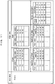
- the shape data are configured by data such as: vertex coordinate data indicating coordinates in the three-dimensional space of vertices constituting the three-dimensional shape of the imaged structural member; equation data of an edge which is formed by connecting two vertices with each other; edge data which correlate the edge with the two vertices; equation data of a plane surrounded by edges; and plane data which correlate the plane with the edges.
- the structural member constituting the machine tool is a bed, a spindle stock which is disposed on the bed, a main spindle which is rotatably supported on the spindle stock, a chuck which is attached to the main spindle, a saddle which is movably disposed on the bed, a tool rest which is disposed on the saddle, or the like.
- the structural member is a bed, a column which is disposed on the bed, a spindle head which is movably supported on the column, a main spindle which is rotatably supported on the spindle head, a table which is movably disposed on the bed, or the like.
- a structural member constituting a machine tool is imaged in three orthogonal directions, and three-dimensional model data of the structural member are automatically generated on the basis of two-dimensional image data which are obtained as a result of the imaging. Therefore, it is possible to efficiently generate correct three-dimensional model data.
- the apparatus for generating three-dimensional model data may be configured in the following manner.
- the apparatus further comprises model data storing means for previously storing three-dimensional model data of a whole of the machine tool in which three-dimensional model data of plural structural members constituting the machine tool are correlated with one another, and the model data generating means generates three-dimensional model data of a structural member which is imaged by the first, second, and third imaging means, on the basis of two-dimensional image data that are generated for the imaged structural member, calculates a coordinate position at which the imaged structural member is to be positioned on a three-dimensional model of the whole of the machine tool, and updates the three-dimensional model data of the whole of the machine tool on the basis of the calculated coordinate position data, the three-dimensional model data of the imaged structural member, and the three-dimensional model data of the whole of the machine tool which are stored in the model data storing means, thereby generating three-dimensional model data of the whole of the machine tool including the imaged structural member.
- three-dimensional model data of the whole machine tool in which three-dimensional model data of plural structural members constituting the machine tool are correlated with one another are previously stored into the model data storing means.
- the machine tool is an NC lathe
- three-dimensional model data of a bed and those of a tool rest and a spindle stock three-dimensional model data of the spindle stock and those of a main spindle
- three-dimensional model data of the main spindle and those of a chuck three-dimensional model data of the chuck and those of a workpiece, and the like are correlated with one another to constitute the three-dimensional model data of the whole machine tool.
- the three-dimensional model data of the whole machine tool are stored into the model data storing means.
- three-dimensional model data of the imaged structural member are then generated in the manner described above.
- a coordinate position at which a three-dimensional model of the imaged structural member is to be positioned in a three-dimensional model of the whole machine tool is then calculated based on relative positional relationships among the imaging sections of the imaging means and the machine tool.
- the three-dimensional model data of the whole machine tool stored in the model data storing means are then updated to generate three-dimensional model data of the whole of the machine tool in which the three-dimensional model data of the imaged structural member are placed.
- the three-dimensional model data of the imaged structural member do not exist in the three-dimensional model data of the whole machine tool stored in the model data storing means, three-dimensional model data of the whole machine tool to which the three-dimensional model data of the imaged structural member are added are generated.
- the three-dimensional model data of the other structural member are deleted, and three-dimensional model data of the whole machine tool to which the three-dimensional model data of the imaged structural member are added are then generated.
- correct three-dimensional model data of an imaged structural member can be efficiently generated, and three-dimensional model data of the whole machine tool including the imaged structural member can be updated and generated correctly (i.e., so as to coincide with the actual state of the machine tool) and efficiently.
- the three-dimensional model data of the structural member include information related to a movement axis and/or a rotation axis which is set with respect to the structural member.
- the imaged structural member is a tool rest
- three-dimensional model data of the tool rest are configured so as to include information that the tool rest is moved along the axis of the main spindle.
- three-dimensional model data of the chuck are configured so as to include information that the chuck is axially rotated. According to the configuration, the manner in which the imaged structural member is to be moved or rotated in the machine tool can be defined, and hence the three-dimensional model data are more suitable for an interference simulation.
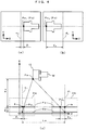
- FIG. 1 is a block diagram schematically showing the configuration of an apparatus for generating three-dimensional model data of an embodiment of the invention
- Fig. 2 is a side section view looking in the direction of the arrow A-A in Fig. 1 .
- the three-dimensional model data generating apparatus 1 of the embodiment comprises: an imaging device 20 which is mounted on a machine tool 10, and which images a structural member constituting the machine tool 10 to generate two-dimensional image data; an image data storing section 30 which stores the two-dimensional image data of the structural member that are generated by the imaging device 20; a model data generating section 31 which generates three-dimensional model data of the imaged structural member on the basis of the two-dimensional image data stored in the image data storing section 30; a model data storing section 32 which stores three-dimensional model data of the whole of the machine tool 10; and an input/output device 40 which is connected to the model data generating section 31 and the model data storing section 32.
- the machine tool 10 is an NC lathe, and configured by various structural members such as: a bed 11; a spindle stock (not shown) which is disposed on the bed 11; a main spindle 12 which is supported on the spindle stock (not shown) so as to be rotatable (in the C-axis direction) about the Z-axis (the axis which is parallel to the axis of the main spindle 12); a chuck 13 which is attached to the main spindle 12; and a tool rest 14 which is disposed on the bed 11 so as to be movable in the directions of the three orthogonal axes (the X-, Y-, and Z-axes).
- the chuck 13 is composed of a body unit 13a, and a plurality of gripping jaws 13b attached to the body unit 13a.
- the imaging device 20 is configured by: an X-axis imaging mechanism 21 comprising two CCD cameras 21a, 21b which are spaced apart from each other by a predetermined distance; a Y-axis imaging mechanism 22 comprising two CCD cameras 22a, 22b which are similarly spaced apart from each other by a predetermined distance; and a Z-axis imaging mechanism 23 comprising two CCD cameras 23a, 23b which are similarly spaced apart from each other by a predetermined distance.
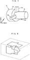
- the chuck 13 which grips a workpiece W shown in Fig. 7 is an object to be imaged.
- the X-axis imaging mechanism 21 is configured so that the CCD cameras 21a, 21b are arranged along the Z-axis to image the chuck 13 and the workpiece W in the direction along the X-axis
- the Y-axis imaging mechanism 22 is configured so that the CCD cameras 22a, 22b are arranged along the X-axis to image the chuck 13 and the workpiece W in the direction along the Y-axis
- the Z-axis imaging mechanism 23 is configured so that the CCD cameras 23a, 23b are arranged along the Y-axis to image the chuck 13 and the workpiece W in the direction along the Z-axis.
- the X-axis imaging mechanism 21, the Y-axis imaging mechanism 22, and the Z-axis imaging mechanism 23 are stored at their respective retracting positions, and, when the imaging process is to be performed, moved by driving devices 24, 25, 26 from the retracting positions to imaging positions, respectively.
- Each of the CCD cameras 21a, 21b, 22a, 22b, 23a, 23b comprises a plurality of photoelectric conversion elements which are two-dimensionally arranged in a multi-row, multi-column array, digitizes voltage signals which are output from the photoelectric conversion elements in accordance with the amount of received light, converts the digitized signals into gray level values, and outputs the values as two-dimensional gray-level image data which are arranged in the same manner as the arrangement of the photoelectric conversion elements.
- the image data storing section 30 stores the two-dimensional gray-level image data which are output from the CCD cameras 21a, 21b, 22a, 22b, 23a, 23b.
- Three-dimensional model data of the whole of the machine tool 10 which are adequately generated with using a three-dimensional CAD system or the like are previously stored via the input/output device 40 into the model data storing section 32.
- the three-dimensional model data of the whole of the machine tool 10 are configured so that three-dimensional model data of structural members constituting the machine tool 10 are correlated with one another.
- three-dimensional model data of the bed 11 and those of the tool rest 14 and the spindle stock (not shown), the three-dimensional model data of the spindle stock (not shown) and those of the main spindle 12, the three-dimensional model data of the main spindle 12 and those of the chuck 13, the three-dimensional model data of the chuck 13 and those of the workpiece W, and the like are correlated with one another to be generated as the three-dimensional model data of the whole machine tool 10.
- the generated three-dimensional model data are stored into the model data storing section 32.
- Each three-dimensional model data are configured so as to include at least shape data which define the three-dimensional shape of the structural member, and axis data related to a movement axis and/or a rotation axis which is set with respect to the structural member.
- the shape data are configured by: vertex coordinate data indicating coordinates in the three-dimensional space of vertices constituting the three-dimensional shape of the structural member; equation data of an edge which is formed by connecting two vertices with each other; edge data which correlate the edge with the two vertices; equation data of a plane surrounded by edges; plane data which correlate the plane with the edges; and other data.
- shape data shown in Fig. 11 are obtained.
- the axis data relate to the X-, Y-, and Z-axes
- the axis data relate to the C-axis.
- the model data generating section 31 generates three-dimensional model data which include at least shape data defining the three-dimensional shape of the chuck 13 and the workpiece W, on the basis of the two-dimensional gray-level image data stored in the image data storing section 30, calculates a coordinate position at which the chuck 13 and the workpiece W are to be positioned on a three-dimensional model of the whole of the machine tool 10, and updates the three-dimensional model data of the whole of the machine tool 10 on the basis of the calculated coordinate position data, the three-dimensional model data of the chuck 13 and the workpiece W, and the three-dimensional model data of the whole of the machine tool 10 which are stored in the model data storing section 32, thereby generating three-dimensional model data of the whole of the machine tool 10 including the chuck 13 and the workpiece W which are imaged.
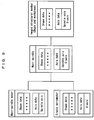
- the model data generating section 31 performs processes shown in Fig. 3 . It is assumed that the imaging device 20 images the chuck 13 gripping the workpiece W, and two-dimensional gray-level image data obtained by the imaging are stored in the image data storing section 30.
- the workpiece W and the chuck 13 are referred to as the imaged structural member.
- the model data generating section 31 first reads out the three-dimensional model data of the whole machine tool 10 stored in the model data storing section 32, from the model data storing section 32 (step S1), and reads out the two-dimensional gray-level image data of the imaged structural member stored in the image data storing section 30, from the image data storing section 30 (step S2).
- the read out two-dimensional image data are binarized by a predetermined threshold to extract images of the imaged structural member, and the extracted binarized images are scanned in the raster direction to extract contour lines of the binarized images (step S3).
- contour lines of the binarized images which are obtained by the CCD cameras 21a, 21b are shown in (a) and (b) of Fig. 4
- those of the binarized images which are obtained by the CCD cameras 22a, 22b are shown in (a) and (b) of Fig. 5
- those of the binarized images which are obtained by the CCD cameras 23a, 23b are shown in (a) and (b) of Fig. 6 .
- step S4 Based on the two contour lines which are extracted for each of imaging mechanisms of the X-axis imaging mechanism 21, the Y-axis imaging mechanism 22, and the Z-axis imaging mechanism 23, coordinate positions of real contour lines of the imaged structural member in a three-dimensional space are calculated for each of the imaging directions of the imaging mechanisms by the triangulation method (step S4).
- the calculated coordinate positions are relative coordinate positions with respect to the imaging mechanisms.
- the two CCD cameras 21a, 21b which obtain the images shown in (a) and (b) of Fig. 4 , and the entity of the imaged structural member are in the positional relationships in the X-Z plane shown in (c) of Fig. 4 .
- Fa denotes the center planes of lenses of the CCD cameras 21a, 21b
- Ga denotes the image surfaces.
- a denotes the lens center of the CCD camera 21a
- b denotes the lens center of the CCD camera 21b.
- Ra denotes the distance between the lens center plane Fa and the image surface Ga
- La denotes the distance between the lens centers a, b of the two CCD cameras 21a, 21b. These distances are previously accurately measured.
- c1 and d1 denote axes which are parallel to the X-axis, and which pass the centers a, b, respectively.
- a reference point in the entity of the imaged structural member is indicated by Pa, and lines respectively connecting points where the axes c1 and d1 intersect the image surface Ga, and the reference point Pa are set.
- the lines intersect the lens center plane Fa at points Pa1 and Pa2, respectively.
- light from the reference point Pa is received by the CCD cameras 21a, 21b intersects the respective lens center planes at the points Pa1 and Pa2 to be deflected by the respective lenses, and then further advances from the points Pa1 and Pa2 in parallel with the axes c1 and d1 to be imaged on the respective image surfaces.
- the points Pa1 and Pa2 correspond to portions which are in the contour line images of (a) and (b) of Fig. 4 , and which are denoted by the same reference numerals, respectively.
- the distance Xa in the X-axis direction between the CCD cameras 21a, 21b and the entity of the imaged structural member can be calculated by the triangulation method with using Expression (1) below.
- the distances Z1, Z2 can be easily calculated from the contour line images of (a) and (b) of Fig. 4 which are imaged by the CCD cameras 21a, 21b and then processed.
- c2 and d2 denote axes which are parallel to the Y-axis, and which pass the lens centers a, b, respectively.
- Xa Ra La ⁇ Z 1 ⁇ Z 2 / Z 1 + Z 2
- the distances between the CCD cameras 22a, 22b and the CCD cameras 23a, 23b, and the entity of the imaged structural member can be calculated in a similar manner as described above.
- (c) is a diagram showing the positional relationships in the X-Y plane among the CCD cameras 22a, 22b and the entity of the imaged structural member.
- Fb denotes the center planes of lenses of the CCD cameras 22a, 22b
- Gb denotes the image surfaces
- e denotes the lens center of the CCD camera 22a
- f denotes the lens center of the CCD camera 22b.
- Rb denotes the distance between the lens center plane Fb and the image surface Gb
- Lb denotes the distance between the lens centers e, f of the CCD cameras 22a, 22b
- g1 and h1 denote axes which are parallel to the Y-axis, and which pass the centers e, f, respectively.
- Pb denotes a reference point
- Pb1 and Pb2 denote points where lines respectively connecting intersections of the axes g1, h1 in the image surfaces Gb and the reference point Pb intersect the lens center plane Fb
- X1, X2 denote distances between the imaged points of the reference point Pb on the image surfaces Gb of the CCD cameras 22a, 22b, and the lens centers e, f.
- g2 and h2 denote axes which are parallel to the Z-axis, and which pass the centers e, f, respectively.
- (c) of Fig. 6 is a diagram showing the positional relationships in the Y-Z plane among the CCD cameras 23a, 23b and the entity of the imaged structural member.
- Fc denotes the center planes of lenses of the CCD cameras 23a, 23b
- Gc denotes the image surfaces
- j denotes the lens center of the CCD camera 23a
- k denotes the lens center of the CCD camera 23b.
- the reference symbol Rc denotes the distance between the lens center plane Fc and the image surface Gc
- Lc denotes the distance between the lens centers j, k of the CCD cameras 23a, 23b
- m1 and n1 denote axes which are parallel to the Z-axis, and which pass the centers j, k, respectively.
- Pc denotes a reference point
- Pc1 and Pc2 denote points where lines respectively connecting intersections of the axes m1, n1 in the image surfaces Gc and the reference point Pc intersect the lens center plane Fc
- Y1, Y2 denote distances between the imaged points of the reference point Pc on the image surfaces Gc of the CCD cameras 23a, 23b, and the lens centers j, k.
- m2 and n2 denote axes which are parallel to the X-axis, and which pass the centers j, k, respectively.
- the distance Yb between the CCD cameras 22a, 22b and the entity of the imaged structural member, and the distance Zc between the CCD cameras 23a, 23b and the entity of the imaged structural member can be calculated with using Expressions (2), (3) below.
- Yb Rb Lb ⁇ Z 1 ⁇ Z 2 / Z 1 + Z 2
- Zc Rc Lc ⁇ Z 1 ⁇ Z 2 / Z 1 + Z 2
- a three-dimensional shape of the imaged structural member in which the real contour lines are edges, respectively is estimated, and three-dimensional model data including at least shape data which define the three-dimensional shape are generated (step S 5).
- Fig. 8 is a conceptual diagram in which the real contour lines of the imaging directions are placed on the basis of the relative positional relationships among the CCD cameras 21a, 21b, 22a, 22b, 23a, 23b, and Fig. 7 shows the estimated three-dimensional shape of the imaged structural member.
- a coordinate position at which a three-dimensional model of the imaged structural member is to be positioned on a three-dimensional model of the machine tool 10 is calculated (step S6).
- the three-dimensional model data of the machine tool 10 are updated on the basis of the calculated coordinate position data on the three-dimensional model of the machine tool 10, the three-dimensional model data of the imaged structural member, and the three-dimensional model data of the machine tool 10 which are read out in step S1 (steps S7 to S12).
- step S7 it is checked whether, on the three-dimensional model of the machine tool 10 which is read out in step S1, a three-dimensional model of another structural member exists at a place where the three-dimensional model of the imaged structural member is to exist or not (step S7) . If a three-dimensional model of another structural member exists, the three-dimensional model data of the other structural member are deleted (step S8), and three-dimensional model data of the machine tool 10 to which the three-dimensional model data of the imaged structural member are added are generated (step S10) . Thereafter, the axis data are added to the three-dimensional model data of the imaged structural member (step S11), and these data are stored into the model data storing section 32 (step S12).
- the unique axial data of the imaged structural member are input by an interactive input through the input/output device 40.
- the connection relationships are automatically recognized, and the axis data related to the other structural member to be connected are automatically set as the axis data of the imaged structural member. As shown in Fig.
- the axis data of the imaged structural member consisting of the chuck to be connected with the main spindle and the workpiece are automatically set as the spindle axis and the C-axis which are the axis data of the main spindle.
- step S9 it is then judged whether the three-dimensional model data of the imaged structural member which are to be placed on the three-dimensional model of the machine tool 10 exist in the three-dimensional model data of the machine tool 10 that are read out in step S1 or not (step S9). If the three-dimensional model of the imaged structural member does not exist, the three-dimensional model data of the whole machine tool to which the three-dimensional model data of the imaged structural member are added are generated (steps S10, S11), and the generated three-dimensional model data are stored into the model data storing section 32 (step S12).
- the new structural member is imaged in the directions of the X-, Y-, and Z-axes (three orthogonal axis directions) by the X-axis imaging mechanism 21, the Y-axis imaging mechanism 22, and the Z-axis imaging mechanism 23 of the imaging device 20, and two-dimensional image data of the axis directions are generated.
- the generated two-dimensional image data are stored into the image data storing section 30.
- the two-dimensional image data stored in the image data storing section 30 are read out, the three-dimensional model data of the imaged structural member are generated on the basis of the read out two-dimensional image data, and, based on the generated three-dimensional model data of the imaged structural member, the three-dimensional model data of the machine tool 10 stored in the model data storing section 32 are updated.
- three-dimensional model data generating apparatus 1 three-dimensional model data are automatically generated from images taken by the imaging device 20. Even when a structural member constituting the machine tool 10 is changed, therefore, three-dimensional model data of the whole of the machine tool 10 after the change can be generated correctly and efficiently.
- the machine tool 10 includes various machine tools such as a machining center, and the imaged structural member includes various structural members constituting the machine tool 10, such as the tool rest 14 to which a tool T is attached, the main spindle holding a tool, and a table on which the workpiece W is placed.
- the CCD cameras 21a, 21b are arranged along the Z-axis
- the CCD cameras 22a, 22b are arranged along the X-axis
- the CCD cameras 23a, 23b are arranged along the Y-axis.
- the CCD cameras 21a, 21b may be arranged along the Y-axis
- the CCD cameras 22a, 22b may be arranged along the Z-axis
- the CCD cameras 23a, 23b may be arranged along the X-axis.
- two CCD cameras are disposed along each of the X-, Y-, and Z-axes, or a total of six CCD cameras are disposed.
- the invention is not restricted to this configuration.
- two CCD cameras may be disposed along one of the X-, Y-, and Z-axes, and the cameras are sequentially moved so as to be disposed along the other two axes, so that the structural member is imaged in the directions of the three axes of the X-, Y-, and Z-axes by the two CCD cameras.
- a single CCD camera may be disposed so as to be movable along the X-, Y-, and Z-axes, the structural member may be imaged from two places along each of the axes, and three-dimensional model data of the imaged structural member may be generated on the basis of the sets of two two-dimensional image data which are obtained for each of the axes.
Landscapes
- Engineering & Computer Science (AREA)
- Physics & Mathematics (AREA)
- General Physics & Mathematics (AREA)
- Theoretical Computer Science (AREA)
- Computer Vision & Pattern Recognition (AREA)
- Geometry (AREA)
- Computer Graphics (AREA)
- Software Systems (AREA)
- Numerical Control (AREA)
- Image Processing (AREA)
- Image Analysis (AREA)
- Length Measuring Devices By Optical Means (AREA)
Claims (3)
- Vorrichtung (1) zum Generieren dreidimensionaler Modelldaten eines Strukturelements, das eine Werkzeugmaschine (10) darstellt, in der ein Schlitten in Richtungen mindestens einer ersten und einer zweiten Achse beweglich ist, die senkrecht zueinander sind, umfassend:erste, zweite und dritte Bildgabemittel (21, 22, 23), wobei jedes der Bildgabemittel (21, 22, 23) zwei Bildgabesektionen (21a, 21b, 22a, 22b, 23a, 23b) umfasst, die um eine zuvor festgelegte Distanz voneinander beabstandet sind, wobei das Strukturelement durch die Bildgabesektionen (21a, 21b, 22a, 22b, 23a, 23b) abgebildet wird, um zweidimensionale Bilddaten zu generieren; undein Modelldatengenerierungsmittel (31) zum Generieren dreidimensionaler Modelldaten, die mindestens Formdaten enthalten, die eine dreidimensionale Form des Strukturelements definieren, auf der Basis von Sätzen aus zwei zweidimensionalen Bilddaten, die jeweils durch die ersten, zweiten und dritten Bildgabemittel (21, 22, 23) generiert werden,wobei die Vorrichtung (1) dadurch gekennzeichnet ist, dass: das erste Bildgabemittel (21) so ausgestaltet ist, dass die zwei Bildgabesektionen (21a, 21b) entlang der zweiten Achse oder einer dritten Achse angeordnet sind, die senkrecht zu der ersten und der zweiten Achse verläuft, und die Bildgabesektionen (21a, 21b) das Strukturelement in einer Richtung der ersten Achse abbilden,das zweite Bildgabemittel (22) so ausgestaltet ist, dass die zwei Bildgabesektionen (22a, 22b) entlang der ersten Achse oder der dritten Achse angeordnet sind und die Bildgabesektionen (22a, 22b) das Strukturelement in einer Richtung der zweiten Achse abbilden, unddas dritte Bildgabemittel (23) so ausgestaltet ist, dass die zwei Bildgabesektionen (23a, 23b) entlang der ersten Achse oder der zweiten Achse angeordnet sind und die Bildgabesektionen (23a, 23b) das Strukturelement in einer Richtung der dritten Achse abbilden, unddas Modelldatengenerierungsmittel (31) dafür ausgestaltet ist, Folgendes auszuführen:einen Prozess des Binarisierens, anhand einer zuvor festgelegten Schwelle, der zweidimensionalen Bilddaten, die jeweils durch die Bildgabemittel (21, 22, 23) generiert wurden, um binarisierte Bilder zu extrahieren, die dem Strukturelement entsprechen, und auf der Basis der extrahierten binarisierten Bilder Formlinien zu extrahieren, die Konturlinien des Strukturelements entsprechen,einen Prozess des Berechnens von Koordinatenpositionen realer Konturlinien des Strukturelements in einem dreidimensionalen Raum für jede der Bildgaberichtungen der Bildgabemittel (21, 22, 23) durch ein Triangulationsverfahren auf der Basis der zwei Formlinien, die jeweils für die Bildgabemittel (21, 22, 23) extrahiert werden, undeinen Prozessdes Schätzens einer dreidimensionalen Form des Strukturelements auf der Basis der berechneten Koordinatenpositionen der realen Konturlinien und der relativen Positionsbeziehungen zwischen den Bildgabesektionen der Bildgabemittel, unddes Generierens dreidimensionaler Modelldaten, die mindestens Formdaten enthalten, welche die dreidimensionale Form definieren,wobei die Formdaten Folgendes enthalten:Scheitelpunktkoordinatendaten, die in dem dreidimensionalen Raum Koordinaten von Scheitelpunkten enthalten, welche die dreidimensionale Form des Strukturelements bilden,Gleichungsdaten eines Randes, der durch Verbinden zweier Scheitelpunkte miteinander gebildet wird,Randdaten, den Rand mit den zwei Scheitelpunkten korrelieren,Gleichungsdaten einer Ebene, die von Rändern umgeben wird, undEbenendaten, welche die Ebene mit den Rändern korrelieren.
- Vorrichtung (1) zum Generieren dreidimensionaler Modelldaten nach Anspruch 1, wobei
die Vorrichtung (1) des Weiteren ein Modelldatenspeichermittel (32) zum Speichern dreidimensionaler Modelldaten der gesamten Werkzeugmaschine umfasst, wobei dreidimensionale Modelldaten mehrerer Strukturelemente, welche die Werkzeugmaschine darstellen, miteinander korreliert sind, und
das Modelldatengenerierungsmittel (31) dreidimensionale Modelldaten eines Strukturelements, das durch die ersten, zweiten und dritten Bildgabemittel (21, 22, 23) abgebildet wird, auf der Basis zweidimensionaler Bilddaten generiert, die für das abgebildete Strukturelement generiert wurden, eine Koordinatenposition berechnet, an der das abgebildete Strukturelement in einem dreidimensionalen Modell der gesamten Werkzeugmaschine positioniert werden soll, und die dreidimensionalen Modelldaten der gesamten Werkzeugmaschine auf der Basis der berechneten Koordinatenpositionsdaten, der dreidimensionalen Modelldaten des abgebildeten Strukturelements und der dreidimensionalen Modelldaten der gesamten Werkzeugmaschine, die in dem Modelldatenspeichermittel gespeichert sind, aktualisiert, wodurch dreidimensionale Modelldaten der gesamten Werkzeugmaschine, einschließlich des abgebildeten Strukturelements, generiert werden. - Vorrichtung (1) zum Generieren dreidimensionaler Modelldaten nach Anspruch 1 oder 2, wobei die dreidimensionalen Modelldaten des Strukturelements Informationen enthalten, die sich auf eine Bewegungsachse und/oder eine Rotationsachse beziehen, die mit Bezug auf das Strukturelement eingestellt wird.
Applications Claiming Priority (2)
| Application Number | Priority Date | Filing Date | Title |
|---|---|---|---|
| JP2002348669 | 2002-11-29 | ||
| JP2002348669A JP4083554B2 (ja) | 2002-11-29 | 2002-11-29 | 3次元モデルデータ生成装置 |
Publications (3)
| Publication Number | Publication Date |
|---|---|
| EP1424656A2 EP1424656A2 (de) | 2004-06-02 |
| EP1424656A3 EP1424656A3 (de) | 2006-02-08 |
| EP1424656B1 true EP1424656B1 (de) | 2019-04-10 |
Family
ID=32290507
Family Applications (1)
| Application Number | Title | Priority Date | Filing Date |
|---|---|---|---|
| EP03027310.6A Expired - Lifetime EP1424656B1 (de) | 2002-11-29 | 2003-11-26 | Verfahren und Vorrichtung zur Erzeugung von dreidimensionalen Modelldaten für Werkzeugmaschine |
Country Status (3)
| Country | Link |
|---|---|
| US (1) | US7403648B2 (de) |
| EP (1) | EP1424656B1 (de) |
| JP (1) | JP4083554B2 (de) |
Families Citing this family (28)
| Publication number | Priority date | Publication date | Assignee | Title |
|---|---|---|---|---|
| JP4505295B2 (ja) * | 2004-09-16 | 2010-07-21 | ヤマザキマザック株式会社 | Nc加工シミュレーション方法及びnc加工シミュレーション装置 |
| JP2006195971A (ja) * | 2004-12-16 | 2006-07-27 | Canon Inc | 三次元cadシステム |
| JP4658734B2 (ja) * | 2005-08-12 | 2011-03-23 | 中村留精密工業株式会社 | 旋盤における機械稼動部の衝突防止方法 |
| US8111904B2 (en) * | 2005-10-07 | 2012-02-07 | Cognex Technology And Investment Corp. | Methods and apparatus for practical 3D vision system |
| JP2007286976A (ja) * | 2006-04-18 | 2007-11-01 | Fanuc Ltd | ロボットシミュレーション装置 |
| JP5049975B2 (ja) * | 2006-09-01 | 2012-10-17 | 株式会社森精機製作所 | 3次元モデルデータ生成方法及び3次元モデルデータ生成装置 |
| JP4955451B2 (ja) * | 2007-05-16 | 2012-06-20 | ヤマザキマザック株式会社 | 複合旋盤装置の制御方法、複合旋盤装置、刃先位置登録装置、及び刃先位置検出装置 |
| JP4991504B2 (ja) * | 2007-12-06 | 2012-08-01 | 株式会社森精機製作所 | 干渉確認装置 |
| JP5014972B2 (ja) * | 2007-12-20 | 2012-08-29 | 株式会社森精機製作所 | 干渉確認装置 |
| JP5022924B2 (ja) * | 2008-01-23 | 2012-09-12 | 株式会社森精機製作所 | 干渉確認装置 |
| EP2096601B1 (de) * | 2008-02-29 | 2015-01-21 | FUJIFILM Corporation | Strahlungsbildaufnahmesystem, Strahlungsnachweisvorrichtung, Bildaufnahmebasis, Strahlungsbildaufnahmeverfahren und Programm |
| JP5399824B2 (ja) * | 2008-09-05 | 2014-01-29 | 株式会社森精機製作所 | 加工状況監視方法及び加工状況監視装置 |
| FR2951563A1 (fr) * | 2009-10-16 | 2011-04-22 | Logiparts Sa | Procede et installation d'analyse de parametres geometriques d'un objet |
| AU2011244225B2 (en) * | 2010-04-21 | 2015-04-23 | Accenture Global Services Limited | Method and system for analyzing geometric parameters of an object |
| US8958630B1 (en) * | 2011-10-24 | 2015-02-17 | Google Inc. | System and method for generating a classifier for semantically segmenting an image |
| KR101975840B1 (ko) * | 2011-12-23 | 2019-05-10 | 두산공작기계 주식회사 | 이기종 수치제어장치를 위한 공작기계 정보 관리 장치 및 그 방법 |
| EP2672461A1 (de) * | 2012-06-05 | 2013-12-11 | a.tron3d GmbH | Verfahren zum Fortsetzen von Aufnahmen zum Erfassen von dreidimensionalen Geometrien von Objekten |
| JP6434476B2 (ja) | 2016-12-06 | 2018-12-05 | ファナック株式会社 | 拡張現実シミュレーション装置及び拡張現実シミュレーションプログラム |
| JP6426772B2 (ja) * | 2017-02-07 | 2018-11-21 | ファナック株式会社 | 座標情報変換装置及び座標情報変換プログラム |
| JP6412185B2 (ja) | 2017-03-02 | 2018-10-24 | ファナック株式会社 | 工作機械システム |
| JP6585665B2 (ja) | 2017-06-29 | 2019-10-02 | ファナック株式会社 | 仮想オブジェクト表示システム |
| JP6659641B2 (ja) | 2017-09-13 | 2020-03-04 | ファナック株式会社 | 3次元モデル作成装置 |
| JP6781201B2 (ja) | 2018-06-05 | 2020-11-04 | ファナック株式会社 | 仮想オブジェクト表示システム |
| JP7063764B2 (ja) | 2018-08-08 | 2022-05-09 | ファナック株式会社 | 3次元モデル作成装置 |
| TWI669484B (zh) * | 2018-10-12 | 2019-08-21 | 財團法人工業技術研究院 | 加工程式與對應之切削刀具之匹配辨識方法與系統 |
| AU2020323613A1 (en) | 2019-08-01 | 2022-02-17 | Prefect Technologies, Inc | System and method for the remote execution of one or more arbitrarily defined workflows |
| CN113455864B (zh) * | 2021-07-27 | 2022-08-12 | 深圳市简如法工程咨询有限公司 | 一种自动快速三维支模装置及支模方法 |
| US12472531B2 (en) | 2021-12-03 | 2025-11-18 | Stratasys, Inc. | Method and system for classifying additive manufactured objects |
Citations (5)
| Publication number | Priority date | Publication date | Assignee | Title |
|---|---|---|---|---|
| WO2000021034A1 (en) * | 1998-10-06 | 2000-04-13 | Easyscan Műszaki Fejlesztő Kereskedelmi És Szolgál Tató Kft. | Method and apparatus for the scanning of spatial objects and to create a three dimensional computer model |
| US6128405A (en) * | 1996-08-30 | 2000-10-03 | Minolta Co., Ltd. | System for processing three-dimensional shape data |
| US6363169B1 (en) * | 1997-07-23 | 2002-03-26 | Sanyo Electric Co., Ltd. | Apparatus and method of three-dimensional modeling |
| EP1207496A1 (de) * | 2000-04-27 | 2002-05-22 | Tohoku Techno Arch Co., Ltd. | Vorrichtung zur bildung von dreidimensionalen modelen |
| US20020159628A1 (en) * | 2001-04-26 | 2002-10-31 | Mitsubishi Electric Research Laboratories, Inc | Image-based 3D digitizer |
Family Cites Families (12)
| Publication number | Priority date | Publication date | Assignee | Title |
|---|---|---|---|---|
| EP0116561A1 (de) | 1982-05-18 | 1984-08-29 | THOMAS, Gareth David | Verfahren und vorrichtung zur ausführung von bearbeitungen dreidimensionaler objekte |
| GB8304032D0 (en) | 1982-05-18 | 1983-03-16 | Thomas G D | Reproduction of three-dimensional surfaces |
| US4654872A (en) * | 1983-07-25 | 1987-03-31 | Omron Tateisi Electronics Co. | System for recognizing three-dimensional objects |
| JPH06161533A (ja) | 1992-11-25 | 1994-06-07 | Sanyo Electric Co Ltd | 3次元測定装置の制御方式 |
| JP2810320B2 (ja) * | 1994-04-18 | 1998-10-15 | 住友ゴム工業株式会社 | 球体の回転量測定装置及び測定方法 |
| FR2756042B1 (fr) * | 1996-11-15 | 1999-01-29 | Aerospatiale | Systeme de mesure des caracteristiques d'un objet |
| US6173070B1 (en) * | 1997-12-30 | 2001-01-09 | Cognex Corporation | Machine vision method using search models to find features in three dimensional images |
| US6072898A (en) * | 1998-01-16 | 2000-06-06 | Beaty; Elwin M. | Method and apparatus for three dimensional inspection of electronic components |
| JP2001154715A (ja) | 1999-11-25 | 2001-06-08 | Toshiba Corp | 3次元cad装置、3次元cam装置及び記憶媒体 |
| KR100356016B1 (ko) * | 1999-12-21 | 2002-10-18 | 한국전자통신연구원 | 영상인식에 의한 소포우편물 부피계측시스템 및부피계측방법 |
| JP3673749B2 (ja) * | 2001-11-12 | 2005-07-20 | ファナック株式会社 | シミュレーション装置 |
| JP2003150219A (ja) | 2001-11-12 | 2003-05-23 | Fanuc Ltd | 作業機械のシミュレーション装置 |
-
2002
- 2002-11-29 JP JP2002348669A patent/JP4083554B2/ja not_active Expired - Fee Related
-
2003
- 2003-11-25 US US10/720,110 patent/US7403648B2/en not_active Expired - Fee Related
- 2003-11-26 EP EP03027310.6A patent/EP1424656B1/de not_active Expired - Lifetime
Patent Citations (5)
| Publication number | Priority date | Publication date | Assignee | Title |
|---|---|---|---|---|
| US6128405A (en) * | 1996-08-30 | 2000-10-03 | Minolta Co., Ltd. | System for processing three-dimensional shape data |
| US6363169B1 (en) * | 1997-07-23 | 2002-03-26 | Sanyo Electric Co., Ltd. | Apparatus and method of three-dimensional modeling |
| WO2000021034A1 (en) * | 1998-10-06 | 2000-04-13 | Easyscan Műszaki Fejlesztő Kereskedelmi És Szolgál Tató Kft. | Method and apparatus for the scanning of spatial objects and to create a three dimensional computer model |
| EP1207496A1 (de) * | 2000-04-27 | 2002-05-22 | Tohoku Techno Arch Co., Ltd. | Vorrichtung zur bildung von dreidimensionalen modelen |
| US20020159628A1 (en) * | 2001-04-26 | 2002-10-31 | Mitsubishi Electric Research Laboratories, Inc | Image-based 3D digitizer |
Also Published As
| Publication number | Publication date |
|---|---|
| EP1424656A2 (de) | 2004-06-02 |
| EP1424656A3 (de) | 2006-02-08 |
| US7403648B2 (en) | 2008-07-22 |
| US20040107018A1 (en) | 2004-06-03 |
| JP4083554B2 (ja) | 2008-04-30 |
| JP2004185123A (ja) | 2004-07-02 |
Similar Documents
| Publication | Publication Date | Title |
|---|---|---|
| EP1424656B1 (de) | Verfahren und Vorrichtung zur Erzeugung von dreidimensionalen Modelldaten für Werkzeugmaschine | |
| JP5049975B2 (ja) | 3次元モデルデータ生成方法及び3次元モデルデータ生成装置 | |
| JP6222898B2 (ja) | 3次元計測装置及びロボット装置 | |
| JP5469216B2 (ja) | バラ積みされた物品をロボットで取出す装置 | |
| JP4195096B2 (ja) | 3次元表面形状再構築のための装置 | |
| EP2045772B1 (de) | Vorrichtung zur Aufnahme von Objekten | |
| JP5606786B2 (ja) | キャリブレーション方法及びキャリブレーション装置 | |
| US20040172164A1 (en) | Method and apparatus for single image 3D vision guided robotics | |
| CN111644935A (zh) | 一种机器人三维扫描测量装置及工作方法 | |
| EP1286309A2 (de) | Prozess zur einer automatischen CAD-geführten Sensorplanung | |
| JPH0852638A (ja) | 干渉チェック方法および加工プログラムチェック方法および加工適否チェック方法 | |
| JP4085671B2 (ja) | データ処理方法、データ処理プログラムおよび記録媒体 | |
| JP2024096756A (ja) | ロボット搭載移動装置、及びその制御方法 | |
| Seçil et al. | 3-d visualization system for geometric parts using a laser profile sensor and an industrial robot | |
| JPH07276206A (ja) | ワーク表面自動加工装置 | |
| CN112123028B (zh) | 一种大铸件粗打磨系统 | |
| Tian et al. | Quick 3D modeling of machining environment by means of on-machine stereo vision with digital decomposition | |
| CN121199755B (zh) | 一种数控机床刀具加工变比齿轮的路径规划方法及系统 | |
| Rossi et al. | 3D object reconstruction using a robot arm | |
| Hendrix et al. | Vision Survey System, a tool for providing 3D product definition data of large constructions | |
| JP6894590B2 (ja) | 基準点特定装置、加工プログラム生成システム、基準点特定方法 | |
| Siebrecht et al. | Methodology for the automated digitization and probing of workpieces in a machining center by combining optical and tactile measurements | |
| TW202333920A (zh) | 取得工件位置之裝置、機器人之控制裝置、機器人系統及方法 | |
| della Vallea et al. | A Robotic Application Developed at DiME to Scan and Reproduces Objects | |
| Kaneko et al. | Development of Tool Shape Estimation Method Integrating Multidirectional Optical Measurement |
Legal Events
| Date | Code | Title | Description |
|---|---|---|---|
| PUAI | Public reference made under article 153(3) epc to a published international application that has entered the european phase |
Free format text: ORIGINAL CODE: 0009012 |
|
| AK | Designated contracting states |
Kind code of ref document: A2 Designated state(s): AT BE BG CH CY CZ DE DK EE ES FI FR GB GR HU IE IT LI LU MC NL PT RO SE SI SK TR |
|
| AX | Request for extension of the european patent |
Extension state: AL LT LV MK |
|
| PUAL | Search report despatched |
Free format text: ORIGINAL CODE: 0009013 |
|
| AK | Designated contracting states |
Kind code of ref document: A3 Designated state(s): AT BE BG CH CY CZ DE DK EE ES FI FR GB GR HU IE IT LI LU MC NL PT RO SE SI SK TR |
|
| AX | Request for extension of the european patent |
Extension state: AL LT LV MK |
|
| RIC1 | Information provided on ipc code assigned before grant |
Ipc: G06T 7/00 20060101ALI20051221BHEP Ipc: G06T 17/20 20060101AFI20040227BHEP Ipc: G05B 19/00 20060101ALI20051221BHEP |
|
| 17P | Request for examination filed |
Effective date: 20060302 |
|
| AKX | Designation fees paid |
Designated state(s): DE FR GB IT |
|
| RAP1 | Party data changed (applicant data changed or rights of an application transferred) |
Owner name: INTELLIGENT MANUFACTURING SYSTEMS INTERNATIONAL Owner name: DMG MORI SEIKI CO., LTD. |
|
| 17Q | First examination report despatched |
Effective date: 20140717 |
|
| STAA | Information on the status of an ep patent application or granted ep patent |
Free format text: STATUS: EXAMINATION IS IN PROGRESS |
|
| GRAP | Despatch of communication of intention to grant a patent |
Free format text: ORIGINAL CODE: EPIDOSNIGR1 |
|
| STAA | Information on the status of an ep patent application or granted ep patent |
Free format text: STATUS: GRANT OF PATENT IS INTENDED |
|
| INTG | Intention to grant announced |
Effective date: 20180621 |
|
| GRAS | Grant fee paid |
Free format text: ORIGINAL CODE: EPIDOSNIGR3 |
|
| RIC1 | Information provided on ipc code assigned before grant |
Ipc: G06T 17/20 20060101AFI20040227BHEP Ipc: G06T 7/00 20170101ALI20051221BHEP Ipc: G05B 19/00 20060101ALI20051221BHEP |
|
| GRAA | (expected) grant |
Free format text: ORIGINAL CODE: 0009210 |
|
| STAA | Information on the status of an ep patent application or granted ep patent |
Free format text: STATUS: THE PATENT HAS BEEN GRANTED |
|
| AK | Designated contracting states |
Kind code of ref document: B1 Designated state(s): DE FR GB IT |
|
| REG | Reference to a national code |
Ref country code: GB Ref legal event code: FG4D |
|
| REG | Reference to a national code |
Ref country code: DE Ref legal event code: R096 Ref document number: 60351921 Country of ref document: DE |
|
| REG | Reference to a national code |
Ref country code: DE Ref legal event code: R097 Ref document number: 60351921 Country of ref document: DE |
|
| PGFP | Annual fee paid to national office [announced via postgrant information from national office to epo] |
Ref country code: DE Payment date: 20191121 Year of fee payment: 17 |
|
| PLBE | No opposition filed within time limit |
Free format text: ORIGINAL CODE: 0009261 |
|
| STAA | Information on the status of an ep patent application or granted ep patent |
Free format text: STATUS: NO OPPOSITION FILED WITHIN TIME LIMIT |
|
| PG25 | Lapsed in a contracting state [announced via postgrant information from national office to epo] |
Ref country code: IT Free format text: LAPSE BECAUSE OF FAILURE TO SUBMIT A TRANSLATION OF THE DESCRIPTION OR TO PAY THE FEE WITHIN THE PRESCRIBED TIME-LIMIT Effective date: 20190410 |
|
| 26N | No opposition filed |
Effective date: 20200113 |
|
| GBPC | Gb: european patent ceased through non-payment of renewal fee |
Effective date: 20191126 |
|
| PG25 | Lapsed in a contracting state [announced via postgrant information from national office to epo] |
Ref country code: GB Free format text: LAPSE BECAUSE OF NON-PAYMENT OF DUE FEES Effective date: 20191126 Ref country code: FR Free format text: LAPSE BECAUSE OF NON-PAYMENT OF DUE FEES Effective date: 20191130 |
|
| REG | Reference to a national code |
Ref country code: DE Ref legal event code: R119 Ref document number: 60351921 Country of ref document: DE |
|
| PG25 | Lapsed in a contracting state [announced via postgrant information from national office to epo] |
Ref country code: DE Free format text: LAPSE BECAUSE OF NON-PAYMENT OF DUE FEES Effective date: 20210601 |