EP1424191A2 - Machine pour la production d'articles à partir de flans plats - Google Patents
Machine pour la production d'articles à partir de flans plats Download PDFInfo
- Publication number
- EP1424191A2 EP1424191A2 EP03026901A EP03026901A EP1424191A2 EP 1424191 A2 EP1424191 A2 EP 1424191A2 EP 03026901 A EP03026901 A EP 03026901A EP 03026901 A EP03026901 A EP 03026901A EP 1424191 A2 EP1424191 A2 EP 1424191A2
- Authority
- EP
- European Patent Office
- Prior art keywords
- machine
- frame
- blanks
- folding
- rollers
- Prior art date
- Legal status (The legal status is an assumption and is not a legal conclusion. Google has not performed a legal analysis and makes no representation as to the accuracy of the status listed.)
- Granted
Links
- 239000000463 material Substances 0.000 title claims abstract description 10
- 230000001360 synchronised effect Effects 0.000 claims description 5
- 230000000284 resting effect Effects 0.000 claims 1
- 230000000712 assembly Effects 0.000 description 7
- 238000000429 assembly Methods 0.000 description 7
- 239000000853 adhesive Substances 0.000 description 6
- 230000001070 adhesive effect Effects 0.000 description 6
- 230000003287 optical effect Effects 0.000 description 6
- 239000011324 bead Substances 0.000 description 2
- 230000006835 compression Effects 0.000 description 1
- 238000007906 compression Methods 0.000 description 1
- 238000010276 construction Methods 0.000 description 1
- 238000001514 detection method Methods 0.000 description 1
- 238000004519 manufacturing process Methods 0.000 description 1
- 239000002184 metal Substances 0.000 description 1
- 230000000717 retained effect Effects 0.000 description 1
Images

Classifications
-
- B—PERFORMING OPERATIONS; TRANSPORTING
- B65—CONVEYING; PACKING; STORING; HANDLING THIN OR FILAMENTARY MATERIAL
- B65H—HANDLING THIN OR FILAMENTARY MATERIAL, e.g. SHEETS, WEBS, CABLES
- B65H5/00—Feeding articles separated from piles; Feeding articles to machines
- B65H5/06—Feeding articles separated from piles; Feeding articles to machines by rollers or balls, e.g. between rollers
- B65H5/062—Feeding articles separated from piles; Feeding articles to machines by rollers or balls, e.g. between rollers between rollers or balls
-
- B—PERFORMING OPERATIONS; TRANSPORTING
- B65—CONVEYING; PACKING; STORING; HANDLING THIN OR FILAMENTARY MATERIAL
- B65H—HANDLING THIN OR FILAMENTARY MATERIAL, e.g. SHEETS, WEBS, CABLES
- B65H45/00—Folding thin material
- B65H45/12—Folding articles or webs with application of pressure to define or form crease lines
- B65H45/30—Folding in combination with creasing, smoothing or application of adhesive
-
- F—MECHANICAL ENGINEERING; LIGHTING; HEATING; WEAPONS; BLASTING
- F16—ENGINEERING ELEMENTS AND UNITS; GENERAL MEASURES FOR PRODUCING AND MAINTAINING EFFECTIVE FUNCTIONING OF MACHINES OR INSTALLATIONS; THERMAL INSULATION IN GENERAL
- F16B—DEVICES FOR FASTENING OR SECURING CONSTRUCTIONAL ELEMENTS OR MACHINE PARTS TOGETHER, e.g. NAILS, BOLTS, CIRCLIPS, CLAMPS, CLIPS OR WEDGES; JOINTS OR JOINTING
- F16B2/00—Friction-grip releasable fastenings
- F16B2/02—Clamps, i.e. with gripping action effected by positive means other than the inherent resistance to deformation of the material of the fastening
- F16B2/06—Clamps, i.e. with gripping action effected by positive means other than the inherent resistance to deformation of the material of the fastening external, i.e. with contracting action
- F16B2/12—Clamps, i.e. with gripping action effected by positive means other than the inherent resistance to deformation of the material of the fastening external, i.e. with contracting action using sliding jaws
-
- B—PERFORMING OPERATIONS; TRANSPORTING
- B31—MAKING ARTICLES OF PAPER, CARDBOARD OR MATERIAL WORKED IN A MANNER ANALOGOUS TO PAPER; WORKING PAPER, CARDBOARD OR MATERIAL WORKED IN A MANNER ANALOGOUS TO PAPER
- B31B—MAKING CONTAINERS OF PAPER, CARDBOARD OR MATERIAL WORKED IN A MANNER ANALOGOUS TO PAPER
- B31B50/00—Making rigid or semi-rigid containers, e.g. boxes or cartons
- B31B50/02—Feeding or positioning sheets, blanks or webs
- B31B50/04—Feeding sheets or blanks
- B31B50/042—Feeding sheets or blanks using rolls, belts or chains
-
- B—PERFORMING OPERATIONS; TRANSPORTING
- B31—MAKING ARTICLES OF PAPER, CARDBOARD OR MATERIAL WORKED IN A MANNER ANALOGOUS TO PAPER; WORKING PAPER, CARDBOARD OR MATERIAL WORKED IN A MANNER ANALOGOUS TO PAPER
- B31B—MAKING CONTAINERS OF PAPER, CARDBOARD OR MATERIAL WORKED IN A MANNER ANALOGOUS TO PAPER
- B31B70/00—Making flexible containers, e.g. envelopes or bags
- B31B70/26—Folding sheets, blanks or webs
-
- B—PERFORMING OPERATIONS; TRANSPORTING
- B31—MAKING ARTICLES OF PAPER, CARDBOARD OR MATERIAL WORKED IN A MANNER ANALOGOUS TO PAPER; WORKING PAPER, CARDBOARD OR MATERIAL WORKED IN A MANNER ANALOGOUS TO PAPER
- B31B—MAKING CONTAINERS OF PAPER, CARDBOARD OR MATERIAL WORKED IN A MANNER ANALOGOUS TO PAPER
- B31B70/00—Making flexible containers, e.g. envelopes or bags
- B31B70/60—Uniting opposed surfaces or edges; Taping
- B31B70/62—Uniting opposed surfaces or edges; Taping by adhesives
-
- B—PERFORMING OPERATIONS; TRANSPORTING
- B42—BOOKBINDING; ALBUMS; FILES; SPECIAL PRINTED MATTER
- B42C—BOOKBINDING
- B42C7/00—Manufacturing bookbinding cases or covers of books or loose-leaf binders
- B42C7/008—Conveying means between operation stations
-
- B—PERFORMING OPERATIONS; TRANSPORTING
- B65—CONVEYING; PACKING; STORING; HANDLING THIN OR FILAMENTARY MATERIAL
- B65H—HANDLING THIN OR FILAMENTARY MATERIAL, e.g. SHEETS, WEBS, CABLES
- B65H2402/00—Constructional details of the handling apparatus
- B65H2402/50—Machine elements
- B65H2402/51—Joints, e.g. riveted or magnetic joints
-
- B—PERFORMING OPERATIONS; TRANSPORTING
- B65—CONVEYING; PACKING; STORING; HANDLING THIN OR FILAMENTARY MATERIAL
- B65H—HANDLING THIN OR FILAMENTARY MATERIAL, e.g. SHEETS, WEBS, CABLES
- B65H2404/00—Parts for transporting or guiding the handled material
- B65H2404/10—Rollers
- B65H2404/15—Roller assembly, particular roller arrangement
- B65H2404/154—Rollers conveyor
-
- B—PERFORMING OPERATIONS; TRANSPORTING
- B65—CONVEYING; PACKING; STORING; HANDLING THIN OR FILAMENTARY MATERIAL
- B65H—HANDLING THIN OR FILAMENTARY MATERIAL, e.g. SHEETS, WEBS, CABLES
- B65H2511/00—Dimensions; Position; Numbers; Identification; Occurrences
- B65H2511/10—Size; Dimensions
-
- B—PERFORMING OPERATIONS; TRANSPORTING
- B65—CONVEYING; PACKING; STORING; HANDLING THIN OR FILAMENTARY MATERIAL
- B65H—HANDLING THIN OR FILAMENTARY MATERIAL, e.g. SHEETS, WEBS, CABLES
- B65H2511/00—Dimensions; Position; Numbers; Identification; Occurrences
- B65H2511/20—Location in space
Definitions
- the present invention relates to a forming machine for producing articles of sheet material from flat, preferably die-cut blanks.
- the present invention relates to a folding and gumming machine for producing flexible or paperback covers, presentation folders, cases, boxes, etc., to which the following description refers purely by way of example.
- a flat blank is fed along a forming path through a number of forming stations, in each of which the blank is subjected to a specific operation, e.g. folding, gumming, pressing, etc.
- conveyor belt assemblies are used, which, depending on the application, comprise a single conveyor belt looped about a powered roller and a return roller, or a number of separate powered conveyor belts smaller across than the single conveyor belt, arranged side by side, and an adjustable distance apart to adapt the supporting area to the size of the blanks.
- the blanks are secured in position on the delivery branch/es of the conveyor belt/s using pressure devices, featuring rollers or single or side by side wheels, which are fitted to respective structures or frames separate from the conveyor, and are connectable directly by the machine operator to a fixed structure, depending on the article being produced. Again depending on the article being produced, the operator positions and locks helical or plate-type folding members on the conveyor belts.
- the position of the blanks along the feed path is determined by means of optical detectors.
- Using a single conveyor belt prevents the optical devices from being installed underneath the delivery branch of the conveyor, makes it difficult for the blank to be detected over the delivery branch, by preventing the use of through-beam optical detectors, and prevents the blank from being worked on from underneath the delivery branch of the belt.
- a forming machine for producing articles of sheet material from flat blanks; the machine comprising powered conveying means for feeding an orderly succession of flat blanks along a forming path, and pressure means for holding said blanks on the conveying means; and being characterized in that said conveying means comprise a roller conveyor comprising two lateral shoulders, a number of intermediate rollers, each connected to the shoulders to rotate about a respective axis, and synchronous drive means for rotating each of said rollers about its axis; said pressure means being fitted to supporting means comprising a supporting frame, and locating and retaining means associated with said shoulders to locate and lock the supporting frame along the forming path in a number of fixed relative reference positions with respect to the shoulders.
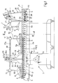
- Number 1 in Figures 1 and 2 indicates as a whole a forming machine for producing articles 2 of sheet material - in the example shown, flexible or presentation folders - from flat blanks 2a ( Figure 2).
- machine 1 comprises a base 3 supporting a powered roller conveyor 4, in turn comprising two parallel, longitudinal lateral shoulders 5 facing each other and separated transversely, and a number of intermediate rollers 6 extending perpendicularly to shoulders 5.
- Rollers 6 are the same shape and size, are connected to shoulders 5 to rotate about respective fixed parallel axes 6a equally spaced with a spacing P, and are connected to a common synchronous powered mechanical drive 7.
- drive 7 is a chain drive, in which an electric motor 8 powers an endless chain 9 comprising a top drive branch 10 meshing with a number of identical toothed wheels 11, each fitted to one end of a relative roller 6, and a bottom return branch 12, along which is fitted a known adjustable chain tensioning device 13 not described in detail ( Figure 1).
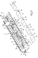
- Roller conveyor 4 defines a support for blanks 2a, and cooperates with a number of known preloaded-idle-wheel pressure devices 15 located over conveyor 4, to feed, in use, an orderly succession of blanks 2a along a straight forming path K ( Figure 2) and through a number of work stations.
- Pressure devices 15 comprise a number of wheels rotating idly about respective parallel axes 15a separated by a spacing P1 equal to spacing P, and each located precisely at a respective roller 6.
- Devices 15 are connected to respective support assemblies 18 ( Figures 1 and 3), each of which comprises a respective gantry-type frame 19, in turn comprising two uprights 20, preferably made of bent, welded sheet metal, and a cross member 21 separate from uprights 20 and connected releasably to the ends of uprights 20.
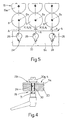
- Each upright 20 extends upwards from a relative lateral shoulder 5, and is connected to shoulder 5 by a respective locating and retaining assembly 22 forming part of assembly 18 and comprising a respective row of locating seats 24, which are formed in a plate portion 5a of shoulder 5, with a spacing P2 equal to spacing P of rollers 6, and are each located exactly beneath a respective roller 6.
- each locating seat 24 is defined by a vertical slot symmetrical with respect to a relative vertical plane A containing axis 6a of relative roller 6 and axis 15a of the corresponding idle wheels, if present.
- each slot forms the bottom portion of a relative keyhole opening 26 ( Figure 5), and each locating assembly 22 also comprises two screw-nut screw ties 28 ( Figures 1-4), each of which comprises a respective locating and lock screw 29 ( Figure 4), the threaded shank 30 of which extends parallel to axes 6a through a hole formed at the bottom end of relative upright 20, and through a relative slot 24, into which it is inserted by inserting its head 30a through opening 26 ( Figure 5) in portion 5a.
- the portion of shank 30 projecting outwards of upright 20 is fitted with a nut 31, which cooperates with head 30a to grip together upright 20 and the portion of shoulder 5 defining slot 24.
- each upright 20 terminates at the top with a respective fork
- cross member 21 has two opposite end portions 32 and 33 housed between the arms of the respective forks; portion 32 is hinged to the fork by a horizontal hinge pin 34'; and portion 33 is retained contacting relative upright 20 by a known toggle forcing device 34 on the outside of upright 20.
- the retaining action of device 34 is opposed by a compression spring 34a gripped between a bottom stop surface of upright 20 and cross member 21, and which distances cross member 21 from roller conveyor 4 when device 34 is released.
- Cross member 21 is hung with relative pressure devices 15, the position of which along path K and with respect to shoulders 5 is adjustable, as a function of the shape and size of blanks 2a, by respective supporting and adjusting assemblies 35 forming part of assembly 18.
- Each assembly 35 comprises a first and second guide and slide assembly, indicated 36 and 37, for adjusting said position along two perpendicular axes 36a and 37a parallel to axes 6a of rollers 6 and the travelling direction K of blanks 2a respectively.
- assembly 36 comprises a straight guide defined by cross member 21; and a slide defined by a substantially C-shaped, side-fit jaw 38 ( Figure 6). More specifically, jaw 38 comprises a bottom portion 39, a lateral portion 40, and a top connecting portion 41, which together define a guide seat 42 engaged in sliding manner by cross member 21.
- Jaw 38 can be locked at any point along cross member 21 by means of a screw clamping device 43 comprising a plate 44 connected to lateral portion 40 to translate, under the control of a screw-nut screw assembly 45, between a lowered rest position allowing jaw 38 to move freely along cross member 21 and/or release of jaw 38 from cross member 21, and a raised lock position in which it grips and locks jaw 38 and cross member 21 together.
- a screw clamping device 43 comprising a plate 44 connected to lateral portion 40 to translate, under the control of a screw-nut screw assembly 45, between a lowered rest position allowing jaw 38 to move freely along cross member 21 and/or release of jaw 38 from cross member 21, and a raised lock position in which it grips and locks jaw 38 and cross member 21 together.
- Bottom portion 39 is hollow, and defines a through seat 47 fitted through with a rod or beam 48 parallel to travelling direction K and forming part of second assembly 37 together with seat 47.
- Rod 48 can be positioned and locked inside seat 47 by means of a number of screws 49.
- rod 48 is fitted with pressure devices 15, the vertical arms 50 of which are connected to rod 48 by respective jaws 51, which are shown schematically, are functionally similar to jaws 38, and mainly differ by relative portions 40 being in the form of portions 39 of jaws 38, i.e. defining a vertical slideway for arm 50.
- Jaws 51 therefore provide for adjusting the height of pressure devices 15 with respect to roller conveyor 4, and define, together with respective rods 48, further guide and slide assemblies for adjusting the position of pressure devices 15 parallel to axis 37a.
- machine 1 also comprises a lateral deflecting and folding coil 52, and a front fold-over device 53 (Figure 2), which, like pressure devices 15, are fitted to respective assemblies 35 connected to cross members 21 of relative frames 19.
- fold-over device 53 comprises a nozzle 55 located beneath roller conveyor 4 and extending in the gap defined by two consecutive rollers 6 to emit a stream of compressed air; and a cam 56 located over conveyor 4 and downstream from nozzle 55 in the travelling direction of blanks 2a.
- cross members 21 are also fitted with a gumming device 57 ( Figure 2) located over roller conveyor 4, at a gap defined by two consecutive rollers 6, to deposit a bead of adhesive material onto a portion of the blank, and a number of conveniently through-beam-type optical devices 58 for detecting the presence or absence of a blank along forming path K.
- gumming device 57 optical devices 58 are also located over roller conveyor 4, each at a gap defined by two consecutive rollers 6.
- a blank 2a is fed to the input of roller conveyor 4, and, by the rotation of rollers 6 and the pressure exerted by a first pressure device 15, is fed along path K through a folding station 60 equipped with coil 52, which, as shown in Figure 2, is designed to fold a projecting lateral tab 61 inwards of blank 2a and onto an intermediate portion of the blank to produce a semifinished article 2b; semifinished article 2b is then fed through a gumming station 62 where gumming device 57 deposits a bead B of adhesive material onto the folded tab 61.
- the gummed semifinished article is fed to a further folding station 63 where a free end of a front tab 64 is first raised gradually off roller conveyor 4 by the stream of air from nozzle 55, and is then turned backwards and over so that part of front tab 64 is superimposed on lateral tab 61, to which it is gummed by the adhesive material to form a pocket 64.
- the above devices are positioned accurately, regardless of the size and shape of the input blanks.
- the gumming and detecting devices in particular, these can each be located, as stated, at one of the gaps in the roller conveyor, so that any ill-dispensed adhesive material does not come into contact with the roller conveyor, and detection of the blanks/semifinished articles can be performed using any type of optical device either over or under the roller conveyor.
- the pressure or folding or gumming devices can be withdrawn rapidly from the roller conveyor in the event of crumpling, incorrect folding or deformation of the blanks.
Landscapes
- Engineering & Computer Science (AREA)
- Mechanical Engineering (AREA)
- General Engineering & Computer Science (AREA)
- Making Paper Articles (AREA)
- Folding Of Thin Sheet-Like Materials, Special Discharging Devices, And Others (AREA)
- Perforating, Stamping-Out Or Severing By Means Other Than Cutting (AREA)
Applications Claiming Priority (2)
| Application Number | Priority Date | Filing Date | Title |
|---|---|---|---|
| IT001038A ITTO20021038A1 (it) | 2002-11-29 | 2002-11-29 | Macchina di formatura per la realizzazione di articoli |
| ITTO20021038 | 2002-11-29 |
Publications (3)
| Publication Number | Publication Date |
|---|---|
| EP1424191A2 true EP1424191A2 (fr) | 2004-06-02 |
| EP1424191A3 EP1424191A3 (fr) | 2005-02-02 |
| EP1424191B1 EP1424191B1 (fr) | 2009-04-15 |
Family
ID=32259987
Family Applications (1)
| Application Number | Title | Priority Date | Filing Date |
|---|---|---|---|
| EP03026901A Expired - Fee Related EP1424191B1 (fr) | 2002-11-29 | 2003-11-24 | Machine pour la production d'articles à partir de flans plats |
Country Status (5)
| Country | Link |
|---|---|
| US (1) | US6981939B2 (fr) |
| EP (1) | EP1424191B1 (fr) |
| AT (1) | ATE428554T1 (fr) |
| DE (2) | DE20321704U1 (fr) |
| IT (1) | ITTO20021038A1 (fr) |
Cited By (7)
| Publication number | Priority date | Publication date | Assignee | Title |
|---|---|---|---|---|
| US7544159B2 (en) * | 2006-11-24 | 2009-06-09 | Giorgio Petratto | Machine for producing articles of sheet material |
| DE102009023110A1 (de) | 2008-05-28 | 2009-12-03 | Giorgio Petratto | Vorrichtung zum Ausrichten von Rohlingen in einer Falt- und Klebemaschine und Falt- und Klebemaschine, die mit dieser Vorrichtung versehen ist |
| US8061242B2 (en) | 2007-08-01 | 2011-11-22 | Kama Gmbh | Tool carrier device and apparatus for processing flat blanks |
| DE102011101740A1 (de) | 2010-05-14 | 2012-03-29 | Giorgio Petratto | Ergänzende modulare Einheit für eine Fertigungsstraße für Vorformen aus Blattmaterial und Linie, die diese Einheit beinhaltet |
| DE102013006528A1 (de) | 2012-04-30 | 2013-10-31 | Giorgio Petratto | Werkzeugträgergruppe in einer Maschine zur Bearbeitung von Halbwaren aus blattförmigem Material |
| DE102014012211A1 (de) * | 2014-08-16 | 2016-02-18 | Eisenmann Ag | Fördervorrichtung für Transportstrukturen |
| CN111497319A (zh) * | 2020-06-04 | 2020-08-07 | 合肥柱石科技有限公司 | 导料整料机构 |
Families Citing this family (6)
| Publication number | Priority date | Publication date | Assignee | Title |
|---|---|---|---|---|
| US9358727B2 (en) * | 2012-11-06 | 2016-06-07 | Miller Weldmaster Corporation | Dual roll fabric welding machine and method of operation |
| CN105516809B (zh) * | 2015-12-14 | 2019-02-26 | 深圳Tcl数字技术有限公司 | 电视机的开机控制电路及方法 |
| CN109532119B (zh) * | 2018-11-28 | 2020-10-13 | 孟庆平 | 一种瓦楞纸板的生产输送装置 |
| CN112551232A (zh) * | 2020-12-02 | 2021-03-26 | 安徽力幕新材料科技有限公司 | 一种用于铝板带箔的防护设备 |
| US20220373129A1 (en) * | 2021-05-20 | 2022-11-24 | John Powers, III | Arcuate mounting bracket and fabrication system |
| CN117125399B (zh) * | 2023-10-27 | 2024-01-30 | 荣智工企智能技术(昆山)有限公司 | 一种动力电池全包胶极片滚筒输送机 |
Citations (3)
| Publication number | Priority date | Publication date | Assignee | Title |
|---|---|---|---|---|
| US5019026A (en) * | 1989-02-09 | 1991-05-28 | Bobst Sa | Device for aligning box blanks within a machine used for processing them |
| US5413327A (en) * | 1993-02-09 | 1995-05-09 | Bobst Sa | Device for aligning box blanks for a machine processing box blanks |
| CH689300A5 (fr) * | 1993-09-30 | 1999-02-15 | Bobst Sa | Machine plieuse-colleuse incorporant un transporteur à rouleaux. |
Family Cites Families (8)
| Publication number | Priority date | Publication date | Assignee | Title |
|---|---|---|---|---|
| CH528374A (de) * | 1971-03-10 | 1972-09-30 | Mueller Hans Grapha Masch | Verfahren und Vorrichtung zur Herstellung von aus einer Vielzahl von Papierbogen zusammengefügten Büchern, Broschüren oder Heften |
| US4419088A (en) * | 1981-06-19 | 1983-12-06 | Nemec David G | Gate folding apparatus |
| GB8729442D0 (en) * | 1987-12-17 | 1988-02-03 | Chambon Ltd | Carton blank die-cutting machine assembly |
| US4979933A (en) * | 1988-04-27 | 1990-12-25 | Kraft, Inc. | Reclosable bag |
| DE59300080D1 (de) * | 1993-02-18 | 1995-03-23 | Jensen Ag Burgdorf | Falteinrichtung zum automatischen Falten von Wäschestücken. |
| DE19814917C2 (de) * | 1998-04-03 | 2000-09-21 | Texpa Maschinenbau Gmbh & Co K | Anlage zum Falten eines Textilbahnabschnitts |
| IT1316185B1 (it) * | 2000-01-24 | 2003-04-03 | Engico Srl | Macchina automatica per la fenditura e la cordonatura di cartone infogli e simili |
| US6612974B2 (en) * | 2001-02-01 | 2003-09-02 | Hallmark Cards Incorporated | Adjustable folding station for cards |
-
2002
- 2002-11-29 IT IT001038A patent/ITTO20021038A1/it unknown
-
2003
- 2003-11-24 AT AT03026901T patent/ATE428554T1/de not_active IP Right Cessation
- 2003-11-24 EP EP03026901A patent/EP1424191B1/fr not_active Expired - Fee Related
- 2003-11-24 DE DE20321704U patent/DE20321704U1/de not_active Expired - Lifetime
- 2003-11-24 DE DE60327149T patent/DE60327149D1/de not_active Expired - Lifetime
- 2003-11-28 US US10/724,573 patent/US6981939B2/en not_active Expired - Lifetime
Patent Citations (3)
| Publication number | Priority date | Publication date | Assignee | Title |
|---|---|---|---|---|
| US5019026A (en) * | 1989-02-09 | 1991-05-28 | Bobst Sa | Device for aligning box blanks within a machine used for processing them |
| US5413327A (en) * | 1993-02-09 | 1995-05-09 | Bobst Sa | Device for aligning box blanks for a machine processing box blanks |
| CH689300A5 (fr) * | 1993-09-30 | 1999-02-15 | Bobst Sa | Machine plieuse-colleuse incorporant un transporteur à rouleaux. |
Cited By (9)
| Publication number | Priority date | Publication date | Assignee | Title |
|---|---|---|---|---|
| US7544159B2 (en) * | 2006-11-24 | 2009-06-09 | Giorgio Petratto | Machine for producing articles of sheet material |
| US8061242B2 (en) | 2007-08-01 | 2011-11-22 | Kama Gmbh | Tool carrier device and apparatus for processing flat blanks |
| DE102009023110A1 (de) | 2008-05-28 | 2009-12-03 | Giorgio Petratto | Vorrichtung zum Ausrichten von Rohlingen in einer Falt- und Klebemaschine und Falt- und Klebemaschine, die mit dieser Vorrichtung versehen ist |
| DE102011101740A1 (de) | 2010-05-14 | 2012-03-29 | Giorgio Petratto | Ergänzende modulare Einheit für eine Fertigungsstraße für Vorformen aus Blattmaterial und Linie, die diese Einheit beinhaltet |
| DE102013006528A1 (de) | 2012-04-30 | 2013-10-31 | Giorgio Petratto | Werkzeugträgergruppe in einer Maschine zur Bearbeitung von Halbwaren aus blattförmigem Material |
| DE102014012211A1 (de) * | 2014-08-16 | 2016-02-18 | Eisenmann Ag | Fördervorrichtung für Transportstrukturen |
| US10124958B2 (en) | 2014-08-16 | 2018-11-13 | Eisenmann Se | Conveyor device for transporation structures |
| CN111497319A (zh) * | 2020-06-04 | 2020-08-07 | 合肥柱石科技有限公司 | 导料整料机构 |
| CN111497319B (zh) * | 2020-06-04 | 2021-02-23 | 合肥柱石科技有限公司 | 导料整料机构 |
Also Published As
| Publication number | Publication date |
|---|---|
| EP1424191A3 (fr) | 2005-02-02 |
| US6981939B2 (en) | 2006-01-03 |
| DE20321704U1 (de) | 2009-02-19 |
| US20040162204A1 (en) | 2004-08-19 |
| ITTO20021038A1 (it) | 2004-05-30 |
| DE60327149D1 (de) | 2009-05-28 |
| ATE428554T1 (de) | 2009-05-15 |
| EP1424191B1 (fr) | 2009-04-15 |
Similar Documents
| Publication | Publication Date | Title |
|---|---|---|
| EP1424191B1 (fr) | Machine pour la production d'articles à partir de flans plats | |
| US4704100A (en) | Bag making apparatus and method | |
| US7828708B2 (en) | Case erector and sealer apparatus | |
| KR100648870B1 (ko) | 판형 작업물을 처리하는 기계에서의 판형 작업물의 정렬 장치 | |
| EP1818262B1 (fr) | Unité de positionnement d'une feuille de film pour couvrir le dessus de groupes de produits | |
| DE4042178C2 (de) | Vorrichtung zum Anbringen von Etiketten oder dergleichen an Packungen | |
| DD213890A5 (de) | Verfahren und vorrichtung zum herstellen von sammelpackungen | |
| AU2007262577B2 (en) | Device for machining continuously successively transported, flat objects or an almost endless web of material | |
| JP2000505749A (ja) | 4側面テーパー付きカートン用ローラーホールドダウン装置 | |
| JP2010535142A (ja) | コンベアベルト上を移動する実質的平行六面体対象物の群を形成する方法及び装置 | |
| WO1992007712A1 (fr) | Dispositif de pliage de cartons | |
| AU2008281716B2 (en) | Tool carrier device and device for machining flat sections | |
| DE60224714T2 (de) | Verfahren zum Verpacken von Zigaretten in Weichpackungen | |
| DE19955993A1 (de) | Maschine zum Einhängen von Buchblocks in Buchdecken | |
| EP1707488A1 (fr) | Table d'entrée reglable pour machine d'emballage | |
| JPH034468B2 (fr) | ||
| US10351355B2 (en) | Auto changeover infeed assembly | |
| WO2009121542A1 (fr) | Équipement et procédé de fabrication de sacs à partir de tronçons de tube souple | |
| CN210911380U (zh) | 一种自动压纹机 | |
| EP1818263A1 (fr) | Procédé pour emballer des produits et son usage dans une machine correspondante | |
| US3330715A (en) | Apparatus for applying adhesive patterns to flat cardboard elements | |
| EP1456085B1 (fr) | Appareil et procede pour le traitement d'un paquet du type pochette a tabac | |
| EP1002727A2 (fr) | Dispositif d'assemblage et de transport, en particulier pour système d'emballage | |
| US20120035033A1 (en) | Device for supplying sheets | |
| FI89553C (fi) | Foerfarande och anordning foer matning av dragkedsraecka med sprundflikar |
Legal Events
| Date | Code | Title | Description |
|---|---|---|---|
| PUAI | Public reference made under article 153(3) epc to a published international application that has entered the european phase |
Free format text: ORIGINAL CODE: 0009012 |
|
| AK | Designated contracting states |
Kind code of ref document: A2 Designated state(s): AT BE BG CH CY CZ DE DK EE ES FI FR GB GR HU IE IT LI LU MC NL PT RO SE SI SK TR |
|
| AX | Request for extension of the european patent |
Extension state: AL LT LV MK |
|
| PUAL | Search report despatched |
Free format text: ORIGINAL CODE: 0009013 |
|
| AK | Designated contracting states |
Kind code of ref document: A3 Designated state(s): AT BE BG CH CY CZ DE DK EE ES FI FR GB GR HU IE IT LI LU MC NL PT RO SE SI SK TR |
|
| AX | Request for extension of the european patent |
Extension state: AL LT LV MK |
|
| RIC1 | Information provided on ipc code assigned before grant |
Ipc: 7B 31B 19/26 B Ipc: 7B 31B 1/04 A Ipc: 7B 31B 19/60 B Ipc: 7B 65H 29/12 B Ipc: 7B 65G 39/18 B |
|
| 17P | Request for examination filed |
Effective date: 20050727 |
|
| AKX | Designation fees paid |
Designated state(s): AT BE BG CH CY CZ DE DK EE ES FI FR GB GR HU IE IT LI LU MC NL PT RO SE SI SK TR |
|
| GRAP | Despatch of communication of intention to grant a patent |
Free format text: ORIGINAL CODE: EPIDOSNIGR1 |
|
| TPAC | Observations filed by third parties |
Free format text: ORIGINAL CODE: EPIDOSNTIPA |
|
| GRAS | Grant fee paid |
Free format text: ORIGINAL CODE: EPIDOSNIGR3 |
|
| GRAA | (expected) grant |
Free format text: ORIGINAL CODE: 0009210 |
|
| AK | Designated contracting states |
Kind code of ref document: B1 Designated state(s): AT BE BG CH CY CZ DE DK EE ES FI FR GB GR HU IE IT LI LU MC NL PT RO SE SI SK TR |
|
| REG | Reference to a national code |
Ref country code: CH Ref legal event code: EP Ref country code: GB Ref legal event code: FG4D |
|
| REG | Reference to a national code |
Ref country code: IE Ref legal event code: FG4D |
|
| REG | Reference to a national code |
Ref country code: CH Ref legal event code: NV Representative=s name: KELLER & PARTNER PATENTANWAELTE AG |
|
| REF | Corresponds to: |
Ref document number: 60327149 Country of ref document: DE Date of ref document: 20090528 Kind code of ref document: P |
|
| NLV1 | Nl: lapsed or annulled due to failure to fulfill the requirements of art. 29p and 29m of the patents act | ||
| PG25 | Lapsed in a contracting state [announced via postgrant information from national office to epo] |
Ref country code: ES Free format text: LAPSE BECAUSE OF FAILURE TO SUBMIT A TRANSLATION OF THE DESCRIPTION OR TO PAY THE FEE WITHIN THE PRESCRIBED TIME-LIMIT Effective date: 20090726 Ref country code: AT Free format text: LAPSE BECAUSE OF FAILURE TO SUBMIT A TRANSLATION OF THE DESCRIPTION OR TO PAY THE FEE WITHIN THE PRESCRIBED TIME-LIMIT Effective date: 20090415 Ref country code: PT Free format text: LAPSE BECAUSE OF FAILURE TO SUBMIT A TRANSLATION OF THE DESCRIPTION OR TO PAY THE FEE WITHIN THE PRESCRIBED TIME-LIMIT Effective date: 20090915 Ref country code: FI Free format text: LAPSE BECAUSE OF FAILURE TO SUBMIT A TRANSLATION OF THE DESCRIPTION OR TO PAY THE FEE WITHIN THE PRESCRIBED TIME-LIMIT Effective date: 20090415 |
|
| PG25 | Lapsed in a contracting state [announced via postgrant information from national office to epo] |
Ref country code: NL Free format text: LAPSE BECAUSE OF FAILURE TO SUBMIT A TRANSLATION OF THE DESCRIPTION OR TO PAY THE FEE WITHIN THE PRESCRIBED TIME-LIMIT Effective date: 20090415 Ref country code: SE Free format text: LAPSE BECAUSE OF FAILURE TO SUBMIT A TRANSLATION OF THE DESCRIPTION OR TO PAY THE FEE WITHIN THE PRESCRIBED TIME-LIMIT Effective date: 20090715 Ref country code: SI Free format text: LAPSE BECAUSE OF FAILURE TO SUBMIT A TRANSLATION OF THE DESCRIPTION OR TO PAY THE FEE WITHIN THE PRESCRIBED TIME-LIMIT Effective date: 20090415 |
|
| PLBI | Opposition filed |
Free format text: ORIGINAL CODE: 0009260 |
|
| PG25 | Lapsed in a contracting state [announced via postgrant information from national office to epo] |
Ref country code: EE Free format text: LAPSE BECAUSE OF FAILURE TO SUBMIT A TRANSLATION OF THE DESCRIPTION OR TO PAY THE FEE WITHIN THE PRESCRIBED TIME-LIMIT Effective date: 20090415 Ref country code: DK Free format text: LAPSE BECAUSE OF FAILURE TO SUBMIT A TRANSLATION OF THE DESCRIPTION OR TO PAY THE FEE WITHIN THE PRESCRIBED TIME-LIMIT Effective date: 20090415 Ref country code: CZ Free format text: LAPSE BECAUSE OF FAILURE TO SUBMIT A TRANSLATION OF THE DESCRIPTION OR TO PAY THE FEE WITHIN THE PRESCRIBED TIME-LIMIT Effective date: 20090415 Ref country code: RO Free format text: LAPSE BECAUSE OF FAILURE TO SUBMIT A TRANSLATION OF THE DESCRIPTION OR TO PAY THE FEE WITHIN THE PRESCRIBED TIME-LIMIT Effective date: 20090415 |
|
| PLAX | Notice of opposition and request to file observation + time limit sent |
Free format text: ORIGINAL CODE: EPIDOSNOBS2 |
|
| 26 | Opposition filed |
Opponent name: KAMA GMBH Effective date: 20100115 |
|
| PG25 | Lapsed in a contracting state [announced via postgrant information from national office to epo] |
Ref country code: SK Free format text: LAPSE BECAUSE OF FAILURE TO SUBMIT A TRANSLATION OF THE DESCRIPTION OR TO PAY THE FEE WITHIN THE PRESCRIBED TIME-LIMIT Effective date: 20090415 Ref country code: BE Free format text: LAPSE BECAUSE OF FAILURE TO SUBMIT A TRANSLATION OF THE DESCRIPTION OR TO PAY THE FEE WITHIN THE PRESCRIBED TIME-LIMIT Effective date: 20090415 |
|
| PG25 | Lapsed in a contracting state [announced via postgrant information from national office to epo] |
Ref country code: BG Free format text: LAPSE BECAUSE OF FAILURE TO SUBMIT A TRANSLATION OF THE DESCRIPTION OR TO PAY THE FEE WITHIN THE PRESCRIBED TIME-LIMIT Effective date: 20090715 |
|
| PLBB | Reply of patent proprietor to notice(s) of opposition received |
Free format text: ORIGINAL CODE: EPIDOSNOBS3 |
|
| PG25 | Lapsed in a contracting state [announced via postgrant information from national office to epo] |
Ref country code: MC Free format text: LAPSE BECAUSE OF NON-PAYMENT OF DUE FEES Effective date: 20091130 |
|
| REG | Reference to a national code |
Ref country code: IE Ref legal event code: MM4A |
|
| PG25 | Lapsed in a contracting state [announced via postgrant information from national office to epo] |
Ref country code: IE Free format text: LAPSE BECAUSE OF NON-PAYMENT OF DUE FEES Effective date: 20091124 Ref country code: GR Free format text: LAPSE BECAUSE OF FAILURE TO SUBMIT A TRANSLATION OF THE DESCRIPTION OR TO PAY THE FEE WITHIN THE PRESCRIBED TIME-LIMIT Effective date: 20090716 |
|
| PG25 | Lapsed in a contracting state [announced via postgrant information from national office to epo] |
Ref country code: IT Free format text: LAPSE BECAUSE OF FAILURE TO SUBMIT A TRANSLATION OF THE DESCRIPTION OR TO PAY THE FEE WITHIN THE PRESCRIBED TIME-LIMIT Effective date: 20090415 |
|
| PG25 | Lapsed in a contracting state [announced via postgrant information from national office to epo] |
Ref country code: LU Free format text: LAPSE BECAUSE OF NON-PAYMENT OF DUE FEES Effective date: 20091124 |
|
| PG25 | Lapsed in a contracting state [announced via postgrant information from national office to epo] |
Ref country code: HU Free format text: LAPSE BECAUSE OF FAILURE TO SUBMIT A TRANSLATION OF THE DESCRIPTION OR TO PAY THE FEE WITHIN THE PRESCRIBED TIME-LIMIT Effective date: 20091016 |
|
| PG25 | Lapsed in a contracting state [announced via postgrant information from national office to epo] |
Ref country code: TR Free format text: LAPSE BECAUSE OF FAILURE TO SUBMIT A TRANSLATION OF THE DESCRIPTION OR TO PAY THE FEE WITHIN THE PRESCRIBED TIME-LIMIT Effective date: 20090415 |
|
| PG25 | Lapsed in a contracting state [announced via postgrant information from national office to epo] |
Ref country code: CY Free format text: LAPSE BECAUSE OF FAILURE TO SUBMIT A TRANSLATION OF THE DESCRIPTION OR TO PAY THE FEE WITHIN THE PRESCRIBED TIME-LIMIT Effective date: 20090415 |
|
| PLCK | Communication despatched that opposition was rejected |
Free format text: ORIGINAL CODE: EPIDOSNREJ1 |
|
| PLBN | Opposition rejected |
Free format text: ORIGINAL CODE: 0009273 |
|
| STAA | Information on the status of an ep patent application or granted ep patent |
Free format text: STATUS: OPPOSITION REJECTED |
|
| 27O | Opposition rejected |
Effective date: 20130219 |
|
| REG | Reference to a national code |
Ref country code: DE Ref legal event code: R100 Ref document number: 60327149 Country of ref document: DE Effective date: 20130219 |
|
| REG | Reference to a national code |
Ref country code: CH Ref legal event code: PCAR Free format text: NEW ADDRESS: EIGERSTRASSE 2 POSTFACH, 3000 BERN 14 (CH) |
|
| REG | Reference to a national code |
Ref country code: FR Ref legal event code: PLFP Year of fee payment: 13 |
|
| REG | Reference to a national code |
Ref country code: FR Ref legal event code: PLFP Year of fee payment: 14 |
|
| REG | Reference to a national code |
Ref country code: DE Ref legal event code: R079 Ref document number: 60327149 Country of ref document: DE Free format text: PREVIOUS MAIN CLASS: B31B0001040000 Ipc: B31B0050040000 |
|
| REG | Reference to a national code |
Ref country code: FR Ref legal event code: PLFP Year of fee payment: 15 |
|
| REG | Reference to a national code |
Ref country code: CH Ref legal event code: PFA Owner name: PETRATTO S.R.L., IT Free format text: FORMER OWNER: PETRATTO S.R.L., IT |
|
| PGFP | Annual fee paid to national office [announced via postgrant information from national office to epo] |
Ref country code: CH Payment date: 20201123 Year of fee payment: 18 Ref country code: GB Payment date: 20201126 Year of fee payment: 18 Ref country code: FR Payment date: 20201126 Year of fee payment: 18 Ref country code: DE Payment date: 20201130 Year of fee payment: 18 |
|
| REG | Reference to a national code |
Ref country code: DE Ref legal event code: R119 Ref document number: 60327149 Country of ref document: DE |
|
| REG | Reference to a national code |
Ref country code: CH Ref legal event code: PL |
|
| GBPC | Gb: european patent ceased through non-payment of renewal fee |
Effective date: 20211124 |
|
| PG25 | Lapsed in a contracting state [announced via postgrant information from national office to epo] |
Ref country code: GB Free format text: LAPSE BECAUSE OF NON-PAYMENT OF DUE FEES Effective date: 20211124 Ref country code: DE Free format text: LAPSE BECAUSE OF NON-PAYMENT OF DUE FEES Effective date: 20220601 |
|
| PG25 | Lapsed in a contracting state [announced via postgrant information from national office to epo] |
Ref country code: FR Free format text: LAPSE BECAUSE OF NON-PAYMENT OF DUE FEES Effective date: 20211130 |
|
| PG25 | Lapsed in a contracting state [announced via postgrant information from national office to epo] |
Ref country code: LI Free format text: LAPSE BECAUSE OF NON-PAYMENT OF DUE FEES Effective date: 20220630 Ref country code: CH Free format text: LAPSE BECAUSE OF NON-PAYMENT OF DUE FEES Effective date: 20220630 |