EP1424107A1 - Gleitbrett, insbesondere Ski - Google Patents
Gleitbrett, insbesondere Ski Download PDFInfo
- Publication number
- EP1424107A1 EP1424107A1 EP02026618A EP02026618A EP1424107A1 EP 1424107 A1 EP1424107 A1 EP 1424107A1 EP 02026618 A EP02026618 A EP 02026618A EP 02026618 A EP02026618 A EP 02026618A EP 1424107 A1 EP1424107 A1 EP 1424107A1
- Authority
- EP
- European Patent Office
- Prior art keywords
- fastening elements
- interface
- ski
- board according
- guide element
- Prior art date
- Legal status (The legal status is an assumption and is not a legal conclusion. Google has not performed a legal analysis and makes no representation as to the accuracy of the status listed.)
- Granted
Links
Images


Classifications
-
- A—HUMAN NECESSITIES
- A63—SPORTS; GAMES; AMUSEMENTS
- A63C—SKATES; SKIS; ROLLER SKATES; DESIGN OR LAYOUT OF COURTS, RINKS OR THE LIKE
- A63C5/00—Skis or snowboards
- A63C5/12—Making thereof; Selection of particular materials
- A63C5/128—A part for the binding being integrated within the board structure, e.g. plate, rail, insert
-
- A—HUMAN NECESSITIES
- A63—SPORTS; GAMES; AMUSEMENTS
- A63C—SKATES; SKIS; ROLLER SKATES; DESIGN OR LAYOUT OF COURTS, RINKS OR THE LIKE
- A63C9/00—Ski bindings
- A63C9/003—Non-swivel sole plate fixed on the ski
Definitions
- the invention relates to a gliding board, in particular a ski, with at least one the gliding board connected via fasteners interface or Guide element for arranging binding elements and the like on the Top of the sliding board, which has a single or multi-layer top and Lower flange, a tread, steel edges if necessary and a foamed one Core.
- FIG. 1 Another version of a sliding board with a guide system is from the EP-A-1 161 072 known.
- This management system consists of a pair of Profile rails that have at least one molded dowel or dowel section connected to the gliding board body by a dowel connection or anchoring become.
- the profile rails are attached to the already finished sliding board and thus only replaces the otherwise usual screw fastening. In the field of attached profile rails, ski deflection is not possible or strong with special needs.
- the object is achieved in that the interface or guide element by means of at least one of the fastening elements on Sliding board is arranged in a fixed position, and by means of the further Fasteners in the longitudinal direction of the sliding board a limited Allowing mobility, is fixed, and that the interface or Fastening element that fixes the position when it is foamed of the core and curing of the foam has been incorporated into it.
- An inventive arrangement of the interface or guide elements on The sliding board thus allows the sliding board to bend while driving.
- the interface or guide element is preferably on one of its in End regions lying in the longitudinal direction are arranged in a fixed position, this End region is preferably that which is closer to the center of the gliding board.
- the Positional arrangement of the interface or guide elements is therefore carried out especially in the area of the ski center between the ski ends and supports the desired mobility of the ski or gliding board.
- the one that positions the interface or guide element in a fixed position Fastening element can either be firmly connected to the guide element or be made in one piece with this. Both variants allow a simple one and expedient embodiment of the invention.
- the other fastening elements hold the interface or guide element at least in the vertical direction and in the transverse direction.
- the limited mobility of the interface or guide elements in The longitudinal direction of the gliding board can be easily achieved by mounting points or receiving openings in the interface or guide elements for the other fasteners are provided, ensure that these Receiving points in the longitudinal direction of the sliding board have exemptions or provide.
- the interface or Guide element together with the other fasteners opposite the sliding board is arranged to be movable in the longitudinal direction. This too Execution can be easily made, for example by adding the others Fastening elements on the inside of the sliding board are limited to receiving parts can be arranged movably, which when foaming the core and Curing of the foam have been incorporated.
- This embodiment is particularly advantageous if the inside of the Sliding board located receiving parts for the fastener components a scaffold or the like integrated into the gliding board interior.
- the receiving parts are in particular designed such that they Have receiving openings in which the further fastening elements, each after execution at least in the vertical direction and in the transverse direction, are held.
- the interface or guide element is common is movable with the other fastening elements relative to the gliding board the other fasteners are both within the Opening openings of the receiving parts as well as limited to the top chord arranged movably. This can be done easily by providing Clearances in the openings in the top flange and in the receiving openings of the Receiving parts are ensured.
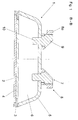
- FIG. 1 and FIG. 2 show sections through a ski 1, which has an outsole 2, Steel edges 3, a lower flange 4 and an upper flange 5.
- the core 6 of the Skis is foamed and anchored fasteners 7, 7a for profiled, here as Guiding elements 8 running and running parallel to one another.
- the guide elements 8 provided in pairs in this embodiment are used to slide on functional elements of a ski binding, for example a front or a rear binding part or a base plate, Support plate or the like.
- the fasteners 7, 7a are during the Foaming process and the subsequent curing of the foam material of the core 6 integrated and fixed in the ski 1. The one shown in FIGS.
- Embodiment are three fastening elements for each guide element 8, two of which are provided with the reference number 7 and one with the reference number 7a is provided.
- the two profiled guide elements 8 are like 2 and 3 show in particular, for example with guide strips 8a provided so that the binding member, the support plate or the like slidably can be pushed and slidably arranged.
- the holding the guide elements 8 on the top of the ski 1 Fastening elements 7, 7a each consist of an anchoring part 10 and a connecting part 19.
- the anchoring part 10 comprises that part of the Fastening element 7, 7a, which runs inside the ski 1, the Connecting part 9 that part which remains above the top of the ski.
- the Anchoring part 10 has an elongated, in the illustrated embodiment in Ski longitudinal direction extending foot part 10a, which on its long sides is each provided with a notch 10b.
- the foot part 10a can be on different types, the provision of which is essential Adhesive surface to the foam material of the core 6 areas or Areas, such as the notches 10b, and the ability to Fastening element 7, 7a through an opening 5a punched out in the upper chord 5 to be able to carry out and position the manufacture of the ski 1. It can also are provided on the anchoring part 10 after its positioning in To attach the upper flange 5 elements that increase the adhesive surface, for example, clip on or screw on.
- Each fastening element 7, 7a sits with an opening 5a on the edge circumferential paragraph 9a on the top of the top chord 5. Another, to the Paragraph 9a, followed by a level 9b, permits Supporting the respective fastening element 7, 7a on a support surface 11a a receiving opening 11 in the guide element 8.
- the top view shown in FIG. 3 on the pair of guide elements 8 leaves the for this embodiment selected shape of the receiving openings 11, substantially rectangular and in Longitudinal ski direction, recognize.
- this is the one provided with the reference number 7a Fastening element in the longitudinal direction of the ski at the end region of the guide element 8 provided and fixedly and immovably connected to the guide element 8, by the receiving opening 11 and the connecting part 9 fit one another are coordinated.
- receiving openings 11 are in the longitudinal direction of the ski 1 Gaps are provided as exemptions 12, 13.
- the exemptions 12 are each between the connecting part 9 and the Receiving opening 11 in the longitudinal direction of the ski and above the support surface 11a bounding walls, the exemptions 13 between paragraphs 9a and delimiting the receiving opening 11 in the longitudinal direction of the ski, below the Support surface 11a extending wall areas. So allow the other two Fastening elements 7 a limited mobility of the guide elements 8 in Ski longitudinal direction.
- the two guide elements 8 are connected to the Ski 1 in the making of the same. To do this, all fasteners 7, 7a positioned in the receiving openings 11 of the guide elements 8, the Guide elements 8 positioned on the upper belt material and the Fastening elements 7, 7a when foaming the core 6 in the core material anchored. It can also be provided that the guide element 8 firmly and immovably connected fastener 7a in one piece with this perform.
- the ski 1 ' is also with a Outsole 2 ', steel edges 3', a single or multi-layer lower flange 4 'and one single or multi-layer top flange 5 '.
- Each receiving part 16 is in itself embodied closed, comprises a, having a central opening 15 Lower chord 4 'adjacent base part 16a and one on the inside of the upper chord 5 adjacent and circumferential support flange 16b.
- the support flange 16b rotates an opening 5'a in the upper flange 5 ', to which the central opening 15 in the receiving part 16 connects.
- the receiving opening 15 has a widened inside Area so that over paragraphs 15a, which are oriented in the longitudinal direction, Locking points for hook-like locking parts 17a of the fastening elements 7 ', 7'a be formed.
- all fasteners are 7 ', 7'a integrally formed with the guide elements 8', which also as profiled pairs of rails run on the top of the ski 1 '.
- the hook-like locking parts 17a are at the free ends of a central Slot 17 separate locking elements 17b of the fastening elements 7 ', 7'a provided.
- the central slot 17 allows the two to be pressed together Locking elements 17b when mounting the fastening elements 7 ', 7'a.
- the scaffold 14 accommodated in the interior of the ski can have further frames, not shown here Support struts, such as those running between the upper chord and lower chord Crosspieces or connecting struts between the individual receiving parts 16 have as well as other components, not shown.
- Support struts such as those running between the upper chord and lower chord Crosspieces or connecting struts between the individual receiving parts 16 have as well as other components, not shown.
- the inside of the ski outside the receiving parts 16 and the frame 14 remaining voids are filled with foam material. Not with In contrast, foam material is filled in each case the receiving opening 15 in the Receiving parts 16.
- FIG. 5 shows, in the two fastening elements 7 ' in the longitudinal direction of the ski between the locking elements 7'b and in the longitudinal direction of the ski lying end regions of the substantially rectangular opening 5'a in Upper flange 5 'and also 15 openings 12', 13 'in the receiving opening available.
- the third fastening element 7'a sits in a fixed, immovable manner in the receiving part 16 or the opening 5'a in the upper flange 5 '.
- the fastening element 7'a anchored in position in the ski 1 ' can also be on otherwise anchored in the ski 1 ', for example in the foam material of the Core 6 'be held.
- connection of the Guide elements 8 "with the ski 1" over at least three in the ski 1 "fixed position held fasteners 7 ", 7" a which are designed as snap bolts.
- the construction of the ski 1 " is essentially the same as that according to FIGS previous embodiments and includes a single or multi-layer Lower flange 4 ", an outsole 2", steel edges 3 ", one or more layers Top flange 5 "and a foamed core 6". Also in this embodiment a scaffold 14 'housed inside the ski, which with receiving parts 16' for positionally fixed, immobile mounting of the fasteners 7 ", 7" a is provided.
- the receiving parts 16 'therefore have a central receiving opening 15' and a support flange 16'b, which runs around an opening 5 "a in the upper flange 5".
- a slotted one Execution of this area of the anchoring parts 10 "of the fasteners 7 ", 7” a allows the required deformability. Different from the Embodiment according to FIGS.
- the fastening elements 7 ", 7” a at least largely a perfect fit and positionally stable in the receiving opening 15 ' and in the opening 5 "a in the top chord 5".
- a movement of the guide elements 8 "in the longitudinal direction of the ski is here, as in the case of Embodiment according to FIGS. 1 to 3, between the fasteners 7 “and the guide element 8 "enables what can be seen from the longitudinal section in Fig. 7 is.
- the receiving openings 18 provided in the guide element 8 ′′ for the Fastening elements 7 allow a relative movement of the guide element 8 "compared to those in ski 1".
- At least two fasteners per Guide element are provided. More than one of the Fastening elements the guide element on the ski immovable or positionally fixed establish. It is also advantageous that the positional arrangement of the To make guide elements at those end regions thereof which are closer to the Ski center are.
Landscapes
- Road Paving Structures (AREA)
- Fittings On The Vehicle Exterior For Carrying Loads, And Devices For Holding Or Mounting Articles (AREA)
- Connection Of Plates (AREA)
- Laminated Bodies (AREA)
Abstract
Description
Claims (15)
- Gleitbrett, insbesondere Ski (1, 1', 1 "), mit zumindest einem mit dem Gleitbrett über Befestigungselemente (7, 7', 7", 7a, 7'a, 7"a) verbundenen Interface- oder Führungselement (8, 8', 8") zum Anordnen von Bindungselementen und dergleichen auf der Oberseite des Gleitbrettes, welches einen ein- oder mehrlagigen Ober- und Untergurt (5, 5', 5", 4, 4', 4"), eine Lauffläche (2, 2', 2"), gegebenenfalls Stahlkanten (3, 3', 3") und einen geschäumten Kern (6, 6', 6") aufweist,
dadurch gekennzeichnet, dass das Interface- bzw. Führungselement (8, 8', 8") mittels zumindest eines der Befestigungselemente (7a, 7'a, 7"a) am Gleitbrett positionsfest und mittels der weiteren Befestigungselemente (7, 7', 7") in Längsrichtung des Gleitbrettes eine begrenzte Beweglichkeit zulassend, angeordnet ist, und dass das das Interface- bzw. Führungselement (8, 8', 8") positionsfest fixierende Befestigungselement (7a, 7'a, 7"a) beim Ausschäumen des Kerns (6, 6', 6") und Aushärten des Schaums in diesen eingebunden worden ist. - Gleitbrett nach Anspruch 1, dadurch gekennzeichnet, dass das Interface- bzw. Führungselement (8, 8', 8") an einem seiner in Längsrichtung liegenden Endbereiche positionsfest angeordnet ist, wobei dieser Endbereich vorzugsweise jener ist, welcher der Gleitbrettmitte näher liegt.
- Gleitbrett nach Anspruch 1 oder 2, dadurch gekennzeichnet, dass das das Interface- bzw. Führungselement (8, 8', 8") positionsfest anordnende Befestigungselement (7a, 7'a, 7"a) mit dem Führungselement (8, 8', 8") entweder fest verbunden ist oder mit diesem einteilig ausgeführt ist.
- Gleitbrett nach einem der Ansprüche 1 bis 3, dadurch gekennzeichnet, dass die weiteren Befestigungselemente (7, 7', 7") das Interface- bzw. Führungselement (8, 8', 8") zumindest in vertikaler Richtung und in Querrichtung positioniert halten.
- Gleitbrett nach einem der Ansprüche 1 bis 4, dadurch gekennzeichnet, dass die weiteren Befestigungselemente (7, 7") im Gleitbrett fest verankert sind, wobei das Interface- bzw. Führungselement (8, 8") gegenüber diesen Befestigungselementen (7, 7") in Längsrichtung begrenzt beweglich ist.
- Gleitbrett nach Anspruch 5, dadurch gekennzeichnet, dass die weiteren Befestigungselemente (7, 7") entweder beim Ausschäumen des Kernes (6, 6") und Aushärten des Schaums in diesen eingebunden worden oder an derart eingebundenen Teilen (16') vor dem Ausschäumen fest verankert worden sind.
- Gleitbrett nach einem der Ansprüche 1 bis 6, dadurch gekennzeichnet, dass die Interface- bzw. Führungselemente (8, 8") Aufnahmestellen bzw. Aufnahmeöffnungen (11, 18) für die weiteren Befestigungselemente (7, 7") aufweisen, welche Aufnahmestellen in Längsrichtung des Gleitbrettes Freistellungen (12, 13, 12", 13") für eine begrenzte Beweglichkeit der Interface- bzw. Führungselemente (8, 8") gegenüber dem Gleitbrett aufweisen.
- Gleitbrett nach einem der Ansprüche 1 bis 4, dadurch gekennzeichnet, dass das Interface- bzw. Führungselement (8') gemeinsam mit den weiteren Befestigungselementen (7') gegenüber dem Gleitbrett in Längsrichtung begrenzt beweglich angeordnet ist.
- Gleitbrett nach Anspruch 8, dadurch gekennzeichnet, dass die weiteren Befestigungselemente (7') im Inneren des Gleitbrettes an Aufnahmeteilen (16), die beim Ausschäumen des Kerns (6') und dem Aushärten des Schaums eingebunden worden sind, begrenzt beweglich angeordnet sind.
- Gleitbrett nach einem der Ansprüche 1 bis 9, dadurch gekennzeichnet, dass die im Inneren des Gleitbrettes vorgesehenen Aufnahmeteile (16, 16') für die Befestigungselemente (7, 7', 7a, 7'a) Bestandteile eines Gerüstes (14, 14') oder dergleichen sind.
- Gleitbrett nach einem der Ansprüche 6 bis 10, dadurch gekennzeichnet, dass die Aufnahmeteile (16, 16') Aufnahmeöffnungen (15, 15') aufweisen, in welchen die weiteren Befestigungselemente (7', 7") zumindest in vertikaler Richtung und in Querrichtung positionsfest gehalten sind.
- Gleitbrett nach Anspruch 11, dadurch gekennzeichnet, dass die weiteren Befestigungselemente (7') in den Aufnahmeöffnungen (15') der Aufnahmeteile (16) in Gleitbrettlängsrichtung und gegenüber dem Obergurt (5') begrenzt beweglich angeordnet sind.
- Gleitbrett nach Anspruch 11 oder 12, dadurch gekennzeichnet, dass in von den weiteren Befestigungselementen (7') durchsetzten Öffnungen (5'a) im Obergurt (5') und in den Aufnahmeöffnungen (15') in Gleitbrettlängsrichtung Freistellungen (12', 13') vorgesehen sind.
- Gleitbrett nach Anspruch 6 oder 9, dadurch gekennzeichnet, dass die weiteren Befestigungselemente (7', 7") in den Aufnahmeteilen (16, 16') im Inneren des Gleitbrettes durch Einschnappen, Einrasten oder dergleichen gehalten bzw. verankert sind.
- Gleitbrett nach einem der Ansprüche 1 bis 14, dadurch gekennzeichnet, dass die Befestigungselemente (7, 7', 7") durch im Obergurt (5, 5', 5") vorab ausgestanzte Öffnungen (5a, 5'a, 5"a) gesetzt worden sind.
Priority Applications (6)
| Application Number | Priority Date | Filing Date | Title |
|---|---|---|---|
| DE50205577T DE50205577D1 (de) | 2002-11-29 | 2002-11-29 | Gleitbrett, insbesondere Ski |
| DE20220806U DE20220806U1 (de) | 2002-11-29 | 2002-11-29 | Gleitbrett, insbesondere Ski |
| EP02026618A EP1424107B1 (de) | 2002-11-29 | 2002-11-29 | Gleitbrett, insbesondere Ski |
| AT02026618T ATE315428T1 (de) | 2002-11-29 | 2002-11-29 | Gleitbrett, insbesondere ski |
| US10/722,668 US7300069B2 (en) | 2002-11-29 | 2003-11-25 | Ski |
| JP2003399939A JP2004283560A (ja) | 2002-11-29 | 2003-11-28 | スキー |
Applications Claiming Priority (2)
| Application Number | Priority Date | Filing Date | Title |
|---|---|---|---|
| DE20220806U DE20220806U1 (de) | 2002-11-29 | 2002-11-29 | Gleitbrett, insbesondere Ski |
| EP02026618A EP1424107B1 (de) | 2002-11-29 | 2002-11-29 | Gleitbrett, insbesondere Ski |
Publications (2)
| Publication Number | Publication Date |
|---|---|
| EP1424107A1 true EP1424107A1 (de) | 2004-06-02 |
| EP1424107B1 EP1424107B1 (de) | 2006-01-11 |
Family
ID=33491966
Family Applications (1)
| Application Number | Title | Priority Date | Filing Date |
|---|---|---|---|
| EP02026618A Expired - Lifetime EP1424107B1 (de) | 2002-11-29 | 2002-11-29 | Gleitbrett, insbesondere Ski |
Country Status (4)
| Country | Link |
|---|---|
| US (1) | US7300069B2 (de) |
| EP (1) | EP1424107B1 (de) |
| JP (1) | JP2004283560A (de) |
| DE (1) | DE20220806U1 (de) |
Cited By (1)
| Publication number | Priority date | Publication date | Assignee | Title |
|---|---|---|---|---|
| EP1712260A1 (de) * | 2005-04-15 | 2006-10-18 | Salomon S.A. | Zwischenlagenvorrichtung zwischen ein Gleitbrett und Schuhbefestigungsteile |
Families Citing this family (7)
| Publication number | Priority date | Publication date | Assignee | Title |
|---|---|---|---|---|
| AT500700A1 (de) * | 2003-03-07 | 2006-03-15 | Tyrolia Technology Gmbh | Gleitbrett, insbesondere ski, und verfahren zur herstellung |
| AT500308A1 (de) * | 2003-03-07 | 2005-11-15 | Tyrolia Technology Gmbh | Gleitbrett, insbesondere ski, und verfahren zur herstellung |
| US20070069503A1 (en) * | 2003-11-24 | 2007-03-29 | Marc Humann | Sliding board, in particular a ski and methods for the production thereof |
| AT7603U1 (de) * | 2004-02-11 | 2005-06-27 | Tyrolia Technology Gmbh | Gleitbrett, insbesondere ski |
| FR2894836B1 (fr) * | 2005-12-16 | 2008-02-22 | Salomon Sa | Ensemble ski de fond et dispositif de fixation de ski de fond |
| AT512187B1 (de) * | 2012-03-19 | 2013-06-15 | Atomic Austria Gmbh | Schi mit Verbindungsvorrichtung für eine Schibindung |
| USD993343S1 (en) | 2020-12-03 | 2023-07-25 | Odr, Llc | Hard-pack snow ski |
Citations (5)
| Publication number | Priority date | Publication date | Assignee | Title |
|---|---|---|---|---|
| CH671887A5 (de) * | 1982-03-25 | 1989-10-13 | Brosi Bettosini | |
| US5836604A (en) * | 1995-05-22 | 1998-11-17 | Skis Rossignol, S.A. | Board for gliding on snow, including a device for mounting a boot binding |
| FR2785548A1 (fr) * | 1998-11-09 | 2000-05-12 | Rossignol Sa | Plate forme de surelevation des fixations de la chaussure, pour ski de neige |
| FR2815879A1 (fr) * | 2000-10-31 | 2002-05-03 | Rossignol Sa | Plate-forme de rehaussement destinee a etre ancree sur un ski |
| EP1277500A1 (de) * | 2001-07-16 | 2003-01-22 | Skis Rossignol S.A. | Trägerplatte und Gleitbrett mit solch einer Trägerplatte |
Family Cites Families (17)
| Publication number | Priority date | Publication date | Assignee | Title |
|---|---|---|---|---|
| US3899186A (en) * | 1972-06-30 | 1975-08-12 | Nippon Musical Instruments Mfg | Ski having base blocks for securing bindings |
| JPS4946878U (de) * | 1972-08-01 | 1974-04-24 | ||
| US4022491A (en) * | 1975-12-22 | 1977-05-10 | William Powell | Ski apparatus |
| US5018468A (en) * | 1989-04-28 | 1991-05-28 | Peterson Steven R | Multiple position footstrap track for sailboards |
| AT401009B (de) * | 1992-07-15 | 1996-05-28 | Fischer Gmbh | Ski |
| FR2698012B1 (fr) * | 1992-11-19 | 1994-12-16 | Rossignol Sa | Structure de ski. |
| AT399660B (de) | 1992-12-21 | 1995-06-26 | Tyrolia Freizeitgeraete | Ski |
| USRE36453E (en) * | 1993-04-16 | 1999-12-21 | Skis Rossignol S.A. | Ski including sides and an upper shell |
| US5544908A (en) * | 1994-05-06 | 1996-08-13 | K-2 Corporation | Thermoplastic composite ski and method of manufacture |
| US5525083A (en) * | 1994-08-11 | 1996-06-11 | O'brien International, Inc. | Towable water sports apparatus such as a water ski |
| DE9413936U1 (de) * | 1994-08-31 | 1994-10-27 | Fanatic Sports GmbH, 56235 Ransbach-Baumbach | Befestigung für die Fußschlaufengurte von Surfbrettern |
| US6382658B1 (en) * | 1997-11-19 | 2002-05-07 | North Shore Partners | Method of making a snowboard having improved turning performance |
| US6612605B2 (en) * | 1999-09-29 | 2003-09-02 | K-2 Corporation | Integrated modular glide board |
| FR2810251B1 (fr) * | 2000-06-19 | 2002-07-19 | Rossignol Sa | Ski alpin |
| FR2821280B1 (fr) * | 2001-02-27 | 2003-06-20 | Rossignol Sa | Plate-forme de rehaussement de la fixation destinee a etre montee sur une planche de glisse |
| FR2831829B1 (fr) * | 2001-11-06 | 2003-12-19 | Rossignol Sa | Plate-forme de rehaussement des fixations d'une chaussure, et planche de glisse sur neige equipee d'une telle plate-forme |
| ITTV20010147A1 (it) * | 2001-11-08 | 2003-05-08 | Benetton Spa | Dispositivo di interconnessione di un attacco da sci ad uno sci |
-
2002
- 2002-11-29 EP EP02026618A patent/EP1424107B1/de not_active Expired - Lifetime
- 2002-11-29 DE DE20220806U patent/DE20220806U1/de not_active Expired - Lifetime
-
2003
- 2003-11-25 US US10/722,668 patent/US7300069B2/en not_active Expired - Fee Related
- 2003-11-28 JP JP2003399939A patent/JP2004283560A/ja active Pending
Patent Citations (5)
| Publication number | Priority date | Publication date | Assignee | Title |
|---|---|---|---|---|
| CH671887A5 (de) * | 1982-03-25 | 1989-10-13 | Brosi Bettosini | |
| US5836604A (en) * | 1995-05-22 | 1998-11-17 | Skis Rossignol, S.A. | Board for gliding on snow, including a device for mounting a boot binding |
| FR2785548A1 (fr) * | 1998-11-09 | 2000-05-12 | Rossignol Sa | Plate forme de surelevation des fixations de la chaussure, pour ski de neige |
| FR2815879A1 (fr) * | 2000-10-31 | 2002-05-03 | Rossignol Sa | Plate-forme de rehaussement destinee a etre ancree sur un ski |
| EP1277500A1 (de) * | 2001-07-16 | 2003-01-22 | Skis Rossignol S.A. | Trägerplatte und Gleitbrett mit solch einer Trägerplatte |
Cited By (2)
| Publication number | Priority date | Publication date | Assignee | Title |
|---|---|---|---|---|
| EP1712260A1 (de) * | 2005-04-15 | 2006-10-18 | Salomon S.A. | Zwischenlagenvorrichtung zwischen ein Gleitbrett und Schuhbefestigungsteile |
| FR2884432A1 (fr) * | 2005-04-15 | 2006-10-20 | Salomon Sa | Dispositif interface entre une planche de glisse et un element de retenue d'une chaussure |
Also Published As
| Publication number | Publication date |
|---|---|
| US20040108687A1 (en) | 2004-06-10 |
| EP1424107B1 (de) | 2006-01-11 |
| JP2004283560A (ja) | 2004-10-14 |
| DE20220806U1 (de) | 2004-03-18 |
| US7300069B2 (en) | 2007-11-27 |
Similar Documents
| Publication | Publication Date | Title |
|---|---|---|
| EP1424107B1 (de) | Gleitbrett, insbesondere Ski | |
| EP1519773B1 (de) | Gleitbrett, insbesondere ski oder snowboard, und verfahren zur herstellung | |
| DE60208249T2 (de) | Trägerplatte für ein Snowboard | |
| DE10216041A1 (de) | Bindungssystem für bzw. am Ski oder Snowboard | |
| EP1611927B1 (de) | Schneegleitbrett | |
| DE10223547B4 (de) | Ski, Verfahren zur Montage einer Skibindung an dem Ski und Verfahren zur Herstellung des Skis | |
| AT394494B (de) | Monoski, insbesondere fuer den alpinen skisport, der aus einem paar von miteinander verbundenen einzelskiern besteht | |
| AT500252B1 (de) | Gleitbrett, insbesondere ski | |
| EP1563877B1 (de) | Gleitbrett, insbesondere Ski | |
| AT398381B (de) | Schwingungsdämpfungseinrichtung | |
| EP1329243A1 (de) | Verfahren zur Herstellung eines Skis und Ski | |
| AT7293U1 (de) | Gleitbrett, insbesondere ski | |
| DE29700631U1 (de) | Snowboard-Bindung | |
| EP1576989B1 (de) | Gleitbrett, insbesondere Ski | |
| WO2004035152A2 (de) | Gleitbrett, insbesondere ski, und verfahren zur herstellung | |
| AT414100B (de) | In den aufbau eines gleitbrettes, insbesondere eines skis, integrierte führungseinrichtung und gleitbrett, insbesondere ski | |
| EP1563879B1 (de) | Gleitbrett, insbesondere Ski | |
| AT410517B (de) | Leichtbaukern und verfahren zur herstellung desselben | |
| DE202004000808U1 (de) | Gleitbrett, insbesondere Ski | |
| DE69707737T2 (de) | Montageplatte für eine Skibindung | |
| DE10154695A1 (de) | Ski mit Führungsschienenanordnung | |
| EP1247551B1 (de) | Schibindung | |
| DE2757308A1 (de) | Skibremse | |
| EP1502629A1 (de) | Verfahren und Anordnung zum Positionieren einer Skibindung auf einem Ski | |
| DE10138654A1 (de) | Bindungsplattensystem für Schneegleitbretter, indbesondere Snowboards sowie Schneegleitbrett mit einem solchen Bindungsplattensystem |
Legal Events
| Date | Code | Title | Description |
|---|---|---|---|
| PUAI | Public reference made under article 153(3) epc to a published international application that has entered the european phase |
Free format text: ORIGINAL CODE: 0009012 |
|
| AK | Designated contracting states |
Kind code of ref document: A1 Designated state(s): AT BE BG CH CY CZ DE DK EE ES FI FR GB GR IE IT LI LU MC NL PT SE SK TR |
|
| AX | Request for extension of the european patent |
Extension state: AL LT LV MK RO SI |
|
| 17P | Request for examination filed |
Effective date: 20040719 |
|
| AKX | Designation fees paid |
Designated state(s): AT CH DE FR IT LI |
|
| GRAP | Despatch of communication of intention to grant a patent |
Free format text: ORIGINAL CODE: EPIDOSNIGR1 |
|
| GRAS | Grant fee paid |
Free format text: ORIGINAL CODE: EPIDOSNIGR3 |
|
| RBV | Designated contracting states (corrected) |
Designated state(s): AT CH DE FR IT LI |
|
| GRAA | (expected) grant |
Free format text: ORIGINAL CODE: 0009210 |
|
| AK | Designated contracting states |
Kind code of ref document: B1 Designated state(s): AT CH DE FR IT LI |
|
| REG | Reference to a national code |
Ref country code: CH Ref legal event code: EP |
|
| REF | Corresponds to: |
Ref document number: 50205577 Country of ref document: DE Date of ref document: 20060406 Kind code of ref document: P |
|
| ET | Fr: translation filed | ||
| PLBE | No opposition filed within time limit |
Free format text: ORIGINAL CODE: 0009261 |
|
| STAA | Information on the status of an ep patent application or granted ep patent |
Free format text: STATUS: NO OPPOSITION FILED WITHIN TIME LIMIT |
|
| 26N | No opposition filed |
Effective date: 20061012 |
|
| REG | Reference to a national code |
Ref country code: FR Ref legal event code: PLFP Year of fee payment: 14 |
|
| REG | Reference to a national code |
Ref country code: FR Ref legal event code: PLFP Year of fee payment: 15 |
|
| REG | Reference to a national code |
Ref country code: FR Ref legal event code: PLFP Year of fee payment: 16 |
|
| PGFP | Annual fee paid to national office [announced via postgrant information from national office to epo] |
Ref country code: AT Payment date: 20181121 Year of fee payment: 17 Ref country code: DE Payment date: 20181120 Year of fee payment: 17 |
|
| PGFP | Annual fee paid to national office [announced via postgrant information from national office to epo] |
Ref country code: IT Payment date: 20181126 Year of fee payment: 17 Ref country code: CH Payment date: 20181120 Year of fee payment: 17 Ref country code: FR Payment date: 20181123 Year of fee payment: 17 |
|
| REG | Reference to a national code |
Ref country code: DE Ref legal event code: R119 Ref document number: 50205577 Country of ref document: DE |
|
| REG | Reference to a national code |
Ref country code: CH Ref legal event code: PL |
|
| PG25 | Lapsed in a contracting state [announced via postgrant information from national office to epo] |
Ref country code: LI Free format text: LAPSE BECAUSE OF NON-PAYMENT OF DUE FEES Effective date: 20191130 Ref country code: CH Free format text: LAPSE BECAUSE OF NON-PAYMENT OF DUE FEES Effective date: 20191130 |
|
| REG | Reference to a national code |
Ref country code: AT Ref legal event code: MM01 Ref document number: 315428 Country of ref document: AT Kind code of ref document: T Effective date: 20191129 |
|
| PG25 | Lapsed in a contracting state [announced via postgrant information from national office to epo] |
Ref country code: FR Free format text: LAPSE BECAUSE OF NON-PAYMENT OF DUE FEES Effective date: 20191130 Ref country code: IT Free format text: LAPSE BECAUSE OF NON-PAYMENT OF DUE FEES Effective date: 20191129 Ref country code: DE Free format text: LAPSE BECAUSE OF NON-PAYMENT OF DUE FEES Effective date: 20200603 |
|
| PG25 | Lapsed in a contracting state [announced via postgrant information from national office to epo] |
Ref country code: AT Free format text: LAPSE BECAUSE OF NON-PAYMENT OF DUE FEES Effective date: 20191129 |