EP1422913B1 - Tragbares Informationsendgerät - Google Patents
Tragbares Informationsendgerät Download PDFInfo
- Publication number
- EP1422913B1 EP1422913B1 EP03090373A EP03090373A EP1422913B1 EP 1422913 B1 EP1422913 B1 EP 1422913B1 EP 03090373 A EP03090373 A EP 03090373A EP 03090373 A EP03090373 A EP 03090373A EP 1422913 B1 EP1422913 B1 EP 1422913B1
- Authority
- EP
- European Patent Office
- Prior art keywords
- units
- call
- equipment
- open
- controller
- Prior art date
- Legal status (The legal status is an assumption and is not a legal conclusion. Google has not performed a legal analysis and makes no representation as to the accuracy of the status listed.)
- Expired - Lifetime
Links
Images




Classifications
-
- G—PHYSICS
- G08—SIGNALLING
- G08B—SIGNALLING SYSTEMS, e.g. PERSONAL CALLING SYSTEMS; ORDER TELEGRAPHS; ALARM SYSTEMS
- G08B6/00—Tactile signalling systems, e.g. tactile personal calling systems
-
- H—ELECTRICITY
- H04—ELECTRIC COMMUNICATION TECHNIQUE
- H04M—TELEPHONIC COMMUNICATION
- H04M1/00—Substation equipment, e.g. for use by subscribers
- H04M1/02—Constructional features of telephone sets
- H04M1/0202—Portable telephone sets, e.g. cordless phones, mobile phones or bar type handsets
- H04M1/0206—Portable telephones comprising a plurality of mechanically joined movable body parts, e.g. hinged housings
- H04M1/0208—Portable telephones comprising a plurality of mechanically joined movable body parts, e.g. hinged housings characterized by the relative motions of the body parts
- H04M1/0214—Foldable telephones, i.e. with body parts pivoting to an open position around an axis parallel to the plane they define in closed position
-
- H—ELECTRICITY
- H04—ELECTRIC COMMUNICATION TECHNIQUE
- H04M—TELEPHONIC COMMUNICATION
- H04M1/00—Substation equipment, e.g. for use by subscribers
- H04M1/02—Constructional features of telephone sets
- H04M1/0202—Portable telephone sets, e.g. cordless phones, mobile phones or bar type handsets
- H04M1/0206—Portable telephones comprising a plurality of mechanically joined movable body parts, e.g. hinged housings
- H04M1/0208—Portable telephones comprising a plurality of mechanically joined movable body parts, e.g. hinged housings characterized by the relative motions of the body parts
- H04M1/0225—Rotatable telephones, i.e. the body parts pivoting to an open position around an axis perpendicular to the plane they define in closed position
-
- H—ELECTRICITY
- H04—ELECTRIC COMMUNICATION TECHNIQUE
- H04M—TELEPHONIC COMMUNICATION
- H04M1/00—Substation equipment, e.g. for use by subscribers
- H04M1/02—Constructional features of telephone sets
- H04M1/0202—Portable telephone sets, e.g. cordless phones, mobile phones or bar type handsets
- H04M1/0206—Portable telephones comprising a plurality of mechanically joined movable body parts, e.g. hinged housings
- H04M1/0208—Portable telephones comprising a plurality of mechanically joined movable body parts, e.g. hinged housings characterized by the relative motions of the body parts
- H04M1/0235—Slidable or telescopic telephones, i.e. with a relative translation movement of the body parts; Telephones using a combination of translation and other relative motions of the body parts
-
- H—ELECTRICITY
- H04—ELECTRIC COMMUNICATION TECHNIQUE
- H04M—TELEPHONIC COMMUNICATION
- H04M1/00—Substation equipment, e.g. for use by subscribers
- H04M1/02—Constructional features of telephone sets
- H04M1/0202—Portable telephone sets, e.g. cordless phones, mobile phones or bar type handsets
- H04M1/0206—Portable telephones comprising a plurality of mechanically joined movable body parts, e.g. hinged housings
- H04M1/0241—Portable telephones comprising a plurality of mechanically joined movable body parts, e.g. hinged housings using relative motion of the body parts to change the operational status of the telephone set, e.g. switching on/off, answering incoming call
- H04M1/0243—Portable telephones comprising a plurality of mechanically joined movable body parts, e.g. hinged housings using relative motion of the body parts to change the operational status of the telephone set, e.g. switching on/off, answering incoming call using the relative angle between housings
-
- H—ELECTRICITY
- H04—ELECTRIC COMMUNICATION TECHNIQUE
- H04M—TELEPHONIC COMMUNICATION
- H04M1/00—Substation equipment, e.g. for use by subscribers
- H04M1/02—Constructional features of telephone sets
- H04M1/0202—Portable telephone sets, e.g. cordless phones, mobile phones or bar type handsets
- H04M1/0206—Portable telephones comprising a plurality of mechanically joined movable body parts, e.g. hinged housings
- H04M1/0241—Portable telephones comprising a plurality of mechanically joined movable body parts, e.g. hinged housings using relative motion of the body parts to change the operational status of the telephone set, e.g. switching on/off, answering incoming call
- H04M1/0245—Portable telephones comprising a plurality of mechanically joined movable body parts, e.g. hinged housings using relative motion of the body parts to change the operational status of the telephone set, e.g. switching on/off, answering incoming call using open/close detection
-
- H—ELECTRICITY
- H04—ELECTRIC COMMUNICATION TECHNIQUE
- H04M—TELEPHONIC COMMUNICATION
- H04M1/00—Substation equipment, e.g. for use by subscribers
- H04M1/57—Arrangements for indicating or recording the number of the calling subscriber at the called subscriber's set
-
- H—ELECTRICITY
- H04—ELECTRIC COMMUNICATION TECHNIQUE
- H04M—TELEPHONIC COMMUNICATION
- H04M1/00—Substation equipment, e.g. for use by subscribers
- H04M1/72—Mobile telephones; Cordless telephones, i.e. devices for establishing wireless links to base stations without route selection
- H04M1/724—User interfaces specially adapted for cordless or mobile telephones
- H04M1/72403—User interfaces specially adapted for cordless or mobile telephones with means for local support of applications that increase the functionality
- H04M1/7243—User interfaces specially adapted for cordless or mobile telephones with means for local support of applications that increase the functionality with interactive means for internal management of messages
-
- H—ELECTRICITY
- H04—ELECTRIC COMMUNICATION TECHNIQUE
- H04M—TELEPHONIC COMMUNICATION
- H04M2250/00—Details of telephonic subscriber devices
- H04M2250/12—Details of telephonic subscriber devices including a sensor for measuring a physical value, e.g. temperature or motion
Definitions
- the present invention relates to portable information terminal equipment comprising two units coupled to one another such as a folding cellular phone.
- Folding cellular phones have been in widespread use.
- a general folding cellular phone comprises an upper unit having a display, etc. and a lower unit having an operating section, etc., which are rotationally connected to each other with a hinge so as to be foldable (openable and closable).
- a folding cellular phone provided with a hinge driving mechanism.
- the folding cellular phone has a built-in hinge driving mechanism including a motor and the like to enable the opening/ closing or rotational movement of the upper and lower units round the axis of a hinge unit.
- the aforementioned folding cellular phone with a hinge driving mechanism has a switch to drive the motor for opening/ closing the upper and lower units so that a user can open/ close the units at the flip of the switch.
- the functions of the folding cellular phone have not been fully developed, and the cellular phone is insufficient in usability and the like. Much the same is true for various portable information terminals, having two bodies (units) connected to one another by means other than a hinge.
- portable information terminal equipment such as a folding cellular phone informs a user of the receipt of a call or an e-mail message, etc. in a prescribed manner, as for example by a ring tone, flashing lights, vibrations, and a display of characters or images.
- folding portable communication equipment having an upper body and a lower body, which are immediately opened when receiving a transmission in Japanese Patent Application laid open No. 2002-281116 .
- a control means controls a drive means to open the upper and lower bodies.
- the folding portable communication equipment does not perform the informing process at the time of reception in cooperation with the drive means to improve usability.
- Patent Application GB 2 350 516 A discloses a telephone handset comprising a stationary element and a plurality of movable elements, at least two of the movable elements being movable, relative to the stationary element, between a closed position when the phone is not in use, and an open position when the phone is in use, respectively, whereby moving one of the elements between its closed and open positions causes another of the elements to move between its closed and open positions automatically.
- the movable parts may be linked by pulleys, rack and pinion, rollers and friction surfaces or electrical means.
- portable information terminal equipment comprising: two units; a connecting section for connecting the two units with each other for relative movement; a connecting section driving mechanism for changing the relative positions of the two units to open/ close the units; and a controller for controlling the connecting section driving mechanism to move either or both the units so that they are located in prescribed relative positions when receiving a call or a message based on information about the sender of the call or the message (sender information) and/ or the received message (received message information) to thereby inform a user of the receipt of the call or the message.
- examples of the connecting section include, but are not limited to a hinge unit, a slide structure and a rotative connector.
- the controller provides open/ close operation control so that the two units are located in prescribed relative positions when an incoming call is not answered or acknowledged.
- the portable information terminal equipment further comprises a detector for detecting the placed condition of the equipment, and the controller provides open/ close operation control based on the placed condition of the equipment detected by the detector.
- the detector detects the placed or actual/present condition of the portable information terminal equipment, as for example that the equipment is laid on a desk in closed condition.
- the detector detects the placed or actual/present condition of the portable information terminal equipment, as for example that the equipment is laid on a desk in closed condition.
- the portable information terminal equipment further comprises a setting interface for registering user settings with respect to the sender information, received message information and the relative positions of the two units, and the controller provides open/ close operation control in a manner so as to change the relative positions of the units when receiving a call or a message based on the user settings.
- the portable information terminal equipment is provided with means for allowing each user to register settings with respect to the association between each sender or the type of a received message (priority) and the relative positions of the two units.
- each user registers with respect to the association between each sender or the type of a received message (priority) and the relative positions of the two units.
- the two units repeatedly open/ close at prescribed intervals under the control of the controller.
- the portable information terminal equipment further comprises a battery state detector for detecting whether or not a battery, which is a power supply for driving the equipment, is being charged and/ or the remaining amount of charge in the battery, and the controller effects control of the connecting section driving mechanism based on the result of the detection by the battery state detector.
- the two units when an incoming call is not answered or acknowledged, are arranged in prescribed relative positions according to the number of unacknowledged calls (unattended receipt of calls) from the same sender during a prescribed time period under the control of the controller.
- the connecting section has a slide structure including slide rails set on one of the units and slide parts set on the other unit in sliding engagement with the slide rails, and the connecting section driving mechanism changes the relative positions of the two units by sliding the unit having the slide parts along the slide rails.
- the connecting section rotatably supports the two units on a rotation axis substantially perpendicular to a display surface, and the connecting section driving mechanism changes the relative positions of the two units by rotating either or both the units on the rotation axis.
- portable information terminal equipment comprising: upper and lower units coupled to one another by a hinge unit; a hinge driving mechanism for changing the relative positions of the upper and lower units by rotating either or both the units; and a controller for controlling the hinge driving mechanism to move (open/ close or rotate) the upper and/ or lower unit(s) so that they are located at a prescribed angle to each other when receiving a call or a message to thereby inform a user of the receipt of the call or the message.
- the upper and lower units are automatically arranged in prescribed positions so that they are located at a prescribed angle to each other on receipt of a call or a message, which enables a user to be informed of the receipt of the call or the message.
- portable information terminal equipment comprising: upper and lower units coupled to one another by a hinge unit; a hinge driving mechanism for changing the relative positions of the upper and lower units by rotating either or both the units; and a controller for controlling the hinge driving mechanism to move (open/ close or rotate) the upper and/ or lower unit(s) so that they are located at a prescribed angle to each other when receiving a call or a message based on information about the sender of the call or the message (sender information) and/ or the received message (received message information) to thereby inform a user of the receipt of the call or the message.
- the controller provides open/ close (rotation) operation control so that the upper and lower units are located at a prescribed angle to each other when an incoming call is not answered or acknowledged.
- the portable information terminal equipment further comprises a detector for detecting the placed condition of the equipment, and the controller provides open/ close (rotation) operation control based on the placed condition of the equipment detected by the detector.
- the detector detects the placed or present condition of the portable information terminal equipment, as for example that the equipment is laid on a desk in closed condition.
- the detector detects the placed or present condition of the portable information terminal equipment, as for example that the equipment is laid on a desk in closed condition.
- the portable information terminal equipment further comprises a setting interface for registering user settings with respect to open/ close positions (angles formed between the upper and lower units) associated with the sender information and/ or received message information, and the controller controls the hinge driving mechanism in a manner so as to change the angle formed between the upper and lower units when receiving a call or a message based on the user settings.
- the portable information terminal equipment is provided with means for allowing each user to register settings with respect to the association between each sender or the type of a received message (priority) and the open/ close position.
- each user it is possible to inform a user of the receipt of a call or a message by moving either or both the upper and lower units according to individual settings determined by the user so that they are located at a prescribed angle to each other.
- the upper and lower units repeatedly open/ close at prescribed intervals under the control of the controller.
- the two units are arranged in prescribed relative positions when receiving a call or a message to thereby inform a user of the receipt of the call or the message.
- the two units are arranged in prescribed relative positions when receiving a call or a message to thereby inform a user of the receipt of the call or the message.
- the two units are arranged in prescribed relative positions so as to be open. Consequently, it is possible to inform a user of the receipt of the call or the message effectively making use of a speaker and a display located on the inside surface (display surface) of the upper unit.
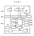
- the folding cellular phone according to Fig. 1 is provided with a hinge driving mechanism to enable the opening/ closing movement of upper and lower units through one-touch operation.
- the upper and lower units of the folding cellular phone automatically open/ close or rotate when receiving a call, a message or the like to inform a user of the receipt of the call or the message, thereby improving the usability and convenience of users.
- the hinge driving mechanism rotates the upper and/ or lower units so as to unfold the body.
- the hinge driving mechanism may rotate (open/ close) the upper and/ or lower units when receiving a call, a message, etc. based on information about the sender of the call or the message (sender information) and/ or the received message (received message information).
- the folding cellular phone with a hinge driving mechanism comprises an upper unit 100, a lower unit 200 and a hinge unit 300.
- the hinge unit 3 00 rotatably connects the edges of the upper unit 100 and the lower unit 200.
- the upper unit 100 has electrical interconnection with the lower unit 200 via FPC, etc. running through the hinge unit 300.
- the upper unit 100 includes a display 101, a speaker 102, an informing speaker 103 and a light sensor 104.
- the display 101, speaker 102, and informing speaker 103 are disposed on the display surface (inside surface) of the upper unit 100, and the light sensor 104 is disposed on the reverse (outside surface).
- the display 101 includes a liquid crystal display (LCD) having a rectangular shape, and displays a wide variety of information and images such as incoming call information.
- the speaker 102 outputs the voice of a calling party during a conversation on the folding cellular phone.
- the informing speaker 103 outputs, for example, a melody signaling an incoming call.
- the light sensor 104 is a unit for detecting the placed condition of the folding cellular phone. More specifically, the light sensor 104 detects whether or not the folding cellular phone is placed on a horizontal plane such as the top of a desk to determine if it is possible or appropriate to open/ close the upper unit 100 and the lower unit 200. Incidentally, other sensors may be used for detecting the placed condition of the folding cellular phone, the light sensor being given only as an example.
- the lower unit 200 includes a controller 201, a motor drive circuit 202, a motor 203, a memory 204, a radio section 205, a transmission/ reception circuit 206, a microphone 207, an operation/ input section 208, a light sensor 209, a battery state detector 210, and a battery 211.
- the operation/ input section 208 and the microphone 207 are disposed on the operation surface (inside surface) of the lower unit 200, and the light sensor 209 is disposed on the reverse (outside surface).
- the operation/ input section 208 is provided with operation keys and switches or buttons as an interface for inputting data or information to use various functions available in the folding cellular phone.
- a user inputs sender information and received message information, registers user settings with respect to the relative positions of the upper and lower units, and switches informing modes with the operation/ input section 208. Examples of informing modes include, but are not limited to call/ mail receive informing mode, battery state informing mode and unacknowledged call informing mode.
- the microphone 207 is a voice input section used when talking on the folding cellular phone.
- the light sensor 209 disposed on the reverse surface of the lower unit 200 is a sensor for detecting the placed condition of the folding cellular phone as with the light sensor 104 of the upper unit 100.
- the controller 201 judges the placed condition of the folding cellular phone based on the result of detection by the light sensors 104 and 209.
- the battery 211 which is a power supply for driving the folding cellular phone, is oriented in the battery chamber in a prescribed direction.
- the controller 201, motor drive circuit 202, motor 203, memory 204, radio section 205, transmission/ reception circuit 206, and battery state detector 210 are disposed inside the lower unit 200.
- the controller 201 controls the respective sections of the folding cellular phone.
- the display 101, informing speaker 103, light sensor 104, motor drive circuit 202, memory 204, radio section 205, operation/ input section 208, light sensor 209, battery state detector 210, an open/ close switch 301 and the like are connected to the controller 201.
- the radio section 205 is a circuit for transmitting/ receiving radio signals to/ from radio base stations via a communications antenna to carry out processes such as the detection of receipt of an incoming call or data (an e-mail message, etc.).
- the transmission/ reception circuit 206 transmits/ receives audio signals to/ from radio base stations during a conversation on the folding cellular phone.
- the transmission/ reception circuit 206 converts voice input through the microphone 207 into voice signals.
- the transmission/ reception circuit 206 converts voice signals into voice, and outputs the voice through the speaker 102.
- the memory 204 stores various information and data such as information on settings for the folding cellular phone, telephone directory information and received messages. Besides, the memory 204 stores sender information for identifying the sender of a call or a message on receipt of the call or the message, priorities of received messages, specific keywords and the like as setting information. The memory 204 also stores user setting information for controlling the opening/ closing movement of the upper and lower units.
- the user setting information includes open/ close positions or rotation angles (angles formed between the upper and lower units) with respect to, for example, each sender or priorities of received messages registered by a user.
- the open/ close switch 301 is located, for example, on the edge of the hinge unit 300.
- a user can open/ close the upper unit 100 and the lower unit 200 at the flip of the open/ close switch 301.
- the motor 203 serving as a hinge driving mechanism and other mechanisms bring the hinge unit 300 to open/ close the upper unit 100 and the lower unit 200 when the open/ close switch 301 is pushed or switched ON/ OFF.
- the motor 203 connected to the motor drive circuit 202 produces a driving force which is applied to an open/ close mechanism (not shown) of the hinge unit 300 to open/ close the upper unit 100 and the lower unit 200.
- the motor drive circuit 202 drives the motor 203 in response to switching operation by the open/ close switch 301 or an instruction from the controller 201 at the time of reception.
- the hinge unit 300 opens/ closes the upper unit 100 and the lower unit 200.
- the hinge unit 300 changes the relative positions of the upper unit 100 and the lower unit 200 (the angle formed between the upper and lower units) or the posture (open/ closed condition) of the folding cellular phone.
- While the motor drive circuit 202 and the motor 203 are disposed inside the lower unit 200 in Fig. 1 , they may be set in the hinge unit 300.
- the battery state detector 210 detects whether or not the battery 211 is being charged and/ or the remaining amount of charge in the battery 211.
- the battery state may be detected in a well known manner.
- the controller 201 controls the motor drive circuit 202 based on whether or not the battery 211 is being charged or the remaining amount of charge in the battery 211 detected by the battery state detector 210 to thereby control the open/ close operation of the hinge unit 300 driven by the motor 203.
- the controller 201 controls the motor drive circuit 202 according to the number of unacknowledged calls (unattended receipt of calls) from the same sender during a prescribed period of time so that the upper unit 100 and the lower unit 200 are located in prescribed relative positions (at a prescribed angle to each other).
- the motor drive circuit 202 drives the motor 203 depending on informing modes under the control of the controller 201 on receipt of a call or a message. Consequently, a driving force is applied to the open/ close mechanism of the hinge unit 300, and the unit 300 opens/ closes (rotates) the upper unit 100 and the lower unit 200 to change the posture of the folding cellular phone. Thus, a user can be informed of the receipt of the call or the message.
- the folding cellular phone may perform conventional informing processes, such as ringing, light emitting, message or image display and the like, in combination with the open/ close or rotative operation.
- the folding cellular phone informs a user of the receipt of a call or a message by opening/ closing the upper unit 100 and the lower unit 200 so that they are located at a prescribed angle to each other based on the sender information and/ or the received message information. That is, the folding cellular phone varies the angle formed between the upper unit 100 and the lower unit 200 according to senders and/ or the types or contents of received messages, which are identifiable by information obtained from incoming calls or received messages. In other words, when the folding cellular phone receives a call from a specific sender, the upper unit 100 and the lower unit 200 are arranged to form an angle associated with the sender therebetween.
- the cellular phone determines whether or not to change the angle formed between the upper unit 100 and the lower unit 200 based on the detection of its placed condition by the light sensors 104 and 209. Concretely, if he folding cellular phone is placed on a desk in closed condition (the upper unit forms an angle of 0° with the lower unit), when receiving a call from a specific sender, the cellular phone informs a user of the receipt of the call by opening the upper unit 100 and the lower unit 200 so that they are located at a prescribed angle, for example, 90° to each other as well as by a ringing tone and information display on the display 101.
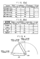
- Setting information such as the open/ close operation setting information shown in Fig. 3 , for controlling the opening/ closing or rotational movement of the upper and lower units on receipt of a call or a message is previously registered with the folding cellular phone of this embodiment. Angles formed between the upper and lower units on receipt of respective calls or messages are determined as the open/ close operation setting information.
- the folding cellular phone may be provided with a prescribed setting interface for allowing a user to make the open/ close operation settings. In this case, the user registers the open/ close operation settings through the setting interface.
- Fig. 3 (a) when receiving a call or a message from a sender included in this table (from a sender who is identified as one of sender numbers "AAA-BBB-CCC" to "MMM-NNN-OOO"), the upper and lower units are opened/ closed so that they form the angle indicated by the open/ close position associated with the sender to inform a user of the receipt of the call or the message.
- the folding cellular phone opens/ closes the upper and lower units so that they form the angle associated with the priority of the received message.
- the upper and lower units are arranged at a greater angle to each other when receiving a message having higher priority.
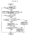
- the open/ close position (1), (2) and (1)' correspond to three types of motor drive control (1), (2) and (1)' shown in the flowchart of Fig. 2 , respectively.
- Tthis is to vary open/ close operation control according to the conditions of the folding cellular phone, such as the placed condition of the cellular phone detected by the light sensors 104 and 209, answering condition (whether or not a user has answered a call) and the like.
- angles formed between the upper unit 100 and the lower unit 200 are shown as the open/ close positions (1), (2) and (1)'.
- the open/ close positions for controlling the opening/ closing movement of the upper and lower units may be set to arbitrary angles, or may be selected from predetermined patterns, as for example those shown in Fig. 3 .
- the upper unit 100 and the lower unit 200 are provided with the light sensors 104 and 209, respectively, on their reverse surfaces exposed to outside when the folding cellular phone is folded.
- the light sensor 104 on the reverse of the upper unit 100 detects "light”
- the light sensor 209 on the reverse of the lower unit 200 detects "dark”
- the battery state detector 210 detects whether or not the battery 211 is being charged and/ or the remaining amount of charge in the battery 211.
- the controller 201 controls the motor drive circuit 202 based on the detection result to control the open/ close mechanism of the hinge unit 300 driven by the motor 203. Thus, a user can be informed as to whether or not the battery 211 is being charged and/ or the remaining amount of charge in the battery 211.
- Setting information such as the open/ close operation setting information shown in Fig. 6 , for determining the movement of the upper and lower units in the informing process is registered with the folding cellular phone in advance as in call/ mail receive informing mode described previously in connection with Fig. 3 .
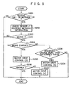
- tree types of open/ close position (3) to (5) correspond to three types of motor drive control (3) to (5) shown in the flowchart of Fig. 5 , respectively.
- the upper unit 100 and the lower unit 200 are arranged in prescribed relative positions according to the number of unacknowledged calls (unattended receipt of calls) from the same sender during a prescribed time period under the control of the controller 201.
- a user can be informed of the presence of unacknowledged calls and the number of unacknowledged calls.
- Setting information such as the open/ close operation setting information shown in Fig. 8 , for determining the movement of the upper and lower units in the informing process is registered with the folding cellular phone in advance as in call/ mail receive informing mode described previously in connection with Fig. 3 .
- three types of open/ close position (6) to (8) correspond to three types of motor drive control (6) to (8) shown in the flowchart of Fig. 7 , respectively.
- the placed condition of the folding cellular phone may be detected without using light sensors and without providing sensors on both the upper unit 100 and the lower unit 200.
- the radio section 205 detects the receipt of a call or a message, and informs the controller 201 about the detection (step S101, Yes).
- the controller 201 checks, for example, the sender number of the call or the message as the sender information and/ or the priority of the message as the received message information (step S102). Subsequently, the controller 201 matches the information obtained from the received call or message with the registered sender information and/ or received message information (open/ close operation setting information) stored in the memory 204 (step S 103).
- step S103, No When the information obtained from the received call or message does not match any of, for example, sender numbers (sender information) and/ or priorities (received message information) stored in the memory 204, that is, when open/ close operation is not required to inform a user of the receipt of the call or the message from the sender (step S103, No), normal informing processes are performed.
- the information obtained from the received call or message matches the sender information and/ or received message information stored in the memory 204, that is, when open/ close operation is required to inform a user of the receipt of the call or the message from the sender (step S 103, Yes)
- the following motor drive control (open/ close operation - informing control) process is carried out.
- the light sensors 104 and 209 detect whether or not the folding cellular phone is placed on a substantially horizontal plane such as the top of a desk. Having determined to perform open/ close operation - informing control process by checking the sender/ received message information, the controller 201 determines if it is possible or appropriate to open/ close the upper unit 100 and the lower unit 200 based on the output of the light sensors 104 and 209 (step S104). Thus, the type of motor drive control is determined (open/ close position (1) or (1)' is selected) based on judgments about the sender/ received message information and the placed condition of the folding cellular phone made at steps S103 and S 104.
- step S104 When the controller 201 has determined that the folding cellular phone is placed on a substantially horizontal plane such as a desk or the like (step S104, Yes), motor drive control (1) is to be executed. When the controller 201 has determined that it is impossible or inappropriate to open/ close the upper unit 100 and the lower unit 200 (step S104, No), motor drive control (1)' is to be executed.
- the controller 201 controls the motor drive circuit 202 and the motor 203 based on the setting information as shown in Fig. 3 so that the upper unit 100 and the lower unit 200 are located in prescribed relative positions or at a prescribed angle to each other (step S105 or S108).
- visual and acoustic informing processes are also performed through the display 101 and the informing speaker 103. That is, the display 101 on the upper unit 100 displays the sender information or the like and the informing speaker 103 outputs the ring tone.
- step S 106, No motor drive control (2) is to be executed.
- the controller 201 controls the motor drive circuit 202 and the motor 203 so that the upper unit 100 and the lower unit 200 are located in prescribed relative positions or at a prescribed angle (open/ close position (2)) to each other (step S107). Thereby, it is possible to inform the user as to the presence of the unacknowledged call by the angle formed between the upper unit 100 and the lower unit 200.
- FIG. 4 An example of open/ close operation control will be explained referring to Fig. 4 .
- the upper unit 100 and the lower unit 200 are opened so as to be at an angle of about 90° (open/ close position (1)) to each other.
- the upper and lower units are arranged at an angle of from 0° to 10° (open/ close position (1)') to each other.
- the upper and lower units are opened at an angle of about 90° (open/ close position (1)) to each other, in the case where the user has not answered the call and motor drive control (2) is executed, the upper and lower units are closed so as to be at an angle of about 60° (open/ close position (2)) to each other to inform the user about the unanswered call.
- the radio section 205 detects the receipt of a call or a message, and informs the controller 201 about the detection (step S201, Yes).
- the controller 201 checks, for example, the sender number of the call or the message as the sender information and/ or the priority of the message as the received message information (step S202). Subsequently, the controller 201 matches the information obtained from the received call or message with the registered sender information and/ or received message information (open/ close operation setting information) stored in the memory 204 (step S203).
- step S203, No When the information obtained from the received call or message does not match any of, for example, sender numbers (sender information) and/ or priorities (received message information) stored in the memory 204, that is, when open/ close operation is not required to inform a user of the receipt of the call or the message from the sender (step S203, No), normal informing processes are performed.
- the information obtained from the received call or message matches the sender information and/ or received message information stored in the memory 204, that is, when open/ close operation is required to inform a user of the receipt of the call or the message from the sender (step S203, Yes)
- the following motor drive control (open/ close operation - informing control) process is carried out.
- the battery state detector 210 detects whether or not the battery 211 is being charged and/ or the remaining amount of charge in the battery 211. Having determined to perform open/ close operation - informing control process by checking the sender/ received message information, the controller 201 determines whether or not the battery 211 is being charged based on the detection result or output from the battery state detector 210 (step S204). When the battery 211 is not being charged, the controller 201 compares the remaining amount of charge in the battery 211 with a predetermined value for judging whether it is possible or appropriate to open/ close the upper unit 100 and the lower unit 200 (step S208).
- the type of motor drive control is determined (open/ close position (3) or (5) is selected) based on judgments about the sender/ received message information and the battery state made at steps S203, S204 and S208.
- the controller 201 controls the motor drive circuit 202 and the motor 203 (step S205 or S209).
- step S204 When the battery 211 of the folding cellular phone is being charged (step S204, Yes), and the user does not answer or acknowledge the call (step S206, No), motor drive control (4) is to be executed. Accordingly, the controller 201 controls the motor drive circuit 202 and the motor 203 so that the upper unit 100 and the lower unit 200 are located in prescribed relative positions or at a prescribed angle (open/ close position (4)) to each other (step S207). Thereby, it is possible to inform the user as to the presence of the unacknowledged call by the angle formed between the upper and lower units.
- the radio section 205 detects the receipt of a call, and informs the controller 201 about the detection (step S301, Yes).
- the controller 201 checks, for example, the sender number of the call as the sender information (step S302), and matches the sender information obtained from the received call with the registered sender information stored in the memory 204 (step S303).
- step S303, No When the information obtained from the received call does not match any of, for example, sender numbers (sender information) stored in the memory 204, that is, when open/ close operation is not required to inform a user of the receipt of the call from the sender (step S303, No), normal informing processes are performed.
- the controller 201 determines whether or not the last call within, for example, 6 hours was an unacknowledged call based on an incoming call history stored in the memory 204.
- step 304, Yes the following motor drive control (open/ close operation - informing control) process is carried out.
- step S305 When the last call was an unacknowledged call, the number of unacknowledged calls from the same sender during a prescribed time period (e.g. 6 hours) is counted with reference to the incoming call history stored in the memory 204 (step S305). In Fig. 7 , when the number of unacknowledged calls is less than 3, motor drive control (6) is to be executed. On the other hand, when there are 3 or more unacknowledged calls, motor drive control (7) is to be executed (steps 5306 and S307).
- a prescribed time period e.g. 6 hours
- step S307 when the user does not answer the call at step S307 (step S308, No), motor drive control (8) is to be executed. Accordingly, the controller 201 controls the motor drive circuit 202 and the motor 203 so that the upper unit 100 and the lower unit 200 are located in prescribed relative positions or at a prescribed angle (open/ close position (8)) to each other (step S309). Thereby, it is possible to inform the user as to the presence of the unacknowledged call by the angle formed between the upper and lower units.
- the user may set an arbitrary number as the threshold.
- the time for counting the number of unacknowledged calls from a specific sender is not limited to 6 hours, and the user may set an arbitrary period of time as the count time.
- the upper unit 100 and the lower unit 200 just move into prescribed relative positions so as to be opened/ closed at a prescribed angle to each other according to setting information, and stay therein.
- the upper and lower units may be repeatedly opened/ closed or rotated prescribed degrees back and forth at prescribed intervals during the informing period.
- the received message information detected by the folding cellular phone is not limited to the priorities of received messages.
- the received message information may be previously specified keywords contained in mail addresses of senders, messages and/ or titles of messages. In this case, open/ close operation can be controlled according to the keywords.
- the placed condition of the cellular phone is detected by sensors, and open/ close operation is performed based on the detection result.
- a user may also switch between normal mode and mode for performing open/ close operation by prescribed input. This allows a user to place the folding cellular phone on a desk or the like as needed and switch modes from normal mode to mode for performing open/ close operation by the input.
- the folding cellular phone may further include a function for stopping open/ close operation when detecting a prescribed reactive force which cause an obstruction to the opening/ closing movement of the upper and lower units. With this function, it is possible to prevent an undesired failure and a malfunction due to such obstruction.
- the present invention can be applied to general portable information terminal equipment, such as PDA (Personal Digital Assistant), which is provided with a radio communication function and comprised of upper and lower units rotatably coupled to one another by a connecting section driven by a connecting section driving mechanism.
- PDA Personal Digital Assistant
- the present invention is applicable to a sliding cellular phone as shown in Figs. 9 and 10 in similar fashion.
- Fig. 9 is an exterior view of a sliding cellular phone with its upper unit 400 and lower unit 500 being open.
- Fig. 10 is an exterior view of the sliding cellular phone in closed condition.
- the sliding cellular phone is provided with a slide structure 600 including slide parts 610 set on the sides of the upper unit 400 and slide rails 620 set on the sides of the lower unit 500 in sliding engagement with the slide parts 610.
- the upper unit 400 and the lower unit 500 are slidably connected to each other by the slide structure 600.
- open/ close positions registered as setting information are set by the distance that the upper unit 400 or lower unit 500 is to be moved as shown in Fig. 11 .
- a controller controls a motor to slide the slide parts 610 along the slide rails 620 a predetermined distance so that the upper unit 400 and the lower unit 500 are arranged in prescribed relative positions. Thereby, a user can be informed of the receipt of the call or the message.
- Fig. 12 is a side view of the sliding cellular phone showing examples of open/ close positions in the sliding movements.
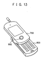
- the present invention is applicable to a turning cellular phone shown in Figs. 13 and 14 in similar fashion, which reflect a turning cellular phone in open condition and in closed condition, respectively.
- the turning cellular phone comprises an upper unit 700, a lower unit 800 and a rotative connector 900 that rotatably supports the upper unit 700 and lower unit 800 on a rotation axis substantially perpendicular to a display surface.
- the upper unit 700 and the lower unit 800 are rotatably connected to each other by the rotative connector 900.
- Fig. 15 shows the application of the present invention to the turning cellular phone, open/ close positions registered as setting information are provided by the angle formed between the upper unit 700 and the lower unit 800 when they are rotated on the axis substantially perpendicular to a display surface.
- a controller When receiving a call or a message, a controller controls a motor to rotate the upper unit 700 and/ or the lower unit 800 on the rotative connector 900 so that they are located at a prescribed angle to each other. Thereby, a user can be informed of the receipt of the call or the message.
- Fig. 16 is an overhead view of the turning cellular phone showing examples of open/ close positions in the rotational movements.
Landscapes
- Engineering & Computer Science (AREA)
- Signal Processing (AREA)
- Physics & Mathematics (AREA)
- General Physics & Mathematics (AREA)
- Telephone Set Structure (AREA)
- Telephone Function (AREA)
- Mobile Radio Communication Systems (AREA)
Claims (14)
- Tragbares Informationsendgerät, umfassend:zwei Einheiten (100, 200);einen Verbindungsabschnitt (300) zum Verbinden der beiden Einheiten (100, 200) miteinander zur relativen Bewegung;einen Verbindungsabschnittsantriebsmechanismus (203) zum Ändern der relativen Positionen der beiden Einheiten (100, 200), um die Einheiten (100, 200) zu öffnen/schließen;gekennzeichnet durch
eine Steuereinrichtung (201) zum Steuern des Verbindungsabschnittsantriebsmechanismus (203), um, wenn ein Anruf oder eine Nachricht empfangen wird, basierend auf Informationen über den Sender des Anrufs oder der Nachricht und/oder über die empfangene Nachricht eine oder beide Einheiten (100, 200) so zu bewegen, so dass sie sich in vorgeschriebenen relativen Positionen befinden, um dadurch einen Benutzer über den Empfang des Anrufs oder der Nachricht zu informieren. - Gerät nach Anspruch 1, wobei die Steuereinrichtung (201) eine Steuerung der Offnungs-/Schließfunktion vorsieht, so dass sich die beiden Einheiten (100, 200) in vorgeschriebenen relativen Position befinden, wenn ein eingehender Anruf nicht entgegen genommen wird.
- Gerät nach einem der Ansprüche 1 oder 2, weiterhin umfassend einen Detektor (104) zum Erkennen des Platzierungszustands des Geräts, wobei
die Steuereinrichtung (201) basierend auf dem von dem Detektor (104) erkannten Platzierungszustand des Geräts eine Steuerung der Offnungs-/Schließfunktion vorsieht. - Gerät nach einem der Ansprüche 1 bis 3, weiterhin umfassend eine Einstell-Schnittstelle (208) zum Registrieren von Benutzereinstellungen bezogen auf die Senderinformationen, Informationen der empfangenen Nachricht und die relativen Positionen der beiden Einheiten (100, 200), wobei
die Steuereinrichtung (201) den Verbindungsabschnittsantriebsmechanismus (203) so steuert, dass die relativen Positionen der Einheiten (100, 200) basierend auf den Benutzereinstellungen geändert werden, wenn ein Anruf oder eine Nachricht empfangen wird. - Gerät nach einem der Ansprüche 1 bis 4, wobei sich die beiden Einheiten (100, 200) durch die Steuerung der Steuereinrichtung (201) in vorgeschriebenen Intervallen wiederholt öffnen/schließen.
- Gerät nach einem der Ansprüche 1 bis 5, weiterhin umfassend einen Batteriezustandsdetektor (210) zum Erkennen, ob eine Batterie (211), die eine Leistungsversorgung zum Antreiben des Geräts ist, geladen wird und/oder zum Erkennen der verbleibenden Ladungsmenge in der Batterie (211), wobei:die Steuereinrichtung (201) den Verbindungsabschnittsantriebsmechanismus (203) basierend auf dem Ergebnis der Erkennung durch den Batteriezustandsdetektor (210) steuert.
- Gerät nach einem der Ansprüche 1 bis 6, wobei, die beiden Einheiten (100, 200), wenn ein eingehender Anruf nicht entgegen genommen wird, durch die Steuerung der Steuereinrichtung (201) entsprechend der Anzahl von nicht entgegen genommenen Anrufen von dem gleichen Sender während einer vorgeschriebenen Zeitdauer in vorgeschriebenen relativen Positionen angeordnet werden.
- Gerät nach einem der Ansprüche 1 bis 7, wobei:der Verbindungsabschnitt (300) eine Gleitstruktur aufweist, die Gleitschienen (620), die an einer der Einheiten (100, 200) angebracht sind, und Gleitteile (610), die an der anderen Einheit angebracht sind, in Gleiteingriff mit der Gleitschiene (620) umfasst; undder Verbindungsabschnittsantriebsmechanismus (203) die relativen Positionen der beiden Einheiten (100, 200) ändert, indem die Einheit mit den Gleitteilen entlang den Gleitschienen gleitet.
- Gerät nach einem der Ansprüche 1 bis 8, wobei:der Verbindungsabschnitt (300) die beiden Einheiten (100, 200) drehbar auf einer Rotationsachse (900) trägt, die im Wesentlichen senkrecht zu einer Anzeigeoberfläche ist; undder Verbindungsabschnittsantriebsmechanismus (203) die relativen Positionen der beiden Einheiten ändert, indem mindestens eine der Einheiten auf der Rotationsachse (900) gedreht wird.
- Gerät nach Anspruch 1, wobei
die beiden Einheiten als obere und untere Einheiten (100, 200) gebildet sind,
die obere und untere Einheit (100, 200) durch eine Gelenkeinheit (300), die den Verbindungsabschnitt (300) bildet, miteinander gekoppelt sind;
der Verbindungsabschnittsantriebsmechanismus (203) als Gelenkantriebsmechanismus (203) zum Ändern der relativen Positionen der oberen und unteren Einheiten (100, 200) gebildet ist, indem eine oder beide Einheiten (100, 200) gedreht werden; und
eine Steuereinrichtung (201) zum Steuern des Gelenkantriebsmechanismus (203) eingerichtet ist, um, wenn ein Anruf oder eine Nachricht empfangen wird, basierend auf Informationen über den Sender des Anrufs oder der Nachricht und/oder über die empfangene Nachricht eine oder beide Einheiten (100, 200) so zu drehen, dass sie sich in einem vorbestimmten Winkel zueinander befinden, um dadurch einen Benutzer über den Empfang des Anrufs oder der Nachricht zu informieren. - Gerät nach Anspruch 10, wobei die Steuereinrichtung (201) eine Steuerung der Öffnungs-/Schließfunktion so vorsieht, dass sich die obere und untere Einheit (100, 200) in einem vorgeschriebenen Winkel zueinander befinden, wenn ein eingehender Anruf nicht bestätigt wird.
- Gerät nach Anspruch 10 oder 11, weiterhin umfassend einen Detektor (104) zum Erkennen des Platzierungszustands des Geräts, wobei
die Steuereinrichtung (201) basierend auf dem von dem Detektor (104) erkannten Platzierungszustand des Geräts eine Steuerung der Öffnungs-/Schließfunktion vorsieht. - Gerät nach einem der Ansprüche 10 bis 12, weiterhin umfassend eine Einstell-Schnittstelle (208) zum Registrieren von Benutzereinstellungen bezogen auf Öffnungs-/Schließpositionen, die den Senderinformationen und/oder Informationen über die empfangene Nachricht zugeordnet sind, wobei
die Steuereinrichtung (201) den Gelenkantriebsmechanismus (203) so steuert, dass der zwischen der oberen und unteren Einheit (100, 200) gebildete Winkel basierend auf den Benutzereinstellungen geändert wird, wenn ein Anruf oder eine Nachricht empfangen wird. - Gerät nach einem der Ansprüche 10 bis 13, wobei sich die obere und untere Einheit (100, 200) durch die Steuerung der Steuereinrichtung (201) in vorgeschriebenen Intervallen wiederholt öffnen/schließen.
Applications Claiming Priority (4)
| Application Number | Priority Date | Filing Date | Title |
|---|---|---|---|
| JP2002316655 | 2002-10-30 | ||
| JP2002316655 | 2002-10-30 | ||
| JP2003303568A JP4125653B2 (ja) | 2002-10-30 | 2003-08-27 | 携帯型情報端末装置 |
| JP2003303568 | 2003-08-27 |
Publications (3)
| Publication Number | Publication Date |
|---|---|
| EP1422913A2 EP1422913A2 (de) | 2004-05-26 |
| EP1422913A3 EP1422913A3 (de) | 2006-02-01 |
| EP1422913B1 true EP1422913B1 (de) | 2011-09-14 |
Family
ID=32232656
Family Applications (1)
| Application Number | Title | Priority Date | Filing Date |
|---|---|---|---|
| EP03090373A Expired - Lifetime EP1422913B1 (de) | 2002-10-30 | 2003-10-30 | Tragbares Informationsendgerät |
Country Status (4)
| Country | Link |
|---|---|
| US (4) | US7136686B2 (de) |
| EP (1) | EP1422913B1 (de) |
| JP (1) | JP4125653B2 (de) |
| CN (2) | CN101030989B (de) |
Families Citing this family (36)
| Publication number | Priority date | Publication date | Assignee | Title |
|---|---|---|---|---|
| US8155718B2 (en) * | 2003-09-03 | 2012-04-10 | Samsung Electronics Co., Ltd. | Sliding/hinge apparatus for sliding/rotating type mobile terminals |
| US7529571B2 (en) * | 2003-09-03 | 2009-05-05 | Samsung Electronics Co., Ltd. | Sliding/hinge apparatus for sliding/rotating type mobile terminals |
| USD539773S1 (en) * | 2003-12-11 | 2007-04-03 | Samsung Electronics Co. | Portable telephone |
| KR100616544B1 (ko) * | 2004-04-30 | 2006-08-29 | 삼성전기주식회사 | 슬라이드형 이동통신단말기 및 그 자동구동방법 |
| US20050282595A1 (en) * | 2004-06-21 | 2005-12-22 | Spence Michael F | Communication device including one or more electrical control buttons in an upper housing part |
| JP4403398B2 (ja) * | 2004-09-08 | 2010-01-27 | ソニー株式会社 | 情報処理装置、情報処理方法、およびプログラム |
| WO2006051580A1 (ja) * | 2004-11-09 | 2006-05-18 | Matsushita Electric Industrial Co., Ltd. | 折り畳み式携帯電話機 |
| TWI253895B (en) * | 2005-01-28 | 2006-04-21 | Benq Corp | Sliding and rotation complex mechanism of a handheld communication device |
| JP2007036636A (ja) * | 2005-07-27 | 2007-02-08 | Nec Saitama Ltd | 携帯電話端末 |
| US20070060219A1 (en) * | 2005-09-09 | 2007-03-15 | Hung-Chih Lin | Sliding shell |
| JP2007104275A (ja) * | 2005-10-04 | 2007-04-19 | Nec Corp | 回動自在型携帯通信機器及び回動自在型携帯電話機 |
| US7660609B2 (en) | 2005-12-07 | 2010-02-09 | Sony Ericsson Mobile Communications Ab | Persistent tactile event notification |
| USD555132S1 (en) * | 2006-05-15 | 2007-11-13 | Samsung Electronics Co., Ltd. | Mobile phone |
| USD555131S1 (en) * | 2006-05-15 | 2007-11-13 | Samsung Electronics Co., Ltd. | Mobile phone |
| JP4583392B2 (ja) * | 2007-02-19 | 2010-11-17 | 京セラ株式会社 | 携帯端末の制御方法 |
| US20100295801A1 (en) * | 2007-04-10 | 2010-11-25 | Nokia Corporation | Electronic devices |
| US20080252476A1 (en) * | 2007-04-12 | 2008-10-16 | Motorola, Inc. | Closeable communications device and method for automatically opening such a device |
| JP2009111878A (ja) * | 2007-10-31 | 2009-05-21 | Fujifilm Corp | 携帯機器及び撮像装置 |
| US20090312000A1 (en) * | 2008-06-13 | 2009-12-17 | Sony Ericsson Mobile Communicatins Ab | Environment responsive mobile communication device operation |
| US20100007510A1 (en) * | 2008-07-14 | 2010-01-14 | Sony Ericsson Mobile Communications Ab | Communication device with orientation indication of receipt of communication signal |
| US8400065B2 (en) | 2008-09-02 | 2013-03-19 | Research In Motion Limited | Dual light sensors on a portable electronic device |
| TWM356326U (en) * | 2008-12-26 | 2009-05-01 | Inventec Appliances Corp | Cellular phone |
| CN101833354B (zh) * | 2009-03-13 | 2013-07-31 | 鸿富锦精密工业(深圳)有限公司 | 旋转控制系统及方法 |
| USD615055S1 (en) * | 2009-06-09 | 2010-05-04 | Samsung Electronics Co., Ltd. | Mobile phone |
| EP2315186B1 (de) * | 2009-10-26 | 2016-09-21 | Lg Electronics Inc. | Mobiles Terminal mit flexiblem Gehäuse zur Eingabe eines Signals beim Biegen des Gehäuses |
| US8320961B2 (en) * | 2009-12-30 | 2012-11-27 | Nokia Corporation | Apparatus for a tangible interface |
| USD645835S1 (en) * | 2010-09-03 | 2011-09-27 | Samsung Electronics Co., Ltd. | Mobile phone |
| USD645012S1 (en) * | 2010-09-09 | 2011-09-13 | Samsung Electronics Co., Ltd. | Mobile phone |
| USD644197S1 (en) * | 2010-09-15 | 2011-08-30 | Samsung Electronics Co., Ltd. | Mobile phone |
| US8504114B1 (en) * | 2010-12-03 | 2013-08-06 | Google Inc. | Intelligent notifications with dynamic escalations |
| US20130082840A1 (en) * | 2011-10-03 | 2013-04-04 | Research In Motion Limited | Method and Apparatus Pertaining to Automatically Moving a Component that Comprises a Part of a Portable Electronic Device |
| TW201435547A (zh) * | 2013-03-07 | 2014-09-16 | Hon Hai Prec Ind Co Ltd | 電子裝置 |
| EP3230819B1 (de) * | 2014-12-08 | 2020-07-29 | Telefonaktiebolaget LM Ericsson (publ) | Vorrichtung und verfahren, um einem benutzer zu ermöglichen, eine tragbare vorrichtung zu ergreifen |
| WO2017061210A1 (ja) * | 2015-10-07 | 2017-04-13 | シャープ株式会社 | 報知制御装置および報知制御装置の制御方法 |
| TW201939808A (zh) * | 2018-03-02 | 2019-10-01 | 和碩聯合科技股份有限公司 | 天線功率調整方法 |
| CN118675409A (zh) * | 2023-03-15 | 2024-09-20 | 摩托罗拉移动有限责任公司 | 可卷曲屏设备热缓解 |
Family Cites Families (28)
| Publication number | Priority date | Publication date | Assignee | Title |
|---|---|---|---|---|
| JP2689880B2 (ja) | 1993-12-28 | 1997-12-10 | 日本電気株式会社 | 携帯電話機 |
| JPH07288860A (ja) | 1994-04-18 | 1995-10-31 | Canon Inc | 携帯無線電話機 |
| JP2595932B2 (ja) * | 1994-05-18 | 1997-04-02 | 日本電気株式会社 | 携帯無線機 |
| JPH11187087A (ja) | 1997-12-17 | 1999-07-09 | Toshiba Corp | 着信バイブレータ機能付き通信機器 |
| US6020878A (en) * | 1998-06-01 | 2000-02-01 | Motorola, Inc. | Selective call radio with hinged touchpad |
| CA2349600C (en) * | 1998-12-28 | 2005-02-08 | Fujitsu Limited | Three-dimensional skeleton data error absorbing apparatus |
| JP2000253113A (ja) * | 1999-02-26 | 2000-09-14 | Hitachi Ltd | 情報通信端末装置 |
| JP4203782B2 (ja) * | 1999-05-19 | 2009-01-07 | ソニー株式会社 | 情報処理装置及びバッテリ |
| GB2350516A (en) * | 1999-05-26 | 2000-11-29 | Ericsson Telefon Ab L M | Telephone handset with at least two movable elements whose motion is linked or is initiated by pushbutton or incoming call |
| JP2001045124A (ja) * | 1999-07-30 | 2001-02-16 | Sony Corp | 情報端末 |
| JP2001203791A (ja) * | 2000-01-18 | 2001-07-27 | Strawberry Corporation:Kk | 携帯式電話に付設されるフリップの開閉構造 |
| JP3530475B2 (ja) * | 2000-09-25 | 2004-05-24 | 三洋電機株式会社 | 折畳式通信端末装置および情報表示方法 |
| US6714403B2 (en) * | 2000-11-22 | 2004-03-30 | Alps Electric Co., Ltd. | Foldable keyboard input device |
| KR100369653B1 (ko) | 2001-02-16 | 2003-01-30 | 삼성전자 주식회사 | 자동 및 수동 겸용 접이형 휴대용 무선단말기에서의서브바디 개폐 제어방법 및 장치 |
| JP2002271464A (ja) | 2001-03-07 | 2002-09-20 | Etsuko Takahashi | 開閉動作によって電波着信を知らせる折りたたみ式携帯電話機 |
| JP2002281116A (ja) | 2001-03-16 | 2002-09-27 | Nec Access Technica Ltd | 折り畳み式携帯通信機器 |
| US6907276B2 (en) | 2001-03-21 | 2005-06-14 | Nec Corporation | Mobile communication terminal with external display unit |
| JP4071452B2 (ja) * | 2001-04-13 | 2008-04-02 | 松下電器産業株式会社 | 携帯無線機 |
| US6842627B2 (en) * | 2001-05-18 | 2005-01-11 | Nokia Mobile Phones Limited | Portable electronic device multipart housing electrical connection |
| JP3686845B2 (ja) * | 2001-05-21 | 2005-08-24 | 埼玉日本電気株式会社 | 折り畳み型携帯電話機 |
| JP4496669B2 (ja) * | 2001-05-24 | 2010-07-07 | 日本電気株式会社 | 無線携帯端末装置 |
| JP2003008695A (ja) * | 2001-06-25 | 2003-01-10 | Pioneer Electronic Corp | 携帯情報端末機 |
| JP3729161B2 (ja) * | 2001-08-07 | 2005-12-21 | カシオ計算機株式会社 | 目標位置探索装置、目標位置探索方法及びプログラム |
| JP2003174495A (ja) * | 2001-09-28 | 2003-06-20 | Nec Corp | 折り畳み式携帯情報端末 |
| KR100403370B1 (ko) * | 2001-09-29 | 2003-11-01 | 삼성전자주식회사 | 피디에이 겸용 무선 단말기의 사용자 인터페이싱 장치 |
| JP2003244293A (ja) * | 2002-02-14 | 2003-08-29 | Nec Corp | 折り畳み式携帯情報端末 |
| JP2003298698A (ja) * | 2002-03-29 | 2003-10-17 | Nec Corp | 折り畳み式携帯情報端末 |
| US7292879B2 (en) | 2002-12-27 | 2007-11-06 | Matorola, Inc. | Method and apparatus of alerting a user of a mobile electronic device |
-
2003
- 2003-08-27 JP JP2003303568A patent/JP4125653B2/ja not_active Expired - Fee Related
- 2003-10-27 CN CN2007100920916A patent/CN101030989B/zh not_active Expired - Fee Related
- 2003-10-27 CN CNB2003101043843A patent/CN100454925C/zh not_active Expired - Fee Related
- 2003-10-28 US US10/693,920 patent/US7136686B2/en not_active Expired - Fee Related
- 2003-10-30 EP EP03090373A patent/EP1422913B1/de not_active Expired - Lifetime
-
2006
- 2006-10-10 US US11/544,589 patent/US7756555B2/en not_active Expired - Fee Related
-
2010
- 2010-05-13 US US12/779,352 patent/US8041406B2/en not_active Expired - Fee Related
-
2011
- 2011-09-19 US US13/235,849 patent/US8442599B2/en not_active Expired - Fee Related
Also Published As
| Publication number | Publication date |
|---|---|
| CN100454925C (zh) | 2009-01-21 |
| JP4125653B2 (ja) | 2008-07-30 |
| JP2004173233A (ja) | 2004-06-17 |
| US20120028689A1 (en) | 2012-02-02 |
| US7136686B2 (en) | 2006-11-14 |
| US8442599B2 (en) | 2013-05-14 |
| EP1422913A3 (de) | 2006-02-01 |
| US20070032263A1 (en) | 2007-02-08 |
| US20040259609A1 (en) | 2004-12-23 |
| US7756555B2 (en) | 2010-07-13 |
| CN101030989B (zh) | 2011-03-30 |
| EP1422913A2 (de) | 2004-05-26 |
| CN101030989A (zh) | 2007-09-05 |
| US8041406B2 (en) | 2011-10-18 |
| CN1499807A (zh) | 2004-05-26 |
| US20100222114A1 (en) | 2010-09-02 |
Similar Documents
| Publication | Publication Date | Title |
|---|---|---|
| EP1422913B1 (de) | Tragbares Informationsendgerät | |
| KR100438010B1 (ko) | 폴더식 통신단말장치 및 정보표시방법 | |
| KR100703351B1 (ko) | 스윙 타입 휴대 장치 | |
| CN100463463C (zh) | 便携式通信终端设备 | |
| JP2002152346A (ja) | 折り畳み式携帯通信端末装置 | |
| US7321789B2 (en) | Folding information processor | |
| EP1519544A2 (de) | Vorrichtung und Verfahren zur Steuerung eines verschiebbaren und tragbaren Mobiltelefon | |
| US20040235540A1 (en) | Portable terminal unit | |
| KR100810353B1 (ko) | 게임 겸용 휴대 통신 단말기 및 그의 사용자 인터페이싱장치 | |
| EP1345389B1 (de) | Zusammenklappbares funkgerät, gesprächsstartverfahren und gesprächsstartprogramm | |
| JP4029902B2 (ja) | 携帯型情報端末装置 | |
| JP2003333139A (ja) | 折り畳み式携帯情報端末 | |
| KR100405141B1 (ko) | 폴더형 이동 통신 단말기의 엘 씨 디 구동 방법 및 그 장치 | |
| KR100594000B1 (ko) | 폴더의 오픈 방향에 따라 동작 모드를 전환하는 이동 통신단말기 및 그 방법 | |
| JP2004312631A (ja) | 折畳式携帯電話装置 | |
| KR200376791Y1 (ko) | 슬라이드 폴더형 이동통신 단말기 | |
| JP3680777B2 (ja) | 携帯電話機 | |
| JP2006074248A (ja) | 携帯端末 | |
| EP1480417A1 (de) | Klappbares mobiles Endgerät mit einer flexibler Anzeigeeinheit | |
| JP4151847B2 (ja) | 携帯通信端末及びレシーバー動作制御方法 | |
| JP2001333167A (ja) | 折り畳み式携帯電話機 | |
| JP4152244B2 (ja) | 通信装置 | |
| KR20040026203A (ko) | 폴더용 휴대전화기 | |
| JP2005210516A (ja) | 携帯通信端末 | |
| JP2006087128A (ja) | 折り畳み式携帯電話機 |
Legal Events
| Date | Code | Title | Description |
|---|---|---|---|
| PUAI | Public reference made under article 153(3) epc to a published international application that has entered the european phase |
Free format text: ORIGINAL CODE: 0009012 |
|
| AK | Designated contracting states |
Kind code of ref document: A2 Designated state(s): AT BE BG CH CY CZ DE DK EE ES FI FR GB GR HU IE IT LI LU MC NL PT RO SE SI SK TR |
|
| AX | Request for extension of the european patent |
Extension state: AL LT LV MK |
|
| PUAL | Search report despatched |
Free format text: ORIGINAL CODE: 0009013 |
|
| AK | Designated contracting states |
Kind code of ref document: A3 Designated state(s): AT BE BG CH CY CZ DE DK EE ES FI FR GB GR HU IE IT LI LU MC NL PT RO SE SI SK TR |
|
| AX | Request for extension of the european patent |
Extension state: AL LT LV MK |
|
| 17P | Request for examination filed |
Effective date: 20060131 |
|
| AKX | Designation fees paid |
Designated state(s): DE FR GB IT |
|
| 17Q | First examination report despatched |
Effective date: 20100908 |
|
| GRAP | Despatch of communication of intention to grant a patent |
Free format text: ORIGINAL CODE: EPIDOSNIGR1 |
|
| GRAS | Grant fee paid |
Free format text: ORIGINAL CODE: EPIDOSNIGR3 |
|
| GRAA | (expected) grant |
Free format text: ORIGINAL CODE: 0009210 |
|
| AK | Designated contracting states |
Kind code of ref document: B1 Designated state(s): DE FR GB IT |
|
| REG | Reference to a national code |
Ref country code: GB Ref legal event code: FG4D |
|
| REG | Reference to a national code |
Ref country code: DE Ref legal event code: R096 Ref document number: 60338340 Country of ref document: DE Effective date: 20111103 |
|
| PG25 | Lapsed in a contracting state [announced via postgrant information from national office to epo] |
Ref country code: IT Free format text: LAPSE BECAUSE OF FAILURE TO SUBMIT A TRANSLATION OF THE DESCRIPTION OR TO PAY THE FEE WITHIN THE PRESCRIBED TIME-LIMIT Effective date: 20110914 |
|
| PLBE | No opposition filed within time limit |
Free format text: ORIGINAL CODE: 0009261 |
|
| STAA | Information on the status of an ep patent application or granted ep patent |
Free format text: STATUS: NO OPPOSITION FILED WITHIN TIME LIMIT |
|
| 26N | No opposition filed |
Effective date: 20120615 |
|
| REG | Reference to a national code |
Ref country code: DE Ref legal event code: R097 Ref document number: 60338340 Country of ref document: DE Effective date: 20120615 |
|
| REG | Reference to a national code |
Ref country code: GB Ref legal event code: 732E Free format text: REGISTERED BETWEEN 20130103 AND 20130109 |
|
| PGFP | Annual fee paid to national office [announced via postgrant information from national office to epo] |
Ref country code: FR Payment date: 20121018 Year of fee payment: 10 Ref country code: DE Payment date: 20121024 Year of fee payment: 10 |
|
| REG | Reference to a national code |
Ref country code: FR Ref legal event code: TP Owner name: WARREN & LEWIS INVESTMENT CORPORATION, US Effective date: 20130102 |
|
| PGFP | Annual fee paid to national office [announced via postgrant information from national office to epo] |
Ref country code: GB Payment date: 20121024 Year of fee payment: 10 |
|
| REG | Reference to a national code |
Ref country code: DE Ref legal event code: R081 Ref document number: 60338340 Country of ref document: DE Owner name: WARREN & LEWIS INVESTMENT CORPORATION, US Free format text: FORMER OWNER: NEC CORP., TOKYO, JP Effective date: 20110915 Ref country code: DE Ref legal event code: R081 Ref document number: 60338340 Country of ref document: DE Owner name: WARREN & LEWIS INVESTMENT CORPORATION, US Free format text: FORMER OWNER: NEC CORPORATION, MINATO-KU, JP Effective date: 20130912 Ref country code: DE Ref legal event code: R082 Ref document number: 60338340 Country of ref document: DE Representative=s name: STORK BAMBERGER PATENTANWAELTE, DE Effective date: 20130912 Ref country code: DE Ref legal event code: R081 Ref document number: 60338340 Country of ref document: DE Owner name: WARREN & LEWIS INVESTMENT CORPORATION, FALLS C, US Free format text: FORMER OWNER: NEC CORP., TOKYO, JP Effective date: 20110915 Ref country code: DE Ref legal event code: R081 Ref document number: 60338340 Country of ref document: DE Owner name: WARREN & LEWIS INVESTMENT CORPORATION, FALLS C, US Free format text: FORMER OWNER: NEC CORPORATION, MINATO-KU, TOKYO 108-8001, JP Effective date: 20130912 Ref country code: DE Ref legal event code: R081 Ref document number: 60338340 Country of ref document: DE Owner name: WARREN & LEWIS INVESTMENT CORPORATION, FALLS C, US Free format text: FORMER OWNER: NEC CORPORATION, TOKYO, JP Effective date: 20130912 Ref country code: DE Ref legal event code: R082 Ref document number: 60338340 Country of ref document: DE Representative=s name: STORK BAMBERGER PATENTANWAELTE PARTMBB, DE Effective date: 20130912 |
|
| GBPC | Gb: european patent ceased through non-payment of renewal fee |
Effective date: 20131030 |
|
| REG | Reference to a national code |
Ref country code: DE Ref legal event code: R119 Ref document number: 60338340 Country of ref document: DE Effective date: 20140501 |
|
| PG25 | Lapsed in a contracting state [announced via postgrant information from national office to epo] |
Ref country code: GB Free format text: LAPSE BECAUSE OF NON-PAYMENT OF DUE FEES Effective date: 20131030 |
|
| REG | Reference to a national code |
Ref country code: FR Ref legal event code: ST Effective date: 20140630 |
|
| PG25 | Lapsed in a contracting state [announced via postgrant information from national office to epo] |
Ref country code: FR Free format text: LAPSE BECAUSE OF NON-PAYMENT OF DUE FEES Effective date: 20131031 Ref country code: DE Free format text: LAPSE BECAUSE OF NON-PAYMENT OF DUE FEES Effective date: 20140501 |