EP1422421A2 - Méthode et dispositif d'arrêt et de redémarrage d'un moteur à combustion interne - Google Patents
Méthode et dispositif d'arrêt et de redémarrage d'un moteur à combustion interne Download PDFInfo
- Publication number
- EP1422421A2 EP1422421A2 EP02102629A EP02102629A EP1422421A2 EP 1422421 A2 EP1422421 A2 EP 1422421A2 EP 02102629 A EP02102629 A EP 02102629A EP 02102629 A EP02102629 A EP 02102629A EP 1422421 A2 EP1422421 A2 EP 1422421A2
- Authority
- EP
- European Patent Office
- Prior art keywords
- engine
- torque
- internal combustion
- combustion engine
- crankshaft
- Prior art date
- Legal status (The legal status is an assumption and is not a legal conclusion. Google has not performed a legal analysis and makes no representation as to the accuracy of the status listed.)
- Granted
Links
Images


Classifications
-
- F—MECHANICAL ENGINEERING; LIGHTING; HEATING; WEAPONS; BLASTING
- F02—COMBUSTION ENGINES; HOT-GAS OR COMBUSTION-PRODUCT ENGINE PLANTS
- F02N—STARTING OF COMBUSTION ENGINES; STARTING AIDS FOR SUCH ENGINES, NOT OTHERWISE PROVIDED FOR
- F02N19/00—Starting aids for combustion engines, not otherwise provided for
- F02N19/005—Aiding engine start by starting from a predetermined position, e.g. pre-positioning or reverse rotation
-
- F—MECHANICAL ENGINEERING; LIGHTING; HEATING; WEAPONS; BLASTING
- F02—COMBUSTION ENGINES; HOT-GAS OR COMBUSTION-PRODUCT ENGINE PLANTS
- F02D—CONTROLLING COMBUSTION ENGINES
- F02D41/00—Electrical control of supply of combustible mixture or its constituents
- F02D41/02—Circuit arrangements for generating control signals
- F02D41/04—Introducing corrections for particular operating conditions
- F02D41/042—Introducing corrections for particular operating conditions for stopping the engine
-
- F—MECHANICAL ENGINEERING; LIGHTING; HEATING; WEAPONS; BLASTING
- F02—COMBUSTION ENGINES; HOT-GAS OR COMBUSTION-PRODUCT ENGINE PLANTS
- F02D—CONTROLLING COMBUSTION ENGINES
- F02D41/00—Electrical control of supply of combustible mixture or its constituents
- F02D41/02—Circuit arrangements for generating control signals
- F02D41/04—Introducing corrections for particular operating conditions
- F02D41/06—Introducing corrections for particular operating conditions for engine starting or warming up
- F02D41/062—Introducing corrections for particular operating conditions for engine starting or warming up for starting
- F02D41/064—Introducing corrections for particular operating conditions for engine starting or warming up for starting at cold start
-
- F—MECHANICAL ENGINEERING; LIGHTING; HEATING; WEAPONS; BLASTING
- F02—COMBUSTION ENGINES; HOT-GAS OR COMBUSTION-PRODUCT ENGINE PLANTS
- F02D—CONTROLLING COMBUSTION ENGINES
- F02D41/00—Electrical control of supply of combustible mixture or its constituents
- F02D41/009—Electrical control of supply of combustible mixture or its constituents using means for generating position or synchronisation signals
- F02D2041/0095—Synchronisation of the cylinders during engine shutdown
-
- F—MECHANICAL ENGINEERING; LIGHTING; HEATING; WEAPONS; BLASTING
- F02—COMBUSTION ENGINES; HOT-GAS OR COMBUSTION-PRODUCT ENGINE PLANTS
- F02N—STARTING OF COMBUSTION ENGINES; STARTING AIDS FOR SUCH ENGINES, NOT OTHERWISE PROVIDED FOR
- F02N11/00—Starting of engines by means of electric motors
- F02N11/04—Starting of engines by means of electric motors the motors being associated with current generators
-
- F—MECHANICAL ENGINEERING; LIGHTING; HEATING; WEAPONS; BLASTING
- F02—COMBUSTION ENGINES; HOT-GAS OR COMBUSTION-PRODUCT ENGINE PLANTS
- F02N—STARTING OF COMBUSTION ENGINES; STARTING AIDS FOR SUCH ENGINES, NOT OTHERWISE PROVIDED FOR
- F02N11/00—Starting of engines by means of electric motors
- F02N11/08—Circuits or control means specially adapted for starting of engines
- F02N11/0814—Circuits or control means specially adapted for starting of engines comprising means for controlling automatic idle-start-stop
-
- F—MECHANICAL ENGINEERING; LIGHTING; HEATING; WEAPONS; BLASTING
- F02—COMBUSTION ENGINES; HOT-GAS OR COMBUSTION-PRODUCT ENGINE PLANTS
- F02N—STARTING OF COMBUSTION ENGINES; STARTING AIDS FOR SUCH ENGINES, NOT OTHERWISE PROVIDED FOR
- F02N19/00—Starting aids for combustion engines, not otherwise provided for
- F02N19/005—Aiding engine start by starting from a predetermined position, e.g. pre-positioning or reverse rotation
- F02N2019/008—Aiding engine start by starting from a predetermined position, e.g. pre-positioning or reverse rotation the engine being stopped in a particular position
Definitions
- the invention relates to a method of controlledly shutting down and restarting an internal combustion engine, wherein the internal combustion engine is stopped in a predetermined rest condition. Moreover, the invention relates to an internal combustion engine and a control system for controlledly shutting down and restarting an internal combustion engine, comprising means for stopping an internal combustion engine in a predetermined rest condition.
- WO 01/48373 A1 A method and a device for the controlled shutting down and restarting of an internal combustion engine are described in WO 01/48373 A1. According to that document the engine is actively or passively positioned at a predetermined cranking angle at rest which is stored and later available at restart. The predetermined resting angle is then used to initiate cylinder-specific fuel injection and ignition.
- the total motoring torque increases as the temperature decreases.
- a starter with enough low-speed torque to overcome the torque peaks at low temperatures.
- a smaller electric machine would be sufficient, but it is necessary to install a larger, over-dimensioned machine to cover the entire range of operating temperatures encountered by a vehicle. If the size of the electric machine for cold weather starts could be reduced, a smaller and cheaper electric machine could be implemented.
- a method for controlledly shutting down and restarting an internal combustion engine wherein the internal combustion engine is stopped in a predetermined rest condition.
- the method is characterised in that the predetermined rest condition is so selected that the average motoring torque is decreasing during the first phase in the starting procedure.
- the predetermined rest condition of the internal combustion engine is chosen such that the motoring torque is at or just beyond its minimum in this state. In this way a maximal amount of kinetic energy can be stored in the system by the starter before the following peak of motoring torque is reached.
- the engine is preferably positioned in the predetermined rest condition just after it has been shut down in order to take advantage of the lower motoring torque associated with warm operating temperatures.
- the prepositioning of the engine can be done by a starter which due to battery power limitations at low temperatures would be too weak for this movement in a cold state of the engine.
- the torque and/or the cranking angle may be measured, especially during the positioning of the engine.
- crankshaft of the engine is preferably locked in the rest condition.
- an Integrated Starter Generator can be operated like a starter motor that transforms electrical energy into mechanical energy or vice versa as a generator that produces electricity from mechanical movement.
- Integrated Starter Generators are typically coupled to the crankshaft with a rather low transmission ratio in comparison to normal starters. Therefore they have to be designed rather powerful in order to produce the required torques. For this reason, ISGs do particularly profit from a reduction of the torque requirements. Moreover, they have a larger potential for storing kinetic energy due to their high inertial mass.
- the invention comprises a control system for the controlled shutting down and restarting of an internal combustion engine, too.
- the system comprises means for shutting down an internal combustion engine in a predetermined rest condition.
- the control system is characterised in that the predetermined rest condition is so selected that the torque is decreasing during the first phase in the starting procedure.
- control system may comprise a cranking angle sensor and/or a torque sensor.
- cranking angle sensor and/or a torque sensor.
- Such sensors allow a closed-loop control of the positioning of the internal combustion engine and a verification that a desired rest condition is reached.
- cranking angle sensor should be capable to measure the absolute cranking angle position especially at low or zero speed.
- the invention comprises an internal combustion engine with a locking mechanism coupled to its crankshaft for locking the internal combustion engine in a rest condition.
- the locking mechanism blocks rotation of the crankshaft in one or in two directions. This prevents an undesirable and unnoticed change in the cranking angle between shutting down and restart of the engine.
- cranking process of an internal combustion engine is defined as motoring the engine by an external source (cranking device or starter like starter motor, Integrated Starter-Generator ISG, etc.) to a certain engine speed from which the engine can commence firing.
- Figure 1 is a diagram of the engine speed (vertical axis) versus time (horizontal axis) for a typical cranking process. This process is a motored process, where the torque needed to accelerate the engine is delivered by the cranking device.
- cranking device should deliver a torque to:
- the break-away torque is determined by the engine design and is the minimum value the cranking device should deliver.
- the torque needed to get through the first compression however can be influenced by changing the initial position of the crankshaft.
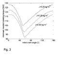
- Figure 3 depicts the torque needed to get through the first compression at a cold cranking temperature of -29°C for a typical engine in dependence on said initial cranking angle. Three different curves are shown corresponding to three different values J of the inertia moment of engine and starter. From Figure 3 it is evident that the torque required to get through the first compression has a minimum at a certain optimal crank angle (roughly between 45° to 80°). This is the result of a lower compression pressure in the first compressing cylinder.
- This lower pressure results in a lower compression torque and therefore the residual torque that the cranking aid has available (difference between what the cranking aid should deliver and the sum of friction and compression torque of engine) can be stored as kinetic energy in the lumped crankshaft inertia by accelerating it. This kinetic energy can be used in a later phase (i.e. during the maximum of the co m-pression torque) by extracting torque from the lumped crankshaft inertia through deceleration.
- Figures 4 and 5 show the effects of the initial crankshaft position on the maximum cylinder pressure and gas torque.
- Figure 4a to 4d show the relative cylinder pressure (vertical axis) of a 4 cylinder engine versus cranking angle (horizontal axis).
- the initial crank angle ⁇ 0 prior to cranking is -180° in Figure 4a, -135° in Figure 4b, -90° in Figure 4c, and -45° in Figure 4d whereby ⁇ 0 is 0° at TDC firing of cylinder 1.
- Comparison of the figures shows that the first peak of cylinder pressure is minimal at an initial cranking angle of -45°.
- Figures 5a and 5b are diagrams of the gas torque of a 4 cylinder engine during the first compressions (initial crank angle: -90°) showing the contribution of a first cylinder ( Figure 5a) and the complete engine ( Figure 5b).
- the optimal positioning of the initial crank angle does not only lower the torque needed to get through the first compression (improves cranking success) but also influences the time needed to crank the engine.
- the lower first compression peak namely results in a faster engine acceleration which has implication with for instance Stop-Start (hot cranking).
- Figures 6a to 6c depict three different types of starters for an internal combustion engine 1.
- Figure 6a shows an conventional starter motor 2a that is coupled to the crankshaft via a pinion 3 and a ring gear 5, the transmission ratio of ring gear to pinion being typically in the order of 14:1.
- a clutch/gearbox 4 is shown.
- Figure 6b shows an Integrated Starter-Generator (ISG) 2b that is coupled via a belt to the internal combustion engine 1, the pulley ratio of this coupling being about 3:1.
- a flywheel 5 and a clutch/gearbox 4 are shown.
- figure 6c depicts an ISG 2c that is integrated into the flywheel between internal combustion engine 1 and clutch/gearbox 4.
- the transmission ratio is 1:1 in this case.
- Figure 6c shows a crankshaft lock 6, too.
- a crankshaft lock has the advantage of maintaining a prepositioned optimal crankshaft starting angle or any crankshaft angle that has been determined and stored before the engine is shut down. Prepositioning is best done immediately before engine shutdown while it is still warm to minimize the required electrical energy. However, an angle near a torque peak is unstable, because the torque applied to the crankshaft by compressed gas may rotate the crankshaft out of the optimal position after the prepositioning is completed. Therefore, a mechanism is required that allows the crankshaft to be positioned by the starter and then to hold the preset angle against the forces of the compressed gasses.
- a freeway clutch which only allows rotation in one direction when it is engaged.
- crankshaft angle may still be changed if the vehicle is shoved while it is parked and in gear.
- the mechanism 6 of figure 6c that locks the rotation of the crankshaft in both directions would prevent this.
- crankshaft angle that a combustion engine arrives at when it is shut down without actively influencing it.
- the stored crankshaft angle could then be used to shorten starting times, because it would not be necessary to rotate the crankshaft several times in order to initiate the determination of crankshaft position.
- the engine must be rotated a minimum number of times before a determination is possible. If the crankshaft angle at engine shutdown is stored for use when restarting, the crankshaft should also be locked to prevent rotation in both directions.
- the locking mechanism 6 of figure 6c accomplishes this, too.
- a locking mechanism 6 that prevents rotation in two directions may be realized by pins or ratchets that engage with a gear on the crankshaft or by a friction belt.
- a starter-alternator 2b, 2c When starting a vehicle in cold weather, a starter-alternator 2b, 2c is at a disadvantage compared with a conventional starter 2a.
- a crankshaft mounted starter-alternator 2c there is no torque multiplying gear or pulley ratio between the electric machine and crankshaft, and in the case of a belt driven starter-alternator 2b, the maximum ratio is dictated by packaging constraints and inertial effects of the electric machine on the drive train during acceleration of the vehicle.
- a B-ISG 2b may have a maximum pulley ratio to the crankshaft of about 3:1, gear ratios of 14:1 are possible with a conventional starter motor 2a.
- the power rating and maximal torque of a starter-alternator must be large enough to overcome motoring torque peaks that are encountered when the combustion engine is cranked.
- the peaks are associated with a reciprocating component of the motoring torque that is dependent on the crankshaft angle.
- the total motoring torque including the absolute value of the peaks increases as the temperatures decrease, and the starter-alternator must be dimensioned to overcome them at the lowest defined ambient operating temperature in order to start the engine.
- a vehicle encounters these very low operating temperatures seldom.
- the motoring torque that a starter-alternator has to overcome is much lower than the extreme cold weather values.
- the electric machine is usually dimensioned at a much higher torque rating than is normally required. It is therefore desirable to lower the required torque during cold weather starting by maximizing the inertial energy stored in the rotating crankshaft and starter-alternator before the first compression is reached.
- a further advantage in prepositioning the crankshaft is a lowering of the amount of rotations needed to restart a combustion engine.
- a minimum number of rotations are necessary for the Engine Control Module to observe signals coming from the crankshaft position sensor in order to ascertain the correct position. If the absolute crank angle is known in advance when the engine is started, fuel delivery and ignition could be initiated without first rotating the crankshaft to determine crank angle.
Landscapes
- Engineering & Computer Science (AREA)
- Chemical & Material Sciences (AREA)
- Combustion & Propulsion (AREA)
- Mechanical Engineering (AREA)
- General Engineering & Computer Science (AREA)
- Combined Controls Of Internal Combustion Engines (AREA)
- Control Of Vehicle Engines Or Engines For Specific Uses (AREA)
- Output Control And Ontrol Of Special Type Engine (AREA)
Priority Applications (3)
| Application Number | Priority Date | Filing Date | Title |
|---|---|---|---|
| DE60238414T DE60238414D1 (de) | 2002-11-25 | 2002-11-25 | Verfahren und Vorrichtung zum Abstellen und Wiederanlassen einer Brennkraftmaschine |
| EP02102629A EP1422421B1 (fr) | 2002-11-25 | 2002-11-25 | Méthode et dispositif d'arrêt et de redémarrage d'un moteur à combustion interne |
| US10/720,620 US20040133333A1 (en) | 2002-11-25 | 2003-11-24 | Method and system for controlling shutdown and restart of an internal combustion engine |
Applications Claiming Priority (1)
| Application Number | Priority Date | Filing Date | Title |
|---|---|---|---|
| EP02102629A EP1422421B1 (fr) | 2002-11-25 | 2002-11-25 | Méthode et dispositif d'arrêt et de redémarrage d'un moteur à combustion interne |
Publications (3)
| Publication Number | Publication Date |
|---|---|
| EP1422421A2 true EP1422421A2 (fr) | 2004-05-26 |
| EP1422421A3 EP1422421A3 (fr) | 2005-09-28 |
| EP1422421B1 EP1422421B1 (fr) | 2010-11-24 |
Family
ID=32187255
Family Applications (1)
| Application Number | Title | Priority Date | Filing Date |
|---|---|---|---|
| EP02102629A Expired - Fee Related EP1422421B1 (fr) | 2002-11-25 | 2002-11-25 | Méthode et dispositif d'arrêt et de redémarrage d'un moteur à combustion interne |
Country Status (3)
| Country | Link |
|---|---|
| US (1) | US20040133333A1 (fr) |
| EP (1) | EP1422421B1 (fr) |
| DE (1) | DE60238414D1 (fr) |
Cited By (4)
| Publication number | Priority date | Publication date | Assignee | Title |
|---|---|---|---|---|
| EP1712765A1 (fr) * | 2005-04-07 | 2006-10-18 | Siemens Aktiengesellschaft | Procédé pour l'amélioration de la répétabilité du démarrage d'un moteur à combustion interne fonctionnant en mode start-stop |
| WO2009092466A1 (fr) * | 2008-01-22 | 2009-07-30 | Robert Bosch Gmbh | Procédé pour démarrer un moteur à combustion interne avec fonction d'arrêt et de redémarrage |
| EP3379060A3 (fr) * | 2017-03-14 | 2018-10-24 | Kwang Yang Motor Co., Ltd. | Système et procédé permettant à un contrôleur de générateur de démarreur intégré d'acquérir un degré d'angle de vilebrequin pour le vilebrequin d'un moteur |
| US10451018B2 (en) | 2013-11-26 | 2019-10-22 | Ford Global Technologies, Llc | Method of controlling a belt drive of an engine of a motor vehicle |
Families Citing this family (9)
| Publication number | Priority date | Publication date | Assignee | Title |
|---|---|---|---|---|
| JP5283786B2 (ja) * | 2010-09-16 | 2013-09-04 | 新電元工業株式会社 | 駆動制御装置、駆動制御システム、および、駆動制御方法 |
| DE102010050123A1 (de) * | 2010-11-03 | 2012-05-03 | Audi Ag | Kraftfahrzeug mit einem Hybridantrieb und Verfahren zur Auswahl einer Elektromaschine und/oder eines Anlassers zum Anlassen eines Verbrennungsmotors |
| JP5958416B2 (ja) * | 2013-05-08 | 2016-08-02 | マツダ株式会社 | 予混合圧縮着火式エンジンの始動制御装置 |
| US20140350826A1 (en) * | 2013-05-27 | 2014-11-27 | Kia Motors Corporation | Engine start control system for vehicle with isg and method thereof |
| DE102014217455B4 (de) * | 2014-09-02 | 2016-12-01 | Robert Bosch Gmbh | Verfahren zum Starten eines Verbrennungsmotors durch einen riemengetriebenen Startergenerator |
| WO2016136795A1 (fr) * | 2015-02-27 | 2016-09-01 | 株式会社デンソー | Dispositif de démarrage de moteur et procédé de démarrage de moteur |
| JP6547643B2 (ja) * | 2015-02-27 | 2019-07-24 | 株式会社デンソー | エンジン始動装置 |
| JP6153147B2 (ja) * | 2015-05-12 | 2017-06-28 | 三菱電機株式会社 | モータジェネレータ、エンジン始動装置、およびエンジン始動制御方法 |
| TWI561729B (en) * | 2015-10-29 | 2016-12-11 | Sanyang Motor Co Ltd | Method for controlling engines running |
Citations (1)
| Publication number | Priority date | Publication date | Assignee | Title |
|---|---|---|---|---|
| WO2001048373A1 (fr) | 1999-12-28 | 2001-07-05 | Robert Bosch Gmbh | Dispositif et procede pour arreter, de maniere controlee, un moteur a combustion interne |
Family Cites Families (8)
| Publication number | Priority date | Publication date | Assignee | Title |
|---|---|---|---|---|
| US5713320A (en) * | 1996-01-11 | 1998-02-03 | Gas Research Institute | Internal combustion engine starting apparatus and process |
| DE19817497A1 (de) * | 1998-04-20 | 1999-10-28 | Isad Electronic Sys Gmbh & Co | Verfahren und Startersystem zum Starten eines Verbrennungsmotors |
| JP3931450B2 (ja) * | 1998-10-09 | 2007-06-13 | トヨタ自動車株式会社 | ハイブリッド車両およびその制御方法 |
| DE19929393A1 (de) * | 1999-06-26 | 2000-12-28 | Schaeffler Waelzlager Ohg | Verfahren zur Ansteuerung einer Vorrichtung zum Variieren der Ventilsteuerzeiten einer Brennkraftmaschine, insbesondere einer Nockenwellen-Verstelleinrichtung mit hydraulisch entriegelbarer Startverriegelung |
| FR2806757B1 (fr) * | 2000-03-21 | 2002-06-21 | Peugeot Citroen Automobiles Sa | Procede et dispositif de positionnement d'un moteur thermique, dans une position d'arret facilitant le demarrage |
| DE10050170A1 (de) * | 2000-10-11 | 2002-04-25 | Daimler Chrysler Ag | Vorrichtung zum Starten einer Brennkraftmaschine |
| US6453864B1 (en) * | 2001-01-16 | 2002-09-24 | General Motors Corporation | Crankshaft rotation control in a hybrid electric vehicle |
| FR2824873B1 (fr) * | 2001-05-15 | 2003-09-19 | Peugeot Citroen Automobiles Sa | Dispositif et procede d'arret d'un moteur d'un vehicule automobile dans une position facilitant un redemarrage du moteur |
-
2002
- 2002-11-25 EP EP02102629A patent/EP1422421B1/fr not_active Expired - Fee Related
- 2002-11-25 DE DE60238414T patent/DE60238414D1/de not_active Expired - Lifetime
-
2003
- 2003-11-24 US US10/720,620 patent/US20040133333A1/en not_active Abandoned
Patent Citations (1)
| Publication number | Priority date | Publication date | Assignee | Title |
|---|---|---|---|---|
| WO2001048373A1 (fr) | 1999-12-28 | 2001-07-05 | Robert Bosch Gmbh | Dispositif et procede pour arreter, de maniere controlee, un moteur a combustion interne |
Cited By (7)
| Publication number | Priority date | Publication date | Assignee | Title |
|---|---|---|---|---|
| EP1712765A1 (fr) * | 2005-04-07 | 2006-10-18 | Siemens Aktiengesellschaft | Procédé pour l'amélioration de la répétabilité du démarrage d'un moteur à combustion interne fonctionnant en mode start-stop |
| WO2009092466A1 (fr) * | 2008-01-22 | 2009-07-30 | Robert Bosch Gmbh | Procédé pour démarrer un moteur à combustion interne avec fonction d'arrêt et de redémarrage |
| CN101925736B (zh) * | 2008-01-22 | 2013-09-25 | 罗伯特.博世有限公司 | 用于起动具有起动-停止功能的内燃机的方法 |
| US8904985B2 (en) | 2008-01-22 | 2014-12-09 | Robert Bosch Gmbh | Method for starting an internal combustion engine with start-stop function |
| US10451018B2 (en) | 2013-11-26 | 2019-10-22 | Ford Global Technologies, Llc | Method of controlling a belt drive of an engine of a motor vehicle |
| EP3379060A3 (fr) * | 2017-03-14 | 2018-10-24 | Kwang Yang Motor Co., Ltd. | Système et procédé permettant à un contrôleur de générateur de démarreur intégré d'acquérir un degré d'angle de vilebrequin pour le vilebrequin d'un moteur |
| TWI658200B (zh) * | 2017-03-14 | 2019-05-01 | 光陽工業股份有限公司 | 一體式啓動發電機的曲軸位置同步化控制方法及系統 |
Also Published As
| Publication number | Publication date |
|---|---|
| US20040133333A1 (en) | 2004-07-08 |
| EP1422421B1 (fr) | 2010-11-24 |
| EP1422421A3 (fr) | 2005-09-28 |
| DE60238414D1 (de) | 2011-01-05 |
Similar Documents
| Publication | Publication Date | Title |
|---|---|---|
| EP1422420B1 (fr) | Mécanisme de blocage pour le vilebrequin d'un moteur à combustion interne | |
| EP1422421B1 (fr) | Méthode et dispositif d'arrêt et de redémarrage d'un moteur à combustion interne | |
| JP3941441B2 (ja) | 内燃機関の始動時制御装置 | |
| US7331320B2 (en) | Engine starting apparatus and method | |
| US8826878B2 (en) | Multiple gear ratio starter motor | |
| US5323743A (en) | Sure-start device for internal combustion engines | |
| US6781252B2 (en) | Method and apparatus for starting an engine using a starter/alternator and an accessory drive | |
| JP2002512342A (ja) | 内燃機関を始動させる方法およびスタータ・システム | |
| US20050252474A1 (en) | Multi-stage compression ignition engine start | |
| JP2001503831A (ja) | 内燃機関のためのスタータユニット | |
| USRE38671E1 (en) | Method and apparatus for starting an engine having a turbocharger | |
| US20090024287A1 (en) | Internal combustion engine | |
| GB2489499A (en) | A method and system for controlling restart of an engine | |
| US10570870B2 (en) | Hybrid module, hybrid unit and motor vehicle as well as starting process for an internal combustion engine | |
| US20150059688A1 (en) | Control apparatus and control method for internal combustion engine | |
| JP2002364500A (ja) | 内燃機関の始動制御装置 | |
| CN107795423B (zh) | 发动机起动系统 | |
| US20030102173A1 (en) | Drivetrain for a motor vehicle | |
| US6286470B1 (en) | Starting process for an internal-combustion engine | |
| JP2004100616A (ja) | 内燃機関の始動制御装置 | |
| KR100759059B1 (ko) | 내연기관을 시동하도록 작동되는 전기기계를 제어하는제어장치 | |
| JP4207048B2 (ja) | 内燃機関の始動時制御装置 | |
| JP2001280185A (ja) | 内燃機関の始動制御装置およびこれを備える車両 | |
| JP2001304005A (ja) | 内燃機関の自動運転停止制御 | |
| EP1106824A1 (fr) | Méthode et dispositif de démarrage d'un moteur à combustion interne muni d'un démarreur s'adaptant au couple d'entraínement du moteur |
Legal Events
| Date | Code | Title | Description |
|---|---|---|---|
| PUAI | Public reference made under article 153(3) epc to a published international application that has entered the european phase |
Free format text: ORIGINAL CODE: 0009012 |
|
| AK | Designated contracting states |
Kind code of ref document: A2 Designated state(s): AT BE BG CH CY CZ DE DK EE ES FI FR GB GR IE IT LI LU MC NL PT SE SK TR |
|
| AX | Request for extension of the european patent |
Extension state: AL LT LV MK RO SI |
|
| PUAL | Search report despatched |
Free format text: ORIGINAL CODE: 0009013 |
|
| AK | Designated contracting states |
Kind code of ref document: A3 Designated state(s): AT BE BG CH CY CZ DE DK EE ES FI FR GB GR IE IT LI LU MC NL PT SE SK TR |
|
| AX | Request for extension of the european patent |
Extension state: AL LT LV MK RO SI |
|
| 17P | Request for examination filed |
Effective date: 20060328 |
|
| RAP1 | Party data changed (applicant data changed or rights of an application transferred) |
Owner name: FORD GLOBAL TECHNOLOGIES, LLC |
|
| AKX | Designation fees paid |
Designated state(s): DE FR GB |
|
| 17Q | First examination report despatched |
Effective date: 20060719 |
|
| GRAP | Despatch of communication of intention to grant a patent |
Free format text: ORIGINAL CODE: EPIDOSNIGR1 |
|
| GRAS | Grant fee paid |
Free format text: ORIGINAL CODE: EPIDOSNIGR3 |
|
| GRAA | (expected) grant |
Free format text: ORIGINAL CODE: 0009210 |
|
| RAP1 | Party data changed (applicant data changed or rights of an application transferred) |
Owner name: FORD GLOBAL TECHNOLOGIES, LLC |
|
| AK | Designated contracting states |
Kind code of ref document: B1 Designated state(s): DE FR GB |
|
| REG | Reference to a national code |
Ref country code: GB Ref legal event code: FG4D |
|
| REF | Corresponds to: |
Ref document number: 60238414 Country of ref document: DE Date of ref document: 20110105 Kind code of ref document: P |
|
| PLBE | No opposition filed within time limit |
Free format text: ORIGINAL CODE: 0009261 |
|
| STAA | Information on the status of an ep patent application or granted ep patent |
Free format text: STATUS: NO OPPOSITION FILED WITHIN TIME LIMIT |
|
| 26N | No opposition filed |
Effective date: 20110825 |
|
| REG | Reference to a national code |
Ref country code: DE Ref legal event code: R097 Ref document number: 60238414 Country of ref document: DE Effective date: 20110825 |
|
| REG | Reference to a national code |
Ref country code: FR Ref legal event code: PLFP Year of fee payment: 14 |
|
| REG | Reference to a national code |
Ref country code: FR Ref legal event code: PLFP Year of fee payment: 15 |
|
| REG | Reference to a national code |
Ref country code: FR Ref legal event code: PLFP Year of fee payment: 16 |
|
| REG | Reference to a national code |
Ref country code: FR Ref legal event code: PLFP Year of fee payment: 17 |
|
| PGFP | Annual fee paid to national office [announced via postgrant information from national office to epo] |
Ref country code: DE Payment date: 20181015 Year of fee payment: 17 |
|
| PGFP | Annual fee paid to national office [announced via postgrant information from national office to epo] |
Ref country code: GB Payment date: 20181025 Year of fee payment: 17 Ref country code: FR Payment date: 20181017 Year of fee payment: 17 |
|
| REG | Reference to a national code |
Ref country code: DE Ref legal event code: R119 Ref document number: 60238414 Country of ref document: DE |
|
| GBPC | Gb: european patent ceased through non-payment of renewal fee |
Effective date: 20191125 |
|
| PG25 | Lapsed in a contracting state [announced via postgrant information from national office to epo] |
Ref country code: GB Free format text: LAPSE BECAUSE OF NON-PAYMENT OF DUE FEES Effective date: 20191125 Ref country code: FR Free format text: LAPSE BECAUSE OF NON-PAYMENT OF DUE FEES Effective date: 20191130 Ref country code: DE Free format text: LAPSE BECAUSE OF NON-PAYMENT OF DUE FEES Effective date: 20200603 |