EP1421415B1 - Anordnung und vorrichtung zur optischen strahlhomogenisierung - Google Patents
Anordnung und vorrichtung zur optischen strahlhomogenisierung Download PDFInfo
- Publication number
- EP1421415B1 EP1421415B1 EP02748729A EP02748729A EP1421415B1 EP 1421415 B1 EP1421415 B1 EP 1421415B1 EP 02748729 A EP02748729 A EP 02748729A EP 02748729 A EP02748729 A EP 02748729A EP 1421415 B1 EP1421415 B1 EP 1421415B1
- Authority
- EP
- European Patent Office
- Prior art keywords
- sections
- convex
- exit surface
- concave
- curvature
- Prior art date
- Legal status (The legal status is an assumption and is not a legal conclusion. Google has not performed a legal analysis and makes no representation as to the accuracy of the status listed.)
- Expired - Lifetime
Links
- 238000000265 homogenisation Methods 0.000 title claims abstract description 24
- 230000003287 optical effect Effects 0.000 title claims abstract description 15
- 230000007704 transition Effects 0.000 claims abstract description 16
- 238000011144 upstream manufacturing Methods 0.000 claims 1
- 238000009826 distribution Methods 0.000 description 11
- 239000007787 solid Substances 0.000 description 9
- 238000010586 diagram Methods 0.000 description 4
- 230000015572 biosynthetic process Effects 0.000 description 2
- 238000005755 formation reaction Methods 0.000 description 2
- 239000000758 substrate Substances 0.000 description 2
- 238000012935 Averaging Methods 0.000 description 1
- 230000006835 compression Effects 0.000 description 1
- 238000007906 compression Methods 0.000 description 1
- 238000000034 method Methods 0.000 description 1
- 239000011295 pitch Substances 0.000 description 1
- 230000003746 surface roughness Effects 0.000 description 1
Images

Classifications
-
- G—PHYSICS
- G02—OPTICS
- G02B—OPTICAL ELEMENTS, SYSTEMS OR APPARATUS
- G02B3/00—Simple or compound lenses
- G02B3/02—Simple or compound lenses with non-spherical faces
- G02B3/08—Simple or compound lenses with non-spherical faces with discontinuous faces, e.g. Fresnel lens
-
- G—PHYSICS
- G02—OPTICS
- G02B—OPTICAL ELEMENTS, SYSTEMS OR APPARATUS
- G02B19/00—Condensers, e.g. light collectors or similar non-imaging optics
- G02B19/0033—Condensers, e.g. light collectors or similar non-imaging optics characterised by the use
- G02B19/0047—Condensers, e.g. light collectors or similar non-imaging optics characterised by the use for use with a light source
- G02B19/0052—Condensers, e.g. light collectors or similar non-imaging optics characterised by the use for use with a light source the light source comprising a laser diode
- G02B19/0057—Condensers, e.g. light collectors or similar non-imaging optics characterised by the use for use with a light source the light source comprising a laser diode in the form of a laser diode array, e.g. laser diode bar
-
- G—PHYSICS
- G02—OPTICS
- G02B—OPTICAL ELEMENTS, SYSTEMS OR APPARATUS
- G02B19/00—Condensers, e.g. light collectors or similar non-imaging optics
- G02B19/0004—Condensers, e.g. light collectors or similar non-imaging optics characterised by the optical means employed
- G02B19/0009—Condensers, e.g. light collectors or similar non-imaging optics characterised by the optical means employed having refractive surfaces only
- G02B19/0014—Condensers, e.g. light collectors or similar non-imaging optics characterised by the optical means employed having refractive surfaces only at least one surface having optical power
-
- G—PHYSICS
- G02—OPTICS
- G02B—OPTICAL ELEMENTS, SYSTEMS OR APPARATUS
- G02B19/00—Condensers, e.g. light collectors or similar non-imaging optics
- G02B19/0033—Condensers, e.g. light collectors or similar non-imaging optics characterised by the use
- G02B19/0095—Condensers, e.g. light collectors or similar non-imaging optics characterised by the use for use with ultraviolet radiation
-
- G—PHYSICS
- G02—OPTICS
- G02B—OPTICAL ELEMENTS, SYSTEMS OR APPARATUS
- G02B27/00—Optical systems or apparatus not provided for by any of the groups G02B1/00 - G02B26/00, G02B30/00
- G02B27/09—Beam shaping, e.g. changing the cross-sectional area, not otherwise provided for
-
- G—PHYSICS
- G02—OPTICS
- G02B—OPTICAL ELEMENTS, SYSTEMS OR APPARATUS
- G02B27/00—Optical systems or apparatus not provided for by any of the groups G02B1/00 - G02B26/00, G02B30/00
- G02B27/09—Beam shaping, e.g. changing the cross-sectional area, not otherwise provided for
- G02B27/0927—Systems for changing the beam intensity distribution, e.g. Gaussian to top-hat
-
- G—PHYSICS
- G02—OPTICS
- G02B—OPTICAL ELEMENTS, SYSTEMS OR APPARATUS
- G02B27/00—Optical systems or apparatus not provided for by any of the groups G02B1/00 - G02B26/00, G02B30/00
- G02B27/09—Beam shaping, e.g. changing the cross-sectional area, not otherwise provided for
- G02B27/0938—Using specific optical elements
- G02B27/095—Refractive optical elements
- G02B27/0955—Lenses
- G02B27/0966—Cylindrical lenses
-
- G—PHYSICS
- G02—OPTICS
- G02B—OPTICAL ELEMENTS, SYSTEMS OR APPARATUS
- G02B27/00—Optical systems or apparatus not provided for by any of the groups G02B1/00 - G02B26/00, G02B30/00
- G02B27/09—Beam shaping, e.g. changing the cross-sectional area, not otherwise provided for
- G02B27/0938—Using specific optical elements
- G02B27/0977—Reflective elements
Definitions
- the present invention relates to an apparatus for optical beam homogenization according to the preamble of claim 1. Furthermore, the present invention relates to an arrangement for optical beam homogenization according to the preamble of claim 5.
- a device of the aforementioned type is known from JP 2000 111714 A known.
- a cylindrical lens array with alternating convex and concave cylindrical lenses is provided on the entrance side of a transparent substrate.
- a cylindrical lens array with alternating convex and concave cylindrical lenses is also provided on the exit side of the transparent substrate.
- the cylinder axes of the cylindrical lenses are arranged on the entry side perpendicular to the cylinder axes of the cylindrical lenses on the exit side.
- the cylindrical lenses can each have a sinusoidal cross-section.
- a first cylindrical lens array with alternately convex and concave cylindrical lenses and a second cylindrical lens array with alternating convex and concave cylindrical lenses are provided in the propagation direction of the beam to be homogenized in succession.
- the cylinder axes of the cylindrical lenses of the first array are arranged perpendicular to the cylinder axes of the cylindrical lenses of the second array.
- the cylindrical lenses can each have a part-circular or a parabolic Have cross-section.
- a converging lens is arranged behind the device, which focuses the light beam in such a way that it is more homogeneous approximately in the region of the focal plane of the condenser lens than before entry into the device.
- a further apparatus for optical beam homogenization and a further arrangement for optical beam homogenization are known from PCT application WO 98/10317 known.
- the device described therein comprises both on its entrance surface and on its exit surface a whole series of parallel and juxtaposed cylindrical lenses.
- the cylindrical lenses of the entrance surface and the cylindrical lenses of the exit surface are arranged perpendicular to each other with respect to their cylinder axis.
- Behind the device a converging lens is arranged, which can focus the light passing through the device to a focal plane.
- homogenization can be achieved by deflecting partial beams of the light beam incident on different areas of the cylindrical lenses into different solid angle elements. The light beam is thus slightly more divergent after passing through the optical beam homogenizing device than before entry.
- these incident partial beams are deflected in parallel in such a way that they are brought together in one focal point in the focal plane. It thus takes place in the focal plane, a superposition of individual partial beams, with a uniform scattering was achieved in different solid angle ranges by the previous refraction of the cylindrical lenses. For this reason, the cross section of the light beam in the focal plane is comparatively homogeneous.
- a disadvantage of the aforementioned device and the aforementioned arrangement proves that the device is composed of adjacent convex cylindrical lenses, wherein in the Connection region of these cylindrical lenses an extremely strong curvature of the surface of the entrance surface or the exit surface is present.
- the partial beams of the light beam to be homogenized which impinge into these connecting regions either pass unhindered through these connecting regions, so that they can not be homogenized. Alternatively, they are deflected uncontrollably in different directions, so that they emerge from the beam and thus are to be regarded as losses. Furthermore, there is the danger that such a small radius of curvature is present in these sharp-edged connection areas that unwanted high-intensity focus formations occur within the device or shortly behind the device. This can lead to damage at correspondingly high laser intensities. As a further disadvantage, it can also prove at very high laser intensities that they are convex cylindrical lenses which form focal lines of high intensity behind the device for optical beam homogenization, so that damage to the surroundings can also occur in these focus areas.
- the problem underlying the present invention is to provide a device and an arrangement of the type mentioned, which are designed more effective.
- the convex portions and the concave portions in the direction perpendicular to the direction of constant curvature each have an elliptical or a hyperbolic shape.
- the transition between these sections can be made relatively smooth, ie without additional steps or edges.
- the curvature of the convex portion may transition to the curvature of the concave portion.
- relatively smooth may mean that the transition region between the convex portions and the concave portions is smooth in comparison with the spatial extent of the convex and concave portions in a direction perpendicular to the entrance surface and the exit surface, in particular has no step or edge which in terms of their Expansion with the extension of the sections in a direction perpendicular to the entrance surface and the exit surface direction is comparable.
- transition region between the convex and the concave sections should have no surface roughness. Rather, the transition area between these sections have no steps or edges, which are substantially smaller in terms of their spatial extent than the spatial extent of the convex and concave portions in the light passing direction.
- This smooth design of the transition between the convex portions and the concave portions ensures that light passing through this transition region is not scattered uncontrollably out of the device. In this way, the effectiveness is increased, in particular with regard to the luminous efficacy. Furthermore, this smooth transition also produces no sharp curves that could lead to high-intensity focus points or focus lines behind the device. Furthermore, even through this seamless connection region between the convex and concave sections, no light rays impinging on this region can pass unhindered. Thus, in principle, each of the partial beams impinging on the device is deflected so that optimum homogenization of the light beam entering the device can be ensured.
- the convex portions and the concave portions have a respective direction lying in the entrance surface and the exit surface along which at least partially the curvature of the sections is substantially constant, the direction of substantially constant curvature of the entrance surface to the direction substantially constant curvature of the exit surface is oriented vertically.
- a convex elongated lens-like structure is always adjacent to a concave lens-like elongated structure. In this way, in contrast to the state of the Technique of smooth transition without steps or edges between the convex and concave sections or lens-like structures can be ensured.
- the convex portions and the concave portions have either an elliptical shape or a hyperbolic shape in the direction perpendicular to the direction of constant curvature.
- Such surface configurations of the convex and concave sections avoid the formation of high-intensity focus areas behind the optical beam homogenization device.
- elliptical lenses for example, do not have a sharply defined focus area because they have a substantially constantly changing curvature perpendicular to the direction of constant curvature.
- the convex and concave sections configured as elliptical or hyperbolic shapes additionally have the advantage that they can be designed in such a way that a highly effective homogenization of the beam cross section can take place. This is described in the following description of the figures with reference to FIG. 4 even more clearly explained.
- the curvature of the convex portions is formed on the average weaker than the curvature of the concave portions. In this way, the light intensity in the focus areas behind the convex portions is further reduced. Behind the concave sections, there are no focus areas due to the fact that they act as diverging lenses.
- convex portions and concave portions are formed both on the entrance surface and on the exit surface, preferably about 100 to 500, in particular about 300.
- this number of convex and concave adjacent sections be increased or reduced. This depends inter alia on the quality of the intensity distribution of the cross section of the incident light beam.
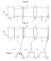
- Pictured inventive arrangement comprises a light source 1 with a light beam 2 emanating from this light source, which by a device according to the invention 3 for beam homogenization passes and is then focused by a converging lens 4.
- the emerging from the converging lens 4 light beam 5 is in Fig. 1a and Fig. 1b in its course up to the focal plane 6 of the converging lens 4 shown.
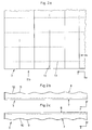
- Fig. 2 the device 3 according to the invention for beam homogenization is shown in detail.
- the structure of the device 3 is not to scale but exaggerated for clarity.
- the device 3 has a substantially square inlet surface 7 and a substantially square outlet surface 8 opposite this.
- convex portions 9, 11 and concave portions 10, 12 are formed on the entry surface 7 and exit surface 8 convex portions 9, 11 and concave portions 10, 12 are formed.
- Fig. 2b the convex portions 11 and the concave portions 12 of the exit surface 8 can be seen in section.
- Both the convex portions 11 and the concave portions 12 extend in one direction, namely in the x-direction with an invariable cross section, so that the Fig.
- Z '(y 1 ) Z' (y 2 ) for infinitesimally adjacent points y 1 , y 2 in the transition region between the convex portions 9, 11 and the concave portions 10, 12.
- Z '(y) is the first derivative of the function Z (y).
- the convex portions 9, 11 may for example have a width of about 30 microns.
- the concave portions 10, 12 may have a width of 70 microns.
- the depth, ie the extension in the z-direction, of the convex sections 9, 11 from the transition region to the vertex may be less than 1 ⁇ m, for example between 0.2 and 0.3 ⁇ m.
- the depth of the concave sections 10, 12 in the z-direction may also be less than 1 ⁇ m, for example 0.8 ⁇ m.
- the device 3 it is entirely conceivable to choose other dimensions for the device 3 according to the invention. However, it is completely sufficient to select the aforementioned very shallow depths of less than 1 ⁇ m for the convex sections 9, 11 and the concave sections 10, 12. Furthermore, in some applications there is no need to choose such a small period wave length of the succession of convex and concave sections 9, 10, 11, 12. In the present case, the period wavelength between two apex lines 13 of the convex portions 9, 11 is about 100 microns. With corresponding applications, it is certainly possible to select period wavelengths between the crest lines 13 in the millimeter range.
- Fig. 3 shows in detail how uniformly incident on, for example, the interface 8 partial beams of the light beam 2 are deflected differently. It can be clearly seen that the partial beams passing through the concave portions 12 are scattered away from each other, so that no focusing takes place in the z direction behind the concave portions 12.
- the concave portions 12 act like a diverging lens.
- partial beams passing through the convex portions 11 are brought closer to each other in a focus area 14.
- the convex portions 11 act in this case similar to a converging lens. However, this focus area 14 does not represent a spatially very concentrated focus point. Rather, in the illustrated embodiment, compression of the partial beams incident on the convex sections 11 takes place by a factor of about 6.
- the focus area 14 in the x direction have an extension of about 5 microns.
- This comparatively smeared focus area 14 results from the fact that the convex portion in contrast to spherical geometry, as is the case with regular cylindrical lenses, no constant curvature but just a substantially constantly changing curvature due to the elliptical cross-section has.
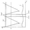
- Fig. 4 the relationship between the partial beams incident in certain spatial regions x, y and the solid angles ⁇ is shown.
- a part of the exit surface 8 indicated schematically.
- the following considerations apply analogously to the entry surface 7 it can be seen that sub-beams deflected into a solid angle element ⁇ each contain contributions from adjacent spatial regions ⁇ x 1 , y 1 or ⁇ x 2 , y 2 .
- These space regions ⁇ x 1 , y 1 and ⁇ x 2 , y 2 are as shown Fig. 4 can be seen in adjacent concave or convex portions of the exit surface 8 arranged. Furthermore, it is off Fig.
- Fig. 1c clarified.
- the intensity distribution I (x, y) of the light beam 2 is shown before entering the device 3 according to the invention.
- Fig. 1c can be taken that the intensity is very inhomogeneous distributed over the cross-sectional area of the light beam 2. Such an extremely inhomogeneous intensity distribution is typical for an excimer laser, for example.
- the middle of the three diagrams in Fig. 1c illustrates that the intensity distribution I ( ⁇ ) after passing through the device 3 according to the invention is very homogeneous, that is, in the same solid angle elements ⁇ essentially the same intensity is radiated.
- 1c illustrates that can be achieved by the converging lens 4 that in the focal plane 6 of the converging lens 4, the intensity distribution I (x, y) of the light beam 5 can be homogenized also in terms of spatial distribution.
- the reason for this is that light rays incident on a converging lens are focused in the focal plane 6 in one point, so that from a homogeneous intensity distribution I ( ⁇ ) with respect to the solid angles becomes a homogeneous intensity distribution I (x, y) with respect to the spatial distribution ,
- the focus regions 14 of the partial beams refracted by the convex portions 9 of the entrance surface 7 and the partial beams refracted by the convex portions 11 of the exit surface 8 will not overlap one another , Rather, these will be spaced apart in the z-direction accordingly. Thus, no areas of high intensity will be formed here. Of course, the same is achieved by selecting surfaces with an ellipse-like cross-section, as explained above.
Landscapes
- Physics & Mathematics (AREA)
- General Physics & Mathematics (AREA)
- Optics & Photonics (AREA)
- Lenses (AREA)
- Optical Elements Other Than Lenses (AREA)
- Physical Or Chemical Processes And Apparatus (AREA)
- Recrystallisation Techniques (AREA)
- Air Bags (AREA)
- Spectrometry And Color Measurement (AREA)
- Laser Beam Processing (AREA)
Applications Claiming Priority (3)
| Application Number | Priority Date | Filing Date | Title |
|---|---|---|---|
| DE10139355A DE10139355A1 (de) | 2001-08-17 | 2001-08-17 | Anordnung und Vorrichtung zur optischen Strahlhomogenisierung |
| DE10139355 | 2001-08-17 | ||
| PCT/EP2002/006042 WO2003016963A2 (de) | 2001-08-17 | 2002-06-03 | Anordnung und vorrichtung zur optischen strahlhomogenisierung |
Publications (2)
| Publication Number | Publication Date |
|---|---|
| EP1421415A2 EP1421415A2 (de) | 2004-05-26 |
| EP1421415B1 true EP1421415B1 (de) | 2012-03-14 |
Family
ID=7695049
Family Applications (1)
| Application Number | Title | Priority Date | Filing Date |
|---|---|---|---|
| EP02748729A Expired - Lifetime EP1421415B1 (de) | 2001-08-17 | 2002-06-03 | Anordnung und vorrichtung zur optischen strahlhomogenisierung |
Country Status (9)
| Country | Link |
|---|---|
| US (1) | US20040223225A1 (enExample) |
| EP (1) | EP1421415B1 (enExample) |
| JP (1) | JP2004521398A (enExample) |
| KR (1) | KR20040032928A (enExample) |
| CN (1) | CN100414322C (enExample) |
| AT (1) | ATE549655T1 (enExample) |
| AU (1) | AU2002319192A1 (enExample) |
| DE (1) | DE10139355A1 (enExample) |
| WO (1) | WO2003016963A2 (enExample) |
Families Citing this family (16)
| Publication number | Priority date | Publication date | Assignee | Title |
|---|---|---|---|---|
| DE10327733C5 (de) * | 2003-06-18 | 2012-04-19 | Limo Patentverwaltung Gmbh & Co. Kg | Vorrichtung zur Formung eines Lichtstrahls |
| DE102004020250A1 (de) * | 2004-04-26 | 2005-11-10 | Hentze-Lissotschenko Patentverwaltungs Gmbh & Co. Kg | Vorrichtung und Verfahren zur optischen Strahlhomogenisierung |
| JP4579575B2 (ja) | 2004-05-14 | 2010-11-10 | 株式会社半導体エネルギー研究所 | レーザ照射方法及びレーザ照射装置 |
| JP3963275B2 (ja) * | 2004-07-16 | 2007-08-22 | 株式会社エンプラス | 面光源装置、照明ユニット及び光束制御部材 |
| DE102004039936A1 (de) * | 2004-08-17 | 2006-02-23 | Hentze-Lissotschenko Patentverwaltungs Gmbh & Co. Kg | Vorrichtung zur Homogenisierung von Licht sowie Verfahren zur Herstellung der Vorrichtung |
| US7400456B2 (en) | 2004-09-21 | 2008-07-15 | Avago Technologies Ecbu Ip Pte Ltd | Lens having seamless profile defined by cubic polynomial function |
| KR101098338B1 (ko) | 2005-04-22 | 2011-12-26 | 삼성전자주식회사 | 광학 패키지, 광학 렌즈 및 이를 갖는 백라이트 어셈블리및 표시장치 |
| WO2007038954A1 (de) * | 2005-09-30 | 2007-04-12 | Limo Patentverwaltung Gmbh & Co. Kg | Vorrichtung zur homogenisierung von licht |
| WO2007048622A1 (de) * | 2005-10-27 | 2007-05-03 | Limo Patentverwaltung Gmbh & Co. Kg. | Vorrichtung zur homogenisierung von licht |
| US7907341B2 (en) * | 2006-09-28 | 2011-03-15 | Sumitomo Electric Industries, Ltd. | Laser processing method and laser processing apparatus |
| DE102008017947A1 (de) | 2008-04-09 | 2009-10-15 | Limo Patentverwaltung Gmbh & Co. Kg | Vorrichtung, Anordnung und Verfahren zur Homogenisierung zumindest teilweise kohärenten Laserlichts |
| DE102008024697B4 (de) | 2008-05-21 | 2014-02-27 | Limo Patentverwaltung Gmbh & Co. Kg | Vorrichtung zur Homogenisierung zumindest teilweise kohärenten Laserlichts |
| DE102008027231B4 (de) * | 2008-06-06 | 2016-03-03 | Limo Patentverwaltung Gmbh & Co. Kg | Vorrichtung zur Strahlformung |
| DE102009010693A1 (de) | 2009-02-26 | 2010-09-02 | Limo Patentverwaltung Gmbh & Co. Kg | Vorrichtung zur Homogenisierung von Laserstrahlung |
| US9046500B2 (en) * | 2012-12-20 | 2015-06-02 | Kla-Tencor Corporation | Adaptable illuminating apparatus, system, and method for extreme ultra-violet light |
| NL2017493B1 (en) * | 2016-09-19 | 2018-03-27 | Kulicke & Soffa Liteq B V | Optical beam homogenizer based on a lens array |
Family Cites Families (11)
| Publication number | Priority date | Publication date | Assignee | Title |
|---|---|---|---|---|
| US3476463A (en) * | 1965-05-11 | 1969-11-04 | Perkin Elmer Corp | Coherent light optical system yielding an output beam of desired intensity distribution at a desired equiphase surface |
| JPS49114434A (enExample) * | 1973-02-12 | 1974-10-31 | ||
| US4560259A (en) * | 1980-10-31 | 1985-12-24 | Humphrey Instruments, Inc. | Objective refractor for the eye |
| AU553164B2 (en) * | 1980-10-31 | 1986-07-03 | Allergan Humphrey | Objective refractor for the eye |
| US4605282A (en) * | 1983-12-22 | 1986-08-12 | Pyramid Optical, Inc. | Line lens and method of design therefor |
| US5400114A (en) * | 1991-09-05 | 1995-03-21 | Hitachi, Ltd. | Rear-projection screen and a rear projection image display employing the rear-projection screen |
| DE19635942A1 (de) * | 1996-09-05 | 1998-03-12 | Vitaly Dr Lissotschenko | Optisches Strahlformungssystem |
| US6115181A (en) * | 1996-11-22 | 2000-09-05 | 3M Innovative Properties Company | Variable beam splitter having opposed alternating convex and concave lens structures |
| JPH10253916A (ja) * | 1997-03-10 | 1998-09-25 | Semiconductor Energy Lab Co Ltd | レーザー光学装置 |
| JP2000111714A (ja) * | 1998-09-30 | 2000-04-21 | Konica Corp | ソフトフォーカスフィルタおよびソフトフォーカスフィルタユニット |
| JP2000321404A (ja) * | 1999-05-12 | 2000-11-24 | Keiwa Inc | 光拡散シート |
-
2001
- 2001-08-17 DE DE10139355A patent/DE10139355A1/de not_active Withdrawn
-
2002
- 2002-06-03 EP EP02748729A patent/EP1421415B1/de not_active Expired - Lifetime
- 2002-06-03 US US10/275,157 patent/US20040223225A1/en not_active Abandoned
- 2002-06-03 KR KR10-2004-7002338A patent/KR20040032928A/ko not_active Ceased
- 2002-06-03 AT AT02748729T patent/ATE549655T1/de active
- 2002-06-03 JP JP2003521410A patent/JP2004521398A/ja active Pending
- 2002-06-03 AU AU2002319192A patent/AU2002319192A1/en not_active Abandoned
- 2002-06-03 CN CNB028161394A patent/CN100414322C/zh not_active Expired - Fee Related
- 2002-06-03 WO PCT/EP2002/006042 patent/WO2003016963A2/de not_active Ceased
Also Published As
| Publication number | Publication date |
|---|---|
| AU2002319192A1 (en) | 2003-03-03 |
| KR20040032928A (ko) | 2004-04-17 |
| EP1421415A2 (de) | 2004-05-26 |
| WO2003016963A3 (de) | 2003-10-23 |
| ATE549655T1 (de) | 2012-03-15 |
| US20040223225A1 (en) | 2004-11-11 |
| WO2003016963A2 (de) | 2003-02-27 |
| CN100414322C (zh) | 2008-08-27 |
| CN1543578A (zh) | 2004-11-03 |
| JP2004521398A (ja) | 2004-07-15 |
| DE10139355A1 (de) | 2003-02-27 |
Similar Documents
| Publication | Publication Date | Title |
|---|---|---|
| EP1421415B1 (de) | Anordnung und vorrichtung zur optischen strahlhomogenisierung | |
| DE10327733B3 (de) | Vorrichtung zur Formung eines Lichtstrahls | |
| DE102006047941B4 (de) | Vorrichtung zur Homogenisierung von Strahlung mit nicht regelmäßigen Mikrolinsenarrays | |
| EP1839083B1 (de) | Vorrichtung zur homogenisierung von licht | |
| DE2709091C2 (enExample) | ||
| EP1006382A1 (de) | Anordnung und Vorrichtung zur optischen Strahltransformation | |
| DE102010053781B4 (de) | Vorrichtung zur Umwandlung von Laserstrahlung in Laserstrahlung mit einem M-Profil | |
| EP2217961A1 (de) | Vorrichtung zur strahlformung | |
| DE102004020250A1 (de) | Vorrichtung und Verfahren zur optischen Strahlhomogenisierung | |
| EP1934647A1 (de) | Vorrichtung zur homogenisierung von licht | |
| DE102007061358B4 (de) | Vorrichtung zur Formung von Laserstrahlung | |
| EP1062540B1 (de) | Vorrichtung und verfahren zur optischen strahltransformation | |
| WO2011012503A1 (de) | Optisches system zum erzeugen eines lichtstrahls zur behandlung eines substrats | |
| EP1062538B1 (de) | Ablenkvorrichtung für elektromagnetische strahlen oder strahlbündel im optischen spektralbereich | |
| EP2976672B1 (de) | Vorrichtung zur homogenisierung eines laserstrahls | |
| WO2008087012A1 (de) | Vorrichtung zur homogenisierung von licht sowie vorrichtung zur erzeugung einer linienförmigen intensitätsverteilung in einer arbeitsebene | |
| EP2389607B1 (de) | Vorrichtung zur strahlformung von laserdiodenarrays | |
| EP1943557B1 (de) | Vorrichtung zur homogenisierung von licht | |
| DE19820154A1 (de) | Vorrichtung und Verfahren zur optischen Strahltransformation | |
| DE102008017947A1 (de) | Vorrichtung, Anordnung und Verfahren zur Homogenisierung zumindest teilweise kohärenten Laserlichts | |
| DE102008056315A1 (de) | Vorrichtung zur Homogenisierung von Laserstrahlung sowie Vorrichtung zur Formung von Laserstrahlung | |
| DE10336957A1 (de) | Vorrichtung zur Formung eines Lichtstrahles | |
| DE19724061C2 (de) | Vorrichtung zur Laserbearbeitung eines Werkstückes | |
| DE102010012459A1 (de) | Vorrichtung zur Beaufschlagung eines zumindest teilweise reflektierenden oder transparenten Bereichs eines in einem Arbeitsbereich angeordneten Werkstücks mit Laserstrahlung | |
| DE10148170A1 (de) | Verfahren und Vorrichtung zur Verminderung von Speckle in einem optischen System |
Legal Events
| Date | Code | Title | Description |
|---|---|---|---|
| PUAI | Public reference made under article 153(3) epc to a published international application that has entered the european phase |
Free format text: ORIGINAL CODE: 0009012 |
|
| AK | Designated contracting states |
Kind code of ref document: A2 Designated state(s): AT BE CH CY DE DK ES FI FR GB GR IE IT LI LU MC NL PT SE TR |
|
| AX | Request for extension of the european patent |
Extension state: AL LT LV MK RO SI |
|
| 17P | Request for examination filed |
Effective date: 20040423 |
|
| RAP1 | Party data changed (applicant data changed or rights of an application transferred) |
Owner name: LIMO PATENTVERWALTUNG GMBH & CO. KG |
|
| 17Q | First examination report despatched |
Effective date: 20090930 |
|
| REG | Reference to a national code |
Ref country code: DE Ref legal event code: R079 Ref document number: 50215414 Country of ref document: DE Free format text: PREVIOUS MAIN CLASS: G02B0003080000 Ipc: G02B0027090000 |
|
| GRAP | Despatch of communication of intention to grant a patent |
Free format text: ORIGINAL CODE: EPIDOSNIGR1 |
|
| RIC1 | Information provided on ipc code assigned before grant |
Ipc: G02B 27/09 20060101AFI20110920BHEP |
|
| GRAS | Grant fee paid |
Free format text: ORIGINAL CODE: EPIDOSNIGR3 |
|
| GRAA | (expected) grant |
Free format text: ORIGINAL CODE: 0009210 |
|
| AK | Designated contracting states |
Kind code of ref document: B1 Designated state(s): AT BE CH CY DE DK ES FI FR GB GR IE IT LI LU MC NL PT SE TR |
|
| REG | Reference to a national code |
Ref country code: GB Ref legal event code: FG4D Free format text: NOT ENGLISH |
|
| REG | Reference to a national code |
Ref country code: CH Ref legal event code: EP Ref country code: AT Ref legal event code: REF Ref document number: 549655 Country of ref document: AT Kind code of ref document: T Effective date: 20120315 |
|
| RIN2 | Information on inventor provided after grant (corrected) |
Inventor name: MIKHAILOV, ALEXEI |
|
| REG | Reference to a national code |
Ref country code: IE Ref legal event code: FG4D Free format text: LANGUAGE OF EP DOCUMENT: GERMAN |
|
| REG | Reference to a national code |
Ref country code: DE Ref legal event code: R096 Ref document number: 50215414 Country of ref document: DE Effective date: 20120510 |
|
| REG | Reference to a national code |
Ref country code: NL Ref legal event code: T3 |
|
| RAP2 | Party data changed (patent owner data changed or rights of a patent transferred) |
Owner name: LIMO PATENTVERWALTUNG GMBH & CO. KG |
|
| PG25 | Lapsed in a contracting state [announced via postgrant information from national office to epo] |
Ref country code: FI Free format text: LAPSE BECAUSE OF FAILURE TO SUBMIT A TRANSLATION OF THE DESCRIPTION OR TO PAY THE FEE WITHIN THE PRESCRIBED TIME-LIMIT Effective date: 20120314 Ref country code: GR Free format text: LAPSE BECAUSE OF FAILURE TO SUBMIT A TRANSLATION OF THE DESCRIPTION OR TO PAY THE FEE WITHIN THE PRESCRIBED TIME-LIMIT Effective date: 20120615 |
|
| REG | Reference to a national code |
Ref country code: DE Ref legal event code: R082 Ref document number: 50215414 Country of ref document: DE Representative=s name: FRITZ PATENT- UND RECHTSANWAELTE PARTNERSCHAFT, DE Effective date: 20120802 Ref country code: DE Ref legal event code: R081 Ref document number: 50215414 Country of ref document: DE Owner name: LIMO GMBH, DE Free format text: FORMER OWNER: LIMO PATENTVERWALTUNG GMBH & CO. KG, 36419 GERSTENGRUND, DE Effective date: 20120802 Ref country code: DE Ref legal event code: R081 Ref document number: 50215414 Country of ref document: DE Owner name: LIMO GMBH, DE Free format text: FORMER OWNER: HENTZE-LISSOTSCHENKO PATENTVERWALTUNGS GMBH & CO.KG, 25870 NORDERFRIEDRICHSKOOG, DE Effective date: 20120316 Ref country code: DE Ref legal event code: R082 Ref document number: 50215414 Country of ref document: DE Representative=s name: FRITZ PATENT- UND RECHTSANWAELTE, DE Effective date: 20120802 Ref country code: DE Ref legal event code: R081 Ref document number: 50215414 Country of ref document: DE Owner name: LIMO PATENTVERWALTUNG GMBH & CO. KG, DE Free format text: FORMER OWNER: LIMO PATENTVERWALTUNG GMBH & CO. KG, 36419 GERSTENGRUND, DE Effective date: 20120802 Ref country code: DE Ref legal event code: R081 Ref document number: 50215414 Country of ref document: DE Owner name: LIMO PATENTVERWALTUNG GMBH & CO. KG, DE Free format text: FORMER OWNER: HENTZE-LISSOTSCHENKO PATENTVERWALTUNGS GMBH & CO.KG, 25870 NORDERFRIEDRICHSKOOG, DE Effective date: 20120316 |
|
| PG25 | Lapsed in a contracting state [announced via postgrant information from national office to epo] |
Ref country code: CY Free format text: LAPSE BECAUSE OF FAILURE TO SUBMIT A TRANSLATION OF THE DESCRIPTION OR TO PAY THE FEE WITHIN THE PRESCRIBED TIME-LIMIT Effective date: 20120314 |
|
| PG25 | Lapsed in a contracting state [announced via postgrant information from national office to epo] |
Ref country code: SE Free format text: LAPSE BECAUSE OF FAILURE TO SUBMIT A TRANSLATION OF THE DESCRIPTION OR TO PAY THE FEE WITHIN THE PRESCRIBED TIME-LIMIT Effective date: 20120314 |
|
| PG25 | Lapsed in a contracting state [announced via postgrant information from national office to epo] |
Ref country code: PT Free format text: LAPSE BECAUSE OF FAILURE TO SUBMIT A TRANSLATION OF THE DESCRIPTION OR TO PAY THE FEE WITHIN THE PRESCRIBED TIME-LIMIT Effective date: 20120716 |
|
| BERE | Be: lapsed |
Owner name: LIMO PATENTVERWALTUNG G.M.B.H. & CO. KG Effective date: 20120630 |
|
| PLBE | No opposition filed within time limit |
Free format text: ORIGINAL CODE: 0009261 |
|
| STAA | Information on the status of an ep patent application or granted ep patent |
Free format text: STATUS: NO OPPOSITION FILED WITHIN TIME LIMIT |
|
| PG25 | Lapsed in a contracting state [announced via postgrant information from national office to epo] |
Ref country code: MC Free format text: LAPSE BECAUSE OF NON-PAYMENT OF DUE FEES Effective date: 20120630 Ref country code: DK Free format text: LAPSE BECAUSE OF FAILURE TO SUBMIT A TRANSLATION OF THE DESCRIPTION OR TO PAY THE FEE WITHIN THE PRESCRIBED TIME-LIMIT Effective date: 20120314 |
|
| 26N | No opposition filed |
Effective date: 20121217 |
|
| GBPC | Gb: european patent ceased through non-payment of renewal fee |
Effective date: 20120614 |
|
| PG25 | Lapsed in a contracting state [announced via postgrant information from national office to epo] |
Ref country code: IT Free format text: LAPSE BECAUSE OF FAILURE TO SUBMIT A TRANSLATION OF THE DESCRIPTION OR TO PAY THE FEE WITHIN THE PRESCRIBED TIME-LIMIT Effective date: 20120314 |
|
| REG | Reference to a national code |
Ref country code: IE Ref legal event code: MM4A |
|
| REG | Reference to a national code |
Ref country code: DE Ref legal event code: R097 Ref document number: 50215414 Country of ref document: DE Effective date: 20121217 |
|
| PG25 | Lapsed in a contracting state [announced via postgrant information from national office to epo] |
Ref country code: IE Free format text: LAPSE BECAUSE OF NON-PAYMENT OF DUE FEES Effective date: 20120603 Ref country code: GB Free format text: LAPSE BECAUSE OF NON-PAYMENT OF DUE FEES Effective date: 20120614 Ref country code: ES Free format text: LAPSE BECAUSE OF FAILURE TO SUBMIT A TRANSLATION OF THE DESCRIPTION OR TO PAY THE FEE WITHIN THE PRESCRIBED TIME-LIMIT Effective date: 20120625 Ref country code: BE Free format text: LAPSE BECAUSE OF NON-PAYMENT OF DUE FEES Effective date: 20120630 |
|
| REG | Reference to a national code |
Ref country code: CH Ref legal event code: PCOW Free format text: NEW ADDRESS: BOOKENBURGWEG 4-8, 44319 DORTMUND (DE) |
|
| REG | Reference to a national code |
Ref country code: AT Ref legal event code: MM01 Ref document number: 549655 Country of ref document: AT Kind code of ref document: T Effective date: 20120603 |
|
| PG25 | Lapsed in a contracting state [announced via postgrant information from national office to epo] |
Ref country code: AT Free format text: LAPSE BECAUSE OF NON-PAYMENT OF DUE FEES Effective date: 20120603 |
|
| PG25 | Lapsed in a contracting state [announced via postgrant information from national office to epo] |
Ref country code: TR Free format text: LAPSE BECAUSE OF FAILURE TO SUBMIT A TRANSLATION OF THE DESCRIPTION OR TO PAY THE FEE WITHIN THE PRESCRIBED TIME-LIMIT Effective date: 20120314 |
|
| PG25 | Lapsed in a contracting state [announced via postgrant information from national office to epo] |
Ref country code: LU Free format text: LAPSE BECAUSE OF NON-PAYMENT OF DUE FEES Effective date: 20120603 |
|
| REG | Reference to a national code |
Ref country code: DE Ref legal event code: R084 Ref document number: 50215414 Country of ref document: DE |
|
| REG | Reference to a national code |
Ref country code: FR Ref legal event code: PLFP Year of fee payment: 15 |
|
| REG | Reference to a national code |
Ref country code: FR Ref legal event code: PLFP Year of fee payment: 16 |
|
| REG | Reference to a national code |
Ref country code: DE Ref legal event code: R082 Ref document number: 50215414 Country of ref document: DE Representative=s name: FRITZ PATENT- UND RECHTSANWAELTE PARTNERSCHAFT, DE Ref country code: DE Ref legal event code: R081 Ref document number: 50215414 Country of ref document: DE Owner name: LIMO GMBH, DE Free format text: FORMER OWNER: LIMO PATENTVERWALTUNG GMBH & CO. KG, 44319 DORTMUND, DE |
|
| REG | Reference to a national code |
Ref country code: FR Ref legal event code: PLFP Year of fee payment: 17 |
|
| REG | Reference to a national code |
Ref country code: CH Ref legal event code: PFUS Owner name: LIMO GMBH, DE Free format text: FORMER OWNER: LIMO PATENTVERWALTUNG GMBH AND CO. KG, DE |
|
| REG | Reference to a national code |
Ref country code: NL Ref legal event code: HC Owner name: LIMO GMBH; DE Free format text: DETAILS ASSIGNMENT: CHANGE OF OWNER(S), CHANGE OF OWNER(S) NAME; FORMER OWNER NAME: LIMO HOLDING GMBH Effective date: 20190412 Ref country code: NL Ref legal event code: PD Owner name: LIMO HOLDING GMBH; DE Free format text: DETAILS ASSIGNMENT: CHANGE OF OWNER(S), MERGE; FORMER OWNER NAME: LIMO PATENTVERWALTUNG GMBH & CO. KG Effective date: 20190412 |
|
| PGFP | Annual fee paid to national office [announced via postgrant information from national office to epo] |
Ref country code: NL Payment date: 20190619 Year of fee payment: 18 |
|
| PGFP | Annual fee paid to national office [announced via postgrant information from national office to epo] |
Ref country code: FR Payment date: 20190619 Year of fee payment: 18 |
|
| PGFP | Annual fee paid to national office [announced via postgrant information from national office to epo] |
Ref country code: CH Payment date: 20190619 Year of fee payment: 18 |
|
| REG | Reference to a national code |
Ref country code: CH Ref legal event code: PL |
|
| REG | Reference to a national code |
Ref country code: NL Ref legal event code: MM Effective date: 20200701 |
|
| PG25 | Lapsed in a contracting state [announced via postgrant information from national office to epo] |
Ref country code: CH Free format text: LAPSE BECAUSE OF NON-PAYMENT OF DUE FEES Effective date: 20200630 Ref country code: LI Free format text: LAPSE BECAUSE OF NON-PAYMENT OF DUE FEES Effective date: 20200630 Ref country code: FR Free format text: LAPSE BECAUSE OF NON-PAYMENT OF DUE FEES Effective date: 20200630 Ref country code: NL Free format text: LAPSE BECAUSE OF NON-PAYMENT OF DUE FEES Effective date: 20200701 |
|
| PGFP | Annual fee paid to national office [announced via postgrant information from national office to epo] |
Ref country code: DE Payment date: 20210630 Year of fee payment: 20 |
|
| REG | Reference to a national code |
Ref country code: DE Ref legal event code: R071 Ref document number: 50215414 Country of ref document: DE |