EP1416607A2 - Elektromotor mit sphärischem Luftspalt - Google Patents
Elektromotor mit sphärischem Luftspalt Download PDFInfo
- Publication number
- EP1416607A2 EP1416607A2 EP03021154A EP03021154A EP1416607A2 EP 1416607 A2 EP1416607 A2 EP 1416607A2 EP 03021154 A EP03021154 A EP 03021154A EP 03021154 A EP03021154 A EP 03021154A EP 1416607 A2 EP1416607 A2 EP 1416607A2
- Authority
- EP
- European Patent Office
- Prior art keywords
- electric motor
- yoke body
- motor according
- coil
- rotor
- Prior art date
- Legal status (The legal status is an assumption and is not a legal conclusion. Google has not performed a legal analysis and makes no representation as to the accuracy of the status listed.)
- Ceased
Links
Images



Classifications
-
- H—ELECTRICITY
- H02—GENERATION; CONVERSION OR DISTRIBUTION OF ELECTRIC POWER
- H02K—DYNAMO-ELECTRIC MACHINES
- H02K1/00—Details of the magnetic circuit
- H02K1/06—Details of the magnetic circuit characterised by the shape, form or construction
- H02K1/12—Stationary parts of the magnetic circuit
- H02K1/14—Stator cores with salient poles
- H02K1/146—Stator cores with salient poles consisting of a generally annular yoke with salient poles
-
- F—MECHANICAL ENGINEERING; LIGHTING; HEATING; WEAPONS; BLASTING
- F04—POSITIVE - DISPLACEMENT MACHINES FOR LIQUIDS; PUMPS FOR LIQUIDS OR ELASTIC FLUIDS
- F04D—NON-POSITIVE-DISPLACEMENT PUMPS
- F04D1/00—Radial-flow pumps, e.g. centrifugal pumps; Helico-centrifugal pumps
-
- F—MECHANICAL ENGINEERING; LIGHTING; HEATING; WEAPONS; BLASTING
- F04—POSITIVE - DISPLACEMENT MACHINES FOR LIQUIDS; PUMPS FOR LIQUIDS OR ELASTIC FLUIDS
- F04D—NON-POSITIVE-DISPLACEMENT PUMPS
- F04D13/00—Pumping installations or systems
- F04D13/02—Units comprising pumps and their driving means
- F04D13/06—Units comprising pumps and their driving means the pump being electrically driven
- F04D13/0606—Canned motor pumps
- F04D13/0633—Details of the bearings
-
- F—MECHANICAL ENGINEERING; LIGHTING; HEATING; WEAPONS; BLASTING
- F04—POSITIVE - DISPLACEMENT MACHINES FOR LIQUIDS; PUMPS FOR LIQUIDS OR ELASTIC FLUIDS
- F04D—NON-POSITIVE-DISPLACEMENT PUMPS
- F04D13/00—Pumping installations or systems
- F04D13/02—Units comprising pumps and their driving means
- F04D13/06—Units comprising pumps and their driving means the pump being electrically driven
- F04D13/0606—Canned motor pumps
- F04D13/064—Details of the magnetic circuit
-
- F—MECHANICAL ENGINEERING; LIGHTING; HEATING; WEAPONS; BLASTING
- F04—POSITIVE - DISPLACEMENT MACHINES FOR LIQUIDS; PUMPS FOR LIQUIDS OR ELASTIC FLUIDS
- F04D—NON-POSITIVE-DISPLACEMENT PUMPS
- F04D29/00—Details, component parts, or accessories
- F04D29/02—Selection of particular materials
- F04D29/026—Selection of particular materials especially adapted for liquid pumps
-
- F—MECHANICAL ENGINEERING; LIGHTING; HEATING; WEAPONS; BLASTING
- F04—POSITIVE - DISPLACEMENT MACHINES FOR LIQUIDS; PUMPS FOR LIQUIDS OR ELASTIC FLUIDS
- F04D—NON-POSITIVE-DISPLACEMENT PUMPS
- F04D29/00—Details, component parts, or accessories
- F04D29/04—Shafts or bearings, or assemblies thereof
- F04D29/046—Bearings
- F04D29/0467—Spherical bearings
-
- F—MECHANICAL ENGINEERING; LIGHTING; HEATING; WEAPONS; BLASTING
- F04—POSITIVE - DISPLACEMENT MACHINES FOR LIQUIDS; PUMPS FOR LIQUIDS OR ELASTIC FLUIDS
- F04D—NON-POSITIVE-DISPLACEMENT PUMPS
- F04D29/00—Details, component parts, or accessories
- F04D29/06—Lubrication
- F04D29/061—Lubrication especially adapted for liquid pumps
-
- H—ELECTRICITY
- H02—GENERATION; CONVERSION OR DISTRIBUTION OF ELECTRIC POWER
- H02K—DYNAMO-ELECTRIC MACHINES
- H02K1/00—Details of the magnetic circuit
- H02K1/06—Details of the magnetic circuit characterised by the shape, form or construction
- H02K1/12—Stationary parts of the magnetic circuit
- H02K1/14—Stator cores with salient poles
-
- H—ELECTRICITY
- H02—GENERATION; CONVERSION OR DISTRIBUTION OF ELECTRIC POWER
- H02K—DYNAMO-ELECTRIC MACHINES
- H02K1/00—Details of the magnetic circuit
- H02K1/06—Details of the magnetic circuit characterised by the shape, form or construction
- H02K1/22—Rotating parts of the magnetic circuit
- H02K1/27—Rotor cores with permanent magnets
- H02K1/2706—Inner rotors
-
- H—ELECTRICITY
- H02—GENERATION; CONVERSION OR DISTRIBUTION OF ELECTRIC POWER
- H02K—DYNAMO-ELECTRIC MACHINES
- H02K21/00—Synchronous motors having permanent magnets; Synchronous generators having permanent magnets
- H02K21/12—Synchronous motors having permanent magnets; Synchronous generators having permanent magnets with stationary armatures and rotating magnets
-
- H—ELECTRICITY
- H02—GENERATION; CONVERSION OR DISTRIBUTION OF ELECTRIC POWER
- H02K—DYNAMO-ELECTRIC MACHINES
- H02K5/00—Casings; Enclosures; Supports
- H02K5/04—Casings or enclosures characterised by the shape, form or construction thereof
- H02K5/16—Means for supporting bearings, e.g. insulating supports or means for fitting bearings in the bearing-shields
- H02K5/167—Means for supporting bearings, e.g. insulating supports or means for fitting bearings in the bearing-shields using sliding-contact or spherical cap bearings
- H02K5/1677—Means for supporting bearings, e.g. insulating supports or means for fitting bearings in the bearing-shields using sliding-contact or spherical cap bearings radially supporting the rotor around a fixed spindle; radially supporting the rotor directly
-
- H—ELECTRICITY
- H02—GENERATION; CONVERSION OR DISTRIBUTION OF ELECTRIC POWER
- H02K—DYNAMO-ELECTRIC MACHINES
- H02K7/00—Arrangements for handling mechanical energy structurally associated with dynamo-electric machines, e.g. structural association with mechanical driving motors or auxiliary dynamo-electric machines
- H02K7/08—Structural association with bearings
- H02K7/086—Structural association with bearings radially supporting the rotor around a fixed spindle; radially supporting the rotor directly
- H02K7/088—Structural association with bearings radially supporting the rotor around a fixed spindle; radially supporting the rotor directly radially supporting the rotor directly
-
- H—ELECTRICITY
- H02—GENERATION; CONVERSION OR DISTRIBUTION OF ELECTRIC POWER
- H02K—DYNAMO-ELECTRIC MACHINES
- H02K7/00—Arrangements for handling mechanical energy structurally associated with dynamo-electric machines, e.g. structural association with mechanical driving motors or auxiliary dynamo-electric machines
- H02K7/14—Structural association with mechanical loads, e.g. with hand-held machine tools or fans
-
- H—ELECTRICITY
- H02—GENERATION; CONVERSION OR DISTRIBUTION OF ELECTRIC POWER
- H02K—DYNAMO-ELECTRIC MACHINES
- H02K1/00—Details of the magnetic circuit
- H02K1/06—Details of the magnetic circuit characterised by the shape, form or construction
- H02K1/12—Stationary parts of the magnetic circuit
- H02K1/14—Stator cores with salient poles
- H02K1/146—Stator cores with salient poles consisting of a generally annular yoke with salient poles
- H02K1/148—Sectional cores
-
- H—ELECTRICITY
- H02—GENERATION; CONVERSION OR DISTRIBUTION OF ELECTRIC POWER
- H02K—DYNAMO-ELECTRIC MACHINES
- H02K1/00—Details of the magnetic circuit
- H02K1/06—Details of the magnetic circuit characterised by the shape, form or construction
- H02K1/22—Rotating parts of the magnetic circuit
- H02K1/27—Rotor cores with permanent magnets
- H02K1/2706—Inner rotors
- H02K1/272—Inner rotors the magnetisation axis of the magnets being perpendicular to the rotor axis
- H02K1/274—Inner rotors the magnetisation axis of the magnets being perpendicular to the rotor axis the rotor consisting of two or more circumferentially positioned magnets
- H02K1/2753—Inner rotors the magnetisation axis of the magnets being perpendicular to the rotor axis the rotor consisting of two or more circumferentially positioned magnets the rotor consisting of magnets or groups of magnets arranged with alternating polarity
- H02K1/278—Surface mounted magnets; Inset magnets
-
- H—ELECTRICITY
- H02—GENERATION; CONVERSION OR DISTRIBUTION OF ELECTRIC POWER
- H02K—DYNAMO-ELECTRIC MACHINES
- H02K1/00—Details of the magnetic circuit
- H02K1/06—Details of the magnetic circuit characterised by the shape, form or construction
- H02K1/22—Rotating parts of the magnetic circuit
- H02K1/27—Rotor cores with permanent magnets
- H02K1/2793—Rotors axially facing stators
- H02K1/2795—Rotors axially facing stators the rotor consisting of two or more circumferentially positioned magnets
-
- H—ELECTRICITY
- H02—GENERATION; CONVERSION OR DISTRIBUTION OF ELECTRIC POWER
- H02K—DYNAMO-ELECTRIC MACHINES
- H02K21/00—Synchronous motors having permanent magnets; Synchronous generators having permanent magnets
- H02K21/12—Synchronous motors having permanent magnets; Synchronous generators having permanent magnets with stationary armatures and rotating magnets
- H02K21/14—Synchronous motors having permanent magnets; Synchronous generators having permanent magnets with stationary armatures and rotating magnets with magnets rotating within the armatures
- H02K21/16—Synchronous motors having permanent magnets; Synchronous generators having permanent magnets with stationary armatures and rotating magnets with magnets rotating within the armatures having annular armature cores with salient poles
-
- H—ELECTRICITY
- H02—GENERATION; CONVERSION OR DISTRIBUTION OF ELECTRIC POWER
- H02K—DYNAMO-ELECTRIC MACHINES
- H02K21/00—Synchronous motors having permanent magnets; Synchronous generators having permanent magnets
- H02K21/12—Synchronous motors having permanent magnets; Synchronous generators having permanent magnets with stationary armatures and rotating magnets
- H02K21/24—Synchronous motors having permanent magnets; Synchronous generators having permanent magnets with stationary armatures and rotating magnets with magnets axially facing the armatures, e.g. hub-type cycle dynamos
-
- H—ELECTRICITY
- H02—GENERATION; CONVERSION OR DISTRIBUTION OF ELECTRIC POWER
- H02K—DYNAMO-ELECTRIC MACHINES
- H02K2201/00—Specific aspects not provided for in the other groups of this subclass relating to the magnetic circuits
- H02K2201/03—Machines characterised by aspects of the air-gap between rotor and stator
-
- H—ELECTRICITY
- H02—GENERATION; CONVERSION OR DISTRIBUTION OF ELECTRIC POWER
- H02K—DYNAMO-ELECTRIC MACHINES
- H02K2201/00—Specific aspects not provided for in the other groups of this subclass relating to the magnetic circuits
- H02K2201/12—Transversal flux machines
Definitions
- the invention has for its object an electric motor of the beginning to create mentioned type, which has a high efficiency.
- stator has a magnetic yoke body has, which is made of a pressed powder material, and that the inference body facing the rotor at least in segments is spherical.
- the yoke body By producing the yoke body from a pressed powder material there is a high degree of variability in terms of shape for the Return body. This can be optimized to at minimum Losses to ensure a high magnetic flux transmission to the rotor. In particular, three-dimensional, optimized shaping can be achieved.
- the yoke body faces the rotor at least in segments is spherical, then can be small and especially in realizing a spherical motor in the form of an essentially spherical shell-shaped air gap.
- Small air gap is the magnetic transfer from the stator to the rotor optimized.
- the coupling of the magnetic field by coils on the Inference body can be optimized in the inference body. It can be achieve that part of the yoke body, which in the area of part of the coil generating the magnetic field, has a cross section which sufficient (and especially just sufficient), magnetic flux without oversaturation to transport while the magnetic flux transmitting area the runner has a large surface. Overall, one can Achieve high efficiency and minimize the cost of materials for windings.
- the yoke body is a compact body or has compact yoke body elements.
- the yoke body can be in one piece and in particular be in one piece or consist of several parts be composed. This makes it easy to install. In addition, there is an optimized magnetic field coupling.
- the yoke body is made up of a plurality of yoke body elements composed, being separate elements or can be integrally connected elements.
- the inference body elements can be optimized to a high electrical To achieve efficiency for the electric motor.
- a yoke body can be used with separate yoke body elements produce by that adjacent yoke body elements over a Plug connection to be connected. It can then be simple and quickly create a yoke, depending on the application Different types of coil holders can be produced.
- the yoke body comprises a plurality of segments, which each have a spherical surface facing the stator, that is, a surface whose envelope is part of a spherical surface.
- a segment can be formed in one piece on a yoke body or on a yoke body element can be formed, in which case a plurality of yoke body elements form the inference body.
- adjacent segments are magnetic separated by, for example, between such adjacent elements a gap is formed.
- a multi-pole stator arrangement can be realize.
- the yoke body has a closed spherical surface, then magnetic separation via electrical separation of adjacent coils he follows.
- segments are connected to one another via a Inference area are connected, the inference area being adjacent Can connect segments with each other or opposite segments can connect to each other so as to produce the magnetic yoke.
- the powder material is iron grains and in particular soft iron grains includes which are electrically isolated from each other.
- Such one Powder material is under the name SOMALOY from Höganäs, Sweden, known. With optimized magnetic properties, then minimize eddy current losses in the electric motor, so that again high efficiency can be achieved.
- the at least one coil holder is arranged in this way and is designed so that recorded coils are not above the spherical Project the area of the yoke in the direction of the rotor.
- Air gap should be dimensioned so that no significant friction braking entry.
- a coil holder is dimensioned in this way is that the portion of the yoke body, which is generated in the area of Magnetic field of the recorded coil is much smaller than the area of the yoke body, which the generated magnetic field on the Transfers runners. This allows the magnetic losses in the Minimize inference body and the magnetic flux transmission to the rotor optimize it. Overall, this achieves a high electrical level Efficiency for the electric motor according to the invention.
- a coil axis lies in the coil receptacle seated coil essentially in the circumferential direction of the yoke body, wherein the coil axis can be straight so that the coil axis essentially sits parallel to the tangent direction.
- the coil axis can also be curved be and in particular correspond to a circumferential section.
- the yoke body crosses one an axis of rotation of the rotor lying connection area, which provides a magnetic cross-connection so as to draw the conclusion optimize.
- connection area can then also be used to at least to form a coil holder.
- several coils are toroidal Coils arranged on the yoke body. These follow the contour of the Inference body to protrude as little as possible into the air gap and minimized an air gap with the spherical surface of the yoke body Get width. In this embodiment, part of the turns is Coil arranged in the air gap, but this proportion is minimized.
- a winding axis is essentially parallel to a circumferential direction of the inference body and in particular coincides with this.
- the axis of the turns is curved.
- the invention further relates to a circulation pump, which with an inventive Electric motor is provided.
- This circulation pump has the already in connection with the invention Electric motor explained advantages.
- the width of the air gap can be adjusted so that it can also be used with a partition the air gap can still be chosen wide so that no friction braking occurs, but a high magnetic flux transport to the rotor is guaranteed.
- the circulation pump 102 includes a housing 104 in which the electric motor 100 is arranged.
- the Circulation pump 102 is, as described in more detail below, as a centrifugal pump educated.
- rotor 106 is designed to generate magnetic fields.
- it comprises one or more magnetic elements 116, which are especially permanent magnets that have a radial direction are magnetized.
- the magnetic elements 116 are via permanent magnets high coercivity, with the magnetic poles of the individual magnetic elements over the circumference of the rotor 106 with alternating Polarity are arranged.
- a surface 118 of the rotor 106 facing the stator 110 is part of one Spherical surface, the magnetic elements 116 follow this surface shape.
- the rotor 106 has a casing 120, which is made of plastic or stainless steel, which the Surface 118 forms.
- the spherical surface 118 corresponds to a section of an imaginary one Ball, which is perpendicular to an axis 122 ( Figure 3), which by the center of the imaginary ball runs, was cut.
- One of those Area 104 of rotor 106 facing housing 104 thus has an inner essential flat surface. The same applies to an area 126 of the Runner 106, which faces the paddle wheel 108.
- the rotor 106 is in one embodiment of the electric motor according to the invention generating magnetic fields via the magnetic elements 116, that is to say that Magnetic field originates from rotor 106. Run in the air gap 128 Lines of force between the rotor 106 and the soft magnetic yoke body 114 of the stator 110. However, these do not run parallel, but instead have a relatively strong curvature.
- rotor 106 is asymmetrical with respect to stator 110, for example by a parallel axis offset between the axes 122 and 158 is present, as shown in Figure 2, then the divergent lines of force in the case of a rotor 106 which generates a magnetic field, there is a radial force difference is present. Since the axial component of the resulting counter magnetic force 172 is relatively small if the rotor 106 with its magnetic elements 116 has a low overall height in the axis 122 means this means that the resulting counterforce 168, as shown in Figure 3, no longer lies in the same direction as the hydraulic counterforce 170, that is on axis 122, but at an angle to it.
- the respective coil receptacles 208 are by means of recesses 210 formed, which is set back from the spherical surface area 202 are; a recess 210 thus has an area 212 which with respect to the spherical surface area 202 of the adjacent one Segments 206 is recessed.
- a coil receptacle 208 has a holding element 214 on which the respective coil 211 can be wound up or put on.
- the holding element 214 is provided with electrical insulation, for example a plastic layer or a plastic attachment, on which then the coil 211 is seated.
- the holding elements 214 are in the circumferential direction 216 of a circle.
- a coil axis 218 ( Figure 5), which a Representing the winding axis is essentially in this embodiment oriented parallel to this circumferential direction 216.
- the coil 211 then surrounds the holding element 214, which it touches at an insulation intermediate layer or is provided with insulation itself.
- the contact area with the holding element 214 is an inner region 220 of the respective coil 211, with the major portion of the magnetic field in this inner region 220 the coil 211 is generated.
- the respective coil 211 has a contact area 222 with the yoke body 204 in which the respective ends of the coils on the boundary walls of the recesses 210 of the segments 206, one Insulation liner is provided.
- Such training can achieve that in the area in which the main part of the magnetic field is generated, the yoke body 204 (via the holding element 214) has a minimized cross section which is sufficient a magnetic flux below the saturation of the material of the yoke body to transport while then transmitting the magnetic flux Area, namely essentially the sum of the spherical surface areas 202 of segments 206 has a large area around the magnetic flux to be transported largely loss-free through the air gap 128.
- the number of segments is 206 compared to the embodiment of Figure 5 increased to one to form a higher-pole electric motor.
- the runner 106 faces each of the spaced segments 238 a recess 242 is formed which is part of one of the respective Coil holder 236 receives held coil 244. (In the embodiment 4 to 6, the coils 211 are completely in the respective recesses 210 arranged while in the embodiment 234 only part of the coils 244 are arranged in the recesses 242 are.)
- this comprises an annular region 250, which is annular is arranged around rotor 106 and a plurality of segments 251 having spherical surfaces 252 facing the rotor.
- the holding area 256 is provided with recesses, in each of which Coils 262 are arranged. Part of these recesses is through the Column 253 formed. Another part is by a radially extending one Recess 259 formed between teeth 257. Coil axes this Coils 262 are oriented essentially parallel to the axis of rotation 122 and over the circumference of the annular holding area 256 in sectors equally distributed.
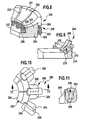
- a fourth embodiment of a yoke body according to the invention which is shown in FIG. 9 and is designated as a whole by 264, is also a segmented ring area 266 with spherical surface areas 268 provided on the segments. Between neighboring There is a gap between the segments.
- a connecting part 270 connects opposite ones Segments of the ring region 266.
- a corresponding element 282 has opposite outer boundary walls on, which are in radial directions, so that between element 282 is sector-like.
- the respective elements 282 point facing the rotor 106 a spherical surface area 284 on and thus represent a segment with a spherical surface.
- the two flange parts 286, 288 each form on adjacent elements 282 Coil receptacles 290 for coils 292, which are then behind the spherical Surfaces 284 sit.
- a coil 292 can be placed on a holding element 296, for example of the first one Put on flange part 286 of element 282. It then becomes an adjacent one Element connected to the element 282 and in particular to this plugged together. As a result, the coil is also placed on the holding element 296 of the adjacent element, which sits on its second flange part 288, postponed. The coils 292 are thereby held on coil receptacles 290, which over two elements 282, namely adjacent elements 282 extend. The magnetic inference then takes place via neighboring ones Elements 282.
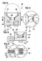
- the yoke body has a plurality of elements 300, which together form the yoke body 298.
- These elements 300 have a spherical surface area facing the rotor 302 on, that is, the yoke body 298 is corresponding segmented.
- the elements 300 continue to have an extent below this spherical area in a holding area 304. This stopping area is thus arranged below an imaginary ball 306, which the spherical surface area 302 of all sectors 300 limited (i.e. the Form surface envelopes of these spherical surface areas 302).
- a recess 308 is formed in each case, for example one per element 300 or two elements 300 assigned To be able to accommodate coil 310.
- the coil receptacle 312 thus formed comprises a holding bridge 314, on which the respective coil 310 is attached or is wound directly (with intermediate insulation).
- a holding element 318 by means of which a Coil holder 320 is formed.
- Coil 322 with a coil axis transverse to the axis of rotation of the rotor and in particular perpendicular to it, with the coil 322 sitting centered.
- Yoke body segments 324 which are located on the holding element 318 each have a spherical surface area 326.
- four segments 324 are provided, two of which opposite segments by the holding element 318 in the manner of a Webs are connected.
- the other two opposite segments are about another Holding element 328 connected, this further holding element 328 via a side surface 330 of the yoke body 316 protrudes.
- the holding element 328 is, for example, U-shaped.
- a coil holder 332 is likewise formed on the holding element 328, a recess 336 between opposite arms 334a, 334b is formed to partially accommodate a coil 338.
- the coil 338 has a coil axis that is transverse and in particular perpendicular to that is the coil 322.
- the coil 338 is therefore outside of a cylindrical region, which the includes spherical surfaces 302, and below the sphere, which is the envelope of these spherical surfaces.
- the coil 322 is within the cylindrical area and below the envelope sphere.
- the yoke body 316 points between the opposite segments 324 has a recess 340 to accommodate the coil holder 320 the coil 322 to form.
- the coil 322 is seated in this recess at least partially.
- FIGS. 16 and 17 In an eighth embodiment of a yoke body according to the invention, which is shown in FIGS. 16 and 17 and there as a whole 342 is again a spherical surface area 344 provided, which faces the runner.
- Coil 346 which is oriented symmetrically with respect to an axis of rotation of the rotor is.
- the coil axis is transverse and in particular perpendicular to this axis of rotation.
- a cross section of this coil 346 extends over substantially the entire width of the yoke body 342.
- a recess 354 is provided which extends over the width of the Yoke body 342 extends so that the coil is also symmetrical Axis of rotation over the width of the yoke body can be positioned in this.
- two coils are provided and the Coil axes of the coils are transverse and in particular perpendicular to one another.
- coils 360 are wound on this yoke body 356, which are toroidal. These coils 360 are of shape of the annular yoke body 356 adapted. Your coil axis lies thereby in the circumferential direction, the coil axis being curved and in particular Is part of a circle. The yoke body 356 as a whole thus forms the Spool retainer.
- the turns are, for example, at an angle to an axis of the yoke body 356 to enable the docking.
- the individual turns 362 can be formed from a flat material, so as to To achieve winding that optimally follows the contour of the yoke body 356.
Landscapes
- Engineering & Computer Science (AREA)
- Power Engineering (AREA)
- Mechanical Engineering (AREA)
- General Engineering & Computer Science (AREA)
- Iron Core Of Rotating Electric Machines (AREA)
- Connection Of Motors, Electrical Generators, Mechanical Devices, And The Like (AREA)
- Synchronous Machinery (AREA)
- Permanent Magnet Type Synchronous Machine (AREA)
- Structures Of Non-Positive Displacement Pumps (AREA)
- Induction Machinery (AREA)
- Windings For Motors And Generators (AREA)
- Motor Or Generator Frames (AREA)
Abstract
Description
Es zeigen:
- Figur 1
- eine perspektivische Schnittansicht eines Ausführungsbeispiels einer erfindungsgemäßen Umwälzpumpe;
- Figur 2
- schematisch eine Teilansicht eines Läufers und eines Stators und die wirkenden Kräfte;
- Figur 3
- eine Teil-Schnittansicht eines Ausführungsbeispiels eines Lagers zur Lagerung des Läufers;
- Figur 4
- eine Draufsicht auf ein erstes Ausführungsbeispiel eines erfindungsgemäßen Rückschlußkörpers;
- Figur 5
- eine perspektivische Teilansicht des Rückschlußkörpers gemäß Figur 4 mit aufgenommenen Wicklungen;
- Figur 6
- eine Variante der Ausführungsform gemäß Figur 5;
- Figur 7
- eine perspektivische Teilansicht eines zweiten Ausführungsbeispiels eines erfindungsgemäßen Rückschlußkörpers;
- Figur 8
- eine perspektivische Teil-Schnittansicht eines dritten Ausführungsbeispiels eines erfindungsgemäßen Rückschlußkörpers;
- Figur 9
- eine Teil-Schnittansicht eines vierten Ausführungsbeispiels eines erfindungsgemäßen Rückschlußkörpers;
- Figur 10
- eine Teil-Draufsicht auf ein fünftes Ausführungsbeispiel eines erfindungsgemäßen Rückschlußkörpers;
- Figur 11
- eine Schnittansicht längs der Linie 11-11 gemäß Figur 10;
- Figur 12
- eine seitliche Schnittansicht eines sechsten Ausführungsbeispiels eines erfindungsgemäßen Rückschlußkörpers;
- Figur 13
- eine Schnittansicht längs der Linie 13-13 gemäß Figur 12;
- Figur 14
- eine seitliche Schnittansicht eines siebten Ausführungsbeispiels eines erfindungsgemäßen Rückschlußkörpers;
- Figur 15
- eine Draufsicht auf den Rückschlußkörper gemäß Figur 14;
- Figur 16
- eine seitliche Schnittansicht eines achten Ausführungsbeispiels eines erfindungsgemäßen Rückschlußkörpers;
- Figur 17
- eine Draufsicht auf den Rückschlußkörper gemäß Figur 16;
- Figur 18
- eine schematische Seitenansicht einer Ausführungsform eines Rückschlußkörperelements, und
- Figur 19
- ein Ausführungsbeispiel einer Toroidalwicklung auf einem Rückschlußkörper.
Claims (39)
- Elektromotor, umfassend einen Läufer (106) und einen Stator (110), wobei der Läufer (106) sphärisch gelagert ist und dem Stator (110) zugewandt sphärisch ausgebildet ist,
dadurch gekennzeichnet, daß der Stator (110) einen magnetischen Rückschlußkörper (114; 204; 234; 248; 264; 280; 298; 316; 342; 356) aufweist, welcher aus einem gepreßten Pulvermaterial hergestellt ist, und daß der Rückschlußkörper dem Läufer (106) zugewandt mindestens segmentweise sphärisch ausgebildet ist. - Elektromotor nach Anspruch 1, dadurch gekennzeichnet, daß der Rückschlußkörper (114) ein kompakter Körper ist oder kompakte Rückschlußkörper-Elemente (224) umfaßt.
- Elektromotor nach Anspruch 1 oder 2, dadurch gekennzeichnet, daß der Rückschlußkörper aus einer Mehrzahl von Rückschlußkörper-Elementen (224) zusammengesetzt ist.
- Elektromotor nach Anspruch 3, dadurch gekennzeichnet, daß benachbarte Rückschlußkörper-Elemente (224) über eine Steckverbindung verbunden sind.
- Elektromotor nach einem der vorangehenden Ansprüche, dadurch gekennzeichnet, daß der Rückschlußkörper (204; 248) eine Mehrzahl von Segmenten (206; 251) umfaßt, welche dem Stator zugewandt jeweils eine sphärische Oberfläche (202; 252) aufweisen.
- Elektromotor nach Anspruch 5, dadurch gekennzeichnet, daß benachbarte Segmente (251) magnetisch getrennt sind.
- Elektromotor nach Anspruch 5 oder 6, dadurch gekennzeichnet, daß zwischen benachbarten Segmenten (251) ein Spalt (253) gebildet ist.
- Elektromotor nach einem der Ansprüche 5 bis 7, dadurch gekennzeichnet, daß Segmente (251) miteinander über einen Rückschlußbereich (25) verbunden sind.
- Elektromotor nach einem der vorangehenden Ansprüche, dadurch gekennzeichnet, daß der Rückschlußkörper (114) den Läufer (106) ringförmig umgibt.
- Elektromotor nach einem der vorangehenden Ansprüche, dadurch gekennzeichnet, daß das Pulvermaterial Eisenkörner umfaßt, welche gegeneinander elektrisch isoliert sind.
- Elektromotor nach einem der vorangehenden Ansprüche, dadurch gekennzeichnet, daß der Rückschlußkörper (204) mindestens eine Spulenaufnahme (208) aufweist.
- Elektromotor nach Anspruch 11, dadurch gekennzeichnet, daß die Spulenaufnahme (208) mit einer elektrischen Isolierung versehen ist und/oder eine aufgenommene Spule (211) zur Spulenaufnahme (208) hin mit einer elektrischen Isolierung versehen ist.
- Elektromotor nach Anspruch 11 oder 12, dadurch gekennzeichnet, daß die mindestens eine Spulenaufnahme (208) so angeordnet und ausgebildet ist, daß aufgenommene Spulen (211) nicht über den sphärischen Bereich des Rückschlußkörpers in Richtung des Läufers (106) hinausragen.
- Elektromotor nach einem der Ansprüche 11 bis 13, dadurch gekennzeichnet, daß ein Luftspalt (128), welcher zwischen dem Läufer (106) und dem sphärischen Bereich (102) des Rückschlußkörpers (114) gebildet ist, spulenfrei ist.
- Elektromotor nach einem der Ansprüche 11 bis 14, dadurch gekennzeichnet, daß der Rückschlußkörper (204; 280) eine Mehrzahl von Ausnehmungen (210; 294) als Spulenaufnahmen oder zur Bildung von Spulenaufnahmen aufweist.
- Elektromotor nach Anspruch 15, dadurch gekennzeichnet, daß eine Ausnehmung (210), welche einen dem Läufer (106) zugewandten Bereich hat, gegenüber der sphärischen Oberfläche (202) des Rückschlußkörpers (204) zurückgesetzt ist.
- Elektromotor nach einem der Ansprüche 11 bis 16, dadurch gekennzeichnet, daß eine Spule (211) auf eine Spulenaufnahme (208) gewickelt ist.
- Elektromotor nach einem der Ansprüche 11 bis 17, dadurch gekennzeichnet, daß eine vorgefertigte Spule auf eine Spulenaufnahme (228) gesteckt ist.
- Elektromotor nach einem der Ansprüche 10 bis 18, dadurch gekennzeichnet, daß eine Spulenaufnahme (208) so dimensioniert ist, daß der Anteil des Rückschlußkörpers (204), welcher im Bereich des erzeugten Magnetfelds der aufgenommenen Spule (211) liegt, wesentlich kleiner ist als der Bereich (202) des Rückschlußkörpers (204), welcher das erzeugte Magnetfeld auf den Läufer (106) hin überträgt.
- Elektromotor nach einem der Ansprüche 10 bis 19, dadurch gekennzeichnet, daß eine Spulenaufnahme so dimensioniert ist, daß ein ausreichender Bereich des Rückschlußkörpers (204) bereitgestellt ist, um Magnetfluß unterhalb der Sättigung zu transportieren.
- Elektromotor nach einem der Ansprüche 10 bis 20, dadurch gekennzeichnet, daß eine Spulenaufnahme (208) so ausgebildet ist, daß eine Spule (211) mit rundem oder näherungsweise rundem Querschnitt aufnehmbar ist.
- Elektromotor nach einem der Ansprüche 10 bis 21, dadurch gekennzeichnet, daß der Rückschlußkörper (204) eine Mehrzahl von benachbarten Ausnehmungen (210) als Spulenaufnahmen (208) aufweist, welche gegenüber der sphärischen Oberfläche (202) zurückgesetzt sind.
- Elektromotor nach Anspruch 22, dadurch gekennzeichnet, daß die Ausnehmungen (210) gleichmäßig verteilt um einen Innenumfang des Rückschlußkörpers (204) angeordnet sind.
- Elektromotor nach Anspruch 22 oder 23, dadurch gekennzeichnet, daß eine Spulenachse einer in der Spulenaufnahme (208) sitzenden Spule (211) im wesentlichen in Umfangsrichtung des Rückschlußkörpers (204) liegt.
- Elektromotor nach Anspruch 22 oder 23, dadurch gekennzeichnet, daß eine Spulenachse einer in der Spulenaufnahme (236) sitzenden Spule (244) im wesentlichen radial ausgerichtet ist.
- Elektromotor nach einem der Ansprüche 10 bis 21, dadurch gekennzeichnet, daß die mindestens eine Spulenaufnahme (264; 274) hinter oder unter dem dem Läufer (106) zugewandten sphärischen Oberflächenbereich (252; 268) des Rückschlußkörpers (248; 264) angeordnet ist.
- Elektromotor nach Anspruch 26, dadurch gekennzeichnet, daß der Rückschlußkörper (24) einen quer zu einer Drehachse (122) des Läufers (106) liegenden Verbindungsbereich (258) aufweist, welcher eine magnetische Querverbindung bereitstellt.
- Elektromotor nach Anspruch 27, dadurch gekennzeichnet, daß die mindestens eine Spulenaufnahme (264) an dem Verbindungsbereich (258) gebildet ist.
- Elektromotor nach einem der vorangehenden Ansprüche, dadurch gekennzeichnet, daß der Läufer ein Käfigläufer ist.
- Elektromotor nach einem der Ansprüche 1 bis 28, dadurch gekennzeichnet, daß der Läufer (106) magnetfelderzeugend ist.
- Elektromotor nach Anspruch 30, dadurch gekennzeichnet, daß der Läufer (106) eine Mehrzahl von Permanentmagneten umfaßt.
- Elektromotor nach einem der Ansprüche 1 bis 28, dadurch gekennzeichnet, daß der Läufer ein Hystereseläufer ist.
- Elektromotor nach einem der Ansprüche 1 bis 12, dadurch gekennzeichnet, daß eine Mehrzahl Spulen (360) als torusförmige Windungen (362) auf dem Rückschlußkörper (356) angeordnet sind.
- Elektromotor nach Anspruch 33, dadurch gekennzeichnet, daß eine Windungsachse im wesentlichen parallel zu einer Umfangsrichtung des Rückschlußkörpers (356) ist.
- Elektromotor nach Anspruch 33 oder 34, dadurch gekennzeichnet, daß der Rückschlußkörper (356) einstückig ausgebildet ist.
- Elektromotor nach einem der Ansprüche 33 bis 35, dadurch gekennzeichnet, daß benachbarte Spulen (360) getrennt geschaltet sind.
- Umwälzpumpe, welche einen Elektromotor gemäß einem der vorangehenden Ansprüche aufweist.
- Umwälzpumpe nach Anspruch 37, dadurch gekennzeichnet, daß eine Trennwand (132) in einem Luftspalt (128) zwischen Läufer (106) und Rückschlußkörper (114) angeordnet ist.
- Umwälzpumpe nach Anspruch 38, dadurch gekennzeichnet, daß der Luftspalt (128) so dimensioniert ist, daß der Läufer (106) in dem Bereich zwischen Trennwand (132) und Läufer (106) nicht wesentlich reibungsgebremst wird.
Applications Claiming Priority (2)
| Application Number | Priority Date | Filing Date | Title |
|---|---|---|---|
| DE10251647 | 2002-10-30 | ||
| DE10251647.2A DE10251647B4 (de) | 2002-10-30 | 2002-10-30 | Elektromotor |
Publications (2)
| Publication Number | Publication Date |
|---|---|
| EP1416607A2 true EP1416607A2 (de) | 2004-05-06 |
| EP1416607A3 EP1416607A3 (de) | 2004-11-10 |
Family
ID=32087345
Family Applications (1)
| Application Number | Title | Priority Date | Filing Date |
|---|---|---|---|
| EP03021154A Ceased EP1416607A3 (de) | 2002-10-30 | 2003-09-23 | Elektromotor mit sphärischem Luftspalt |
Country Status (4)
| Country | Link |
|---|---|
| US (3) | US6897596B2 (de) |
| EP (1) | EP1416607A3 (de) |
| JP (1) | JP2004159494A (de) |
| DE (1) | DE10251647B4 (de) |
Cited By (7)
| Publication number | Priority date | Publication date | Assignee | Title |
|---|---|---|---|---|
| DE102004042034A1 (de) * | 2004-08-26 | 2006-03-16 | Laing, Oliver | Energieversorgungsvorrichtung für ein elektrisches Gerät und Verfahren zur Bereitstellung elektrischer Energie an Komponenten eines elektrischen Geräts |
| RU2330370C2 (ru) * | 2004-08-25 | 2008-07-27 | Эл Джи Электроникс Инк. | Статор электродвигателя |
| US7759836B2 (en) | 2006-06-02 | 2010-07-20 | Itt Manufacturing Enterprises, Inc. | Coil module for a stator of an electric motor, stator, electric motor, circulation pump and method of manufacturing a stator |
| US7887307B2 (en) | 2006-06-02 | 2011-02-15 | Itt Manufacturing Enterprises, Inc. | Circulation pump |
| DE102010051916A1 (de) | 2010-11-11 | 2012-05-16 | Deutsche Vortex Gmbh & Co. Kg | Statoreinheit und Elektromotor |
| US8313315B2 (en) | 2004-11-26 | 2012-11-20 | Itt Manufacturing Enterprises, Inc. | Circulating pump and method for producing a circulating pump |
| US8714934B2 (en) | 2007-11-05 | 2014-05-06 | Itt Manufacturing Enterprises, Inc. | Circulation pump, heating system and method of determining the flow rate of a liquid through a pipe |
Families Citing this family (22)
| Publication number | Priority date | Publication date | Assignee | Title |
|---|---|---|---|---|
| US7884522B1 (en) | 2004-10-25 | 2011-02-08 | Novatorque, Inc. | Stator and rotor-stator structures for electrodynamic machines |
| DE10251647B4 (de) * | 2002-10-30 | 2016-09-15 | Xylem Ip Holdings Llc | Elektromotor |
| WO2006021359A1 (de) * | 2004-08-26 | 2006-03-02 | Laing, Oliver | Kühlungsanordnung für eine elektrisches gerät und verfahren zur flüssigkeitskühlung |
| US8543365B1 (en) | 2004-10-25 | 2013-09-24 | Novatorque, Inc. | Computer-readable medium, a method and an apparatus for designing and simulating electrodynamic machines implementing conical and cylindrical magnets |
| US9093874B2 (en) | 2004-10-25 | 2015-07-28 | Novatorque, Inc. | Sculpted field pole members and methods of forming the same for electrodynamic machines |
| US7982350B2 (en) | 2004-10-25 | 2011-07-19 | Novatorque, Inc. | Conical magnets and rotor-stator structures for electrodynamic machines |
| US8283832B2 (en) | 2004-10-25 | 2012-10-09 | Novatorque, Inc. | Sculpted field pole members and methods of forming the same for electrodynamic machines |
| US8471425B2 (en) | 2011-03-09 | 2013-06-25 | Novatorque, Inc. | Rotor-stator structures including boost magnet structures for magnetic regions having angled confronting surfaces in rotor assemblies |
| US7061152B2 (en) * | 2004-10-25 | 2006-06-13 | Novatorque, Inc. | Rotor-stator structure for electrodynamic machines |
| US8330316B2 (en) | 2011-03-09 | 2012-12-11 | Novatorque, Inc. | Rotor-stator structures including boost magnet structures for magnetic regions in rotor assemblies disposed external to boundaries of conically-shaped spaces |
| US7294948B2 (en) * | 2004-10-25 | 2007-11-13 | Novatorque, Inc. | Rotor-stator structure for electrodynamic machines |
| DE102004058591A1 (de) * | 2004-11-26 | 2006-06-01 | Laing, Oliver | Umwälzpumpe und Verfahren zur Herstellung einer Umwälzpumpe |
| JP4501664B2 (ja) * | 2004-12-08 | 2010-07-14 | 日産自動車株式会社 | 回転電機 |
| FI117582B (fi) * | 2004-12-23 | 2006-11-30 | Abb Oy | Kestomagneettikoneen roottorirakenne |
| US7500531B2 (en) * | 2005-10-03 | 2009-03-10 | Latourneau Technologies Drilling Systems, Inc. | Low speed AC motor for direct drive applications |
| US20070109746A1 (en) * | 2005-11-15 | 2007-05-17 | Klein David A | Liquid cooling of electronic system and method |
| US9000628B1 (en) * | 2013-10-08 | 2015-04-07 | Kuokwa Ho | Ball joint universal rotary motor, a manufacturing method and a working mechanism thereof |
| CN103780041B (zh) * | 2013-10-08 | 2016-08-17 | 何国华 | 球铰万向回转电机及其制造方法、工作方法 |
| US10734878B2 (en) * | 2017-09-27 | 2020-08-04 | Electronics And Telecommunications Research Institute | Spherical wheel motor and control system thereof |
| US10834850B2 (en) * | 2019-01-23 | 2020-11-10 | Dongguan Jianxin Electronic Technology Co., Ltd. | Integrated radiator provided with water chamber, control panel and water pump |
| CN113253167B (zh) * | 2021-05-12 | 2022-03-11 | 北京航空航天大学 | 一种针对软磁薄膜的低频复数磁导率测试装置及方法 |
| EP4490829A1 (de) * | 2022-04-26 | 2025-01-15 | Bomatec Management AG | Elektrischer antrieb mit toroidalem spulenträger |
Family Cites Families (24)
| Publication number | Priority date | Publication date | Assignee | Title |
|---|---|---|---|---|
| US3397331A (en) | 1965-07-20 | 1968-08-13 | Avco Corp | Electrode structure for a magnetohydrodynamic device |
| DE1538717A1 (de) * | 1966-09-07 | 1970-06-11 | Beteiligungs Ag Haustechnik | Elektrische Umlaufmaschine |
| GB1207621A (en) | 1966-09-07 | 1970-10-07 | Accessairsa | Induction motor with spherical air gap |
| AT307236B (de) * | 1969-12-16 | 1973-05-10 | Beteiligungs A G Fuer Haustech | Strömungsmaschine,insbesondere Kreiselpumpe |
| AT309230B (de) * | 1970-10-13 | 1973-08-10 | Standard Magnet Ag | Magnetische Kupplung, insbesondere zum Kuppeln eines Pumpenlaufrades |
| AT335563B (de) * | 1975-01-13 | 1977-03-25 | Vortex Gmbh Dt | Pumpen-motor-einheit |
| GB1553076A (en) * | 1975-06-02 | 1979-09-19 | Dupont Research & Investment S | Electric motor |
| US4297604A (en) * | 1979-05-11 | 1981-10-27 | Gen-Tech, Inc. | Axial air gap alternators/generators of modular construction |
| JPS57183252A (en) | 1981-05-01 | 1982-11-11 | Xerox Corp | Method of producing torque motor stator |
| DE3128304A1 (de) | 1981-07-17 | 1983-02-03 | Karsten 7500 Karlsruhe Laing | Stator fuer kugelmotoren |
| DE3302349A1 (de) | 1983-01-25 | 1984-07-26 | Laing, Oliver, Dipl.-Phys., 7148 Remseck | Sphaerische laeufer fuer elektro-motoren |
| DE3345581A1 (de) * | 1983-12-16 | 1985-06-27 | Robert Bosch Gmbh, 7000 Stuttgart | Elektromaschine, insbesondere als antrieb fuer eine umwaelzpumpe |
| DE3436511A1 (de) * | 1984-10-05 | 1986-04-10 | Robert Bosch Gmbh, 7000 Stuttgart | Elektromaschine, insbesondere als antrieb fuer eine umwaelzpumpe |
| US4661737A (en) * | 1985-08-21 | 1987-04-28 | The Curators Of The University Of Missouri | Electrical machines with multiple axes of rotation |
| US5382859A (en) * | 1992-09-01 | 1995-01-17 | Unique Mobility | Stator and method of constructing same for high power density electric motors and generators |
| US5868134A (en) * | 1993-09-21 | 1999-02-09 | Kabushiki Kaisha Topcon | Retinal disease analyzer |
| JPH07184333A (ja) | 1993-12-24 | 1995-07-21 | Matsushita Electric Ind Co Ltd | 電動機のステータ |
| JP3594468B2 (ja) * | 1997-11-21 | 2004-12-02 | 株式会社ニデック | 眼底画像の解析方法 |
| US6664666B2 (en) * | 1998-12-23 | 2003-12-16 | Engineering Matters, Inc. | Motor assembly allowing output in multiple degrees of freedom |
| JP3048567B1 (ja) * | 1999-02-18 | 2000-06-05 | 沖電気工業株式会社 | 半導体装置の製造方法 |
| DE10022071A1 (de) | 2000-05-06 | 2001-11-15 | Bosch Gmbh Robert | Stator |
| US20040174087A1 (en) | 2000-05-06 | 2004-09-09 | Markus Heidrich | Stator |
| US6651309B2 (en) * | 2001-02-27 | 2003-11-25 | Delphi Technologies, Inc. | Method for fabricating a highly-dense powder iron pressed stator core for use in alternating current generators and electric motors |
| DE10251647B4 (de) * | 2002-10-30 | 2016-09-15 | Xylem Ip Holdings Llc | Elektromotor |
-
2002
- 2002-10-30 DE DE10251647.2A patent/DE10251647B4/de not_active Expired - Lifetime
-
2003
- 2003-08-25 US US10/648,846 patent/US6897596B2/en not_active Expired - Lifetime
- 2003-09-23 EP EP03021154A patent/EP1416607A3/de not_active Ceased
- 2003-10-29 JP JP2003368482A patent/JP2004159494A/ja active Pending
-
2005
- 2005-05-09 US US11/125,536 patent/US20050200232A1/en not_active Abandoned
-
2007
- 2007-03-02 US US11/681,699 patent/US7446449B2/en not_active Expired - Lifetime
Cited By (9)
| Publication number | Priority date | Publication date | Assignee | Title |
|---|---|---|---|---|
| RU2330370C2 (ru) * | 2004-08-25 | 2008-07-27 | Эл Джи Электроникс Инк. | Статор электродвигателя |
| DE102004042034A1 (de) * | 2004-08-26 | 2006-03-16 | Laing, Oliver | Energieversorgungsvorrichtung für ein elektrisches Gerät und Verfahren zur Bereitstellung elektrischer Energie an Komponenten eines elektrischen Geräts |
| US7660120B2 (en) | 2004-08-26 | 2010-02-09 | Itt Manufacturing Enterprises, Inc. | Power supply unit for an electrical appliance and method for making electrical power available at components of an electrical appliance |
| US8313315B2 (en) | 2004-11-26 | 2012-11-20 | Itt Manufacturing Enterprises, Inc. | Circulating pump and method for producing a circulating pump |
| DE102004058593B4 (de) * | 2004-11-26 | 2016-05-12 | Xylem Ip Holdings Llc | Umwälzpumpe |
| US7759836B2 (en) | 2006-06-02 | 2010-07-20 | Itt Manufacturing Enterprises, Inc. | Coil module for a stator of an electric motor, stator, electric motor, circulation pump and method of manufacturing a stator |
| US7887307B2 (en) | 2006-06-02 | 2011-02-15 | Itt Manufacturing Enterprises, Inc. | Circulation pump |
| US8714934B2 (en) | 2007-11-05 | 2014-05-06 | Itt Manufacturing Enterprises, Inc. | Circulation pump, heating system and method of determining the flow rate of a liquid through a pipe |
| DE102010051916A1 (de) | 2010-11-11 | 2012-05-16 | Deutsche Vortex Gmbh & Co. Kg | Statoreinheit und Elektromotor |
Also Published As
| Publication number | Publication date |
|---|---|
| DE10251647A1 (de) | 2004-06-03 |
| EP1416607A3 (de) | 2004-11-10 |
| US20040119371A1 (en) | 2004-06-24 |
| DE10251647B4 (de) | 2016-09-15 |
| US20050200232A1 (en) | 2005-09-15 |
| JP2004159494A (ja) | 2004-06-03 |
| US6897596B2 (en) | 2005-05-24 |
| US20070159024A1 (en) | 2007-07-12 |
| US7446449B2 (en) | 2008-11-04 |
Similar Documents
| Publication | Publication Date | Title |
|---|---|---|
| DE10251647B4 (de) | Elektromotor | |
| DE3427677C2 (de) | ||
| EP2638618B1 (de) | Elektrischer scheibenläufermotor und elektrofahrrad oder pedelec mit scheibenläufermotor | |
| DE69735741T2 (de) | Motor | |
| EP0677914A1 (de) | Transversalflussmaschine | |
| EP1843454A1 (de) | Getriebeeinheit und Werkzeughalter mit einer derartigen Getriebeeinheit | |
| DE69014642T2 (de) | Läufer mit reduzierten ventilationsverlusten. | |
| DE202010015364U1 (de) | Bürstenloser Elektromotor oder Generator in Schalenbauweise | |
| DE102017102242A1 (de) | Verwendung von magnetfeldern in elektromaschinen | |
| DE10217285A1 (de) | Elektromechanischer Energiewandler | |
| DE3730615A1 (de) | Elektrische maschine mit permanentmagnet-erregung | |
| DE3641369C2 (de) | ||
| DE102007056116B4 (de) | Permanenterregte elektrische Maschine | |
| WO2014019688A2 (de) | Stator für eine elektrische maschine, elektrische maschine sowie verfahren zum zusammenbauen einer elektrischen maschine | |
| WO2019149402A1 (de) | Elektromotor | |
| DE2650510B2 (de) | Gleichstrommotor | |
| EP1045505A2 (de) | Elektrischer, gekühlter Scheibenläufermotor | |
| DE4138014C1 (en) | Electromechanical power converter in rotary or linear form - has permanent magnets assembled in rotor driven by AC stator winding with pole elements | |
| DE20217109U1 (de) | Elektromotor | |
| EP2339718A2 (de) | Drehmagnet | |
| DE4411145B4 (de) | Fahrradnabe mit darin angeordnetem Gleichstromgenerator | |
| DE10245015B4 (de) | Elektromotor und Umwälzpumpe | |
| DE10245016B4 (de) | Elektromotor mit sphärisch gelagertem Läufer | |
| DE360533C (de) | Magnetelektrische vielpolige Kleinmaschine | |
| DE10037787A1 (de) | Permanenterregte Synchronmaschine |
Legal Events
| Date | Code | Title | Description |
|---|---|---|---|
| PUAI | Public reference made under article 153(3) epc to a published international application that has entered the european phase |
Free format text: ORIGINAL CODE: 0009012 |
|
| AK | Designated contracting states |
Kind code of ref document: A2 Designated state(s): AT BE BG CH CY CZ DE DK EE ES FI FR GB GR HU IE IT LI LU MC NL PT RO SE SI SK TR |
|
| AX | Request for extension of the european patent |
Extension state: AL LT LV MK |
|
| PUAL | Search report despatched |
Free format text: ORIGINAL CODE: 0009013 |
|
| AK | Designated contracting states |
Kind code of ref document: A3 Designated state(s): AT BE BG CH CY CZ DE DK EE ES FI FR GB GR HU IE IT LI LU MC NL PT RO SE SI SK TR |
|
| AX | Request for extension of the european patent |
Extension state: AL LT LV MK |
|
| 17P | Request for examination filed |
Effective date: 20041125 |
|
| 17Q | First examination report despatched |
Effective date: 20050506 |
|
| AKX | Designation fees paid |
Designated state(s): AT BE BG CH CY CZ DE DK EE ES FI FR GB GR HU IE IT LI LU MC NL PT RO SE SI SK TR |
|
| RAP1 | Party data changed (applicant data changed or rights of an application transferred) |
Owner name: VAILLANT GMBH |
|
| APBN | Date of receipt of notice of appeal recorded |
Free format text: ORIGINAL CODE: EPIDOSNNOA2E |
|
| APBR | Date of receipt of statement of grounds of appeal recorded |
Free format text: ORIGINAL CODE: EPIDOSNNOA3E |
|
| APAF | Appeal reference modified |
Free format text: ORIGINAL CODE: EPIDOSCREFNE |
|
| RAP1 | Party data changed (applicant data changed or rights of an application transferred) |
Owner name: ITT MANUFACTURING ENTERPRISES INC. |
|
| APBT | Appeal procedure closed |
Free format text: ORIGINAL CODE: EPIDOSNNOA9E |
|
| STAA | Information on the status of an ep patent application or granted ep patent |
Free format text: STATUS: THE APPLICATION HAS BEEN REFUSED |
|
| 18R | Application refused |
Effective date: 20120913 |