EP1415892A1 - Servo-Lenkanlage - Google Patents
Servo-Lenkanlage Download PDFInfo
- Publication number
- EP1415892A1 EP1415892A1 EP03021596A EP03021596A EP1415892A1 EP 1415892 A1 EP1415892 A1 EP 1415892A1 EP 03021596 A EP03021596 A EP 03021596A EP 03021596 A EP03021596 A EP 03021596A EP 1415892 A1 EP1415892 A1 EP 1415892A1
- Authority
- EP
- European Patent Office
- Prior art keywords
- hydraulic
- electric motor
- steering
- vehicle
- steering angle
- Prior art date
- Legal status (The legal status is an assumption and is not a legal conclusion. Google has not performed a legal analysis and makes no representation as to the accuracy of the status listed.)
- Granted
Links
Images
Classifications
-
- B—PERFORMING OPERATIONS; TRANSPORTING
- B62—LAND VEHICLES FOR TRAVELLING OTHERWISE THAN ON RAILS
- B62D—MOTOR VEHICLES; TRAILERS
- B62D5/00—Power-assisted or power-driven steering
- B62D5/04—Power-assisted or power-driven steering electrical, e.g. using an electric servo-motor connected to, or forming part of, the steering gear
- B62D5/0442—Conversion of rotational into longitudinal movement
-
- B—PERFORMING OPERATIONS; TRANSPORTING
- B62—LAND VEHICLES FOR TRAVELLING OTHERWISE THAN ON RAILS
- B62D—MOTOR VEHICLES; TRAILERS
- B62D5/00—Power-assisted or power-driven steering
- B62D5/06—Power-assisted or power-driven steering fluid, i.e. using a pressurised fluid for most or all the force required for steering a vehicle
- B62D5/065—Power-assisted or power-driven steering fluid, i.e. using a pressurised fluid for most or all the force required for steering a vehicle characterised by specially adapted means for varying pressurised fluid supply based on need, e.g. on-demand, variable assist
Definitions
- the invention relates to a power steering system for a motor vehicle Torque support by an electric motor, which during one of the Vehicle drivers initiated steering lock in the corresponding direction of rotation controlled a steering angle on the steerable vehicle wheels causing element, in particular a rack or the like, in addition to the shift initiated by the driver.
- the environment is referred to, for example, DE 199 51 548 A1 (in particular Figure 1) referred, in addition, for example, to DE 197 33 032 C1 and EP 1 018 464 A2.
- the "classic" power steering will formed by hydraulic systems, for example in the form of a rack-and-pinion hydraulic steering, the so-called hydraulic steering gear from one of the vehicle drive unit driven hydraulic pump supplied or driven becomes. At least in passenger cars, these are hydraulic steering gears used as a so-called "open center” steering gear, i.e. that the hydraulic oil is constantly pumped around. It is true that high steering performance is transferable and the steering system is characterized by high dynamics, however the power loss is also relatively high, in terms of consumption and the emissions of the vehicle drive unit are unfavorable. Also causes the hydraulic oil constantly flowing at high speed Noises and must be cooled separately in some cases.
- hydraulic power steering systems with closed are cheaper Middle (see, for example, DE 197 33 032 C1), in which a hydraulic There is pressure accumulator, however, these systems are in terms of their Structure and arrangement in the vehicle even more complex than a (disadvantageously) already relatively complex hydraulic steering gear with "open center”.
- hydraulic steering gear with drive an electric motor-hydraulic pump combination which means Hydraulic pump no longer (mechanically direct) from the vehicle drive motor is driven, but by an independent electric motor that with regard to its output advantageously the respective Requirements can be regulated accordingly.
- Servo steering systems with an electric motor are also included downstream mechanical transmission known, for example, on the DE 199 51 548 A1 (in particular FIG. 1).
- This is the mechanical motor assigned as servo support Gearbox in a suitable manner with that of the driver himself actuated steering gear, with the help of which ultimately a steering angle to the steerable vehicle wheels is coupled.
- Characteristic of such systems is that the direction of rotation of the electric motor with the Direction of the steering lock corresponds, i.e. for driving on one The electric motor must turn to the right in the opposite direction turn than when driving on a left turn.
- These servo steering systems offer compared to a hydraulic steering (the known types) a considerable Reduction of consumption and advantageously also allow an "active" Servo support, i.e.
- an active steering return for example, an active steering return. Further they are characterized by their compactness and advantageously require no open hydraulic system. However, it is sometimes very disadvantageous bad steering or lane feedback to the driver. Regarding of the steering feeling transmitted to the driver is one "dead" steering, which is particularly due to the inertia of the electric motor and caused by the friction in the mechanical transmission.
- the invention has the object to improve a power steering system according to the preamble of claim 1, which is characterized according to the above description by a minimized and thus almost optimized energy consumption, with regard to the steering feeling transmitted to the driver ,
- the solution to this problem is characterized in that the electric motor is connected via a hydraulic transmission to the element which causes a steering angle on the steerable vehicle wheels.
- Advantageous training and further education are included in the subclaims.
- the invention is instead of the previously usual mechanical transmission now a hydraulic transmission between which the servo support Offering electric motor that rotates according to the direction of the steering lock is reversible, and ultimately the wheel lock generating element, such as a rack that continues as usual directly by the driver of the vehicle when cornering is provided.
- the driver can connect a hydraulic transmission much better steering feel than the previously provided mechanical gears. The driver thus receives better roadway feedback and can withstand the forces occurring there (especially tire lateral forces) feel better and more directly what a good assessment of the current driving situation is very helpful.
- hydraulic transmission can be relatively simple; so can Common components of known hydraulic steering gear can be used.
- a longitudinally displaceably arranged in a cylinder and Servo pistons that can be loaded with hydraulic medium on both sides which causes a steering angle on the steerable vehicle wheels Element, for example.
- a rack that, as usual, from the driver over the Steering spindle and a pinion provided shifted or relocated will be connected.
- the servo piston depending on the direction of rotation of the electric motor or one of this driven and optionally left-handed or right-handed and thus double-acting hydraulic pump depending on the direction of rotation on one hydraulic pressure is applied to both of its sides while at the same time on the other side of the guided in a cylinder or the like Hydraulic pressure applied to the servo piston is reduced.
- this other Side of the servo piston with the one that then functions as the suction side Side of the double-acting hydraulic pump is essentially direct connected, a closed hydraulic circuit can be implemented with all the associated advantages, such as low construction costs, maximum tightness over the entire service life etc. Of course it may be necessary in this closed Hydraulic circuit to provide a suitable compensation volume or the like.
- the information transmitted to the driver can be further improved. Steering feel, if the said unit of electric motor and hydraulic transmission be decoupled essentially continuously from the power steering system can. This can be done hydraulically in one of the two sides of the servo piston interconnecting short-circuit line with regard to its Flow cross section variable throttle valve may be provided is appropriately controlled by an electronic control unit to a essentially continuous coupling or uncoupling of the torque support to achieve by the electric motor.
- the electronic control unit mentioned can also be the electric motor Appropriate control, then only as long and in such a direction is operated as this by the driver of the vehicle with his steering handle with regard to a desired steering angle of the steerable vehicle wheels is specified, whereby in addition to the direction of rotation also the speed of rotation of the electric motor can be specified appropriately.
- the electronic control unit process different input signals. This includes in particular a signal representing the current steering torque, which with the help of a Torque sensor, for example on an input shaft of the driver actuated steering gear is arranged, can be determined.
- a Torque sensor for example on an input shaft of the driver actuated steering gear is arranged
- the electronic control unit can take into account the current Driving speed of the vehicle and / or its yaw rate.
- Other possible boundary conditions that can be taken into account are the steering angle specified by the driver, the specified steering angle change speed, if necessary, at various points in the hydraulic circuit determined by means of pressure sensors provided there, the Temperature of the electric motor and more.
- a so-called brushless DC motor can preferably be used as the electric motor (“Brushless DC motor”) are used because it is safe and easy allows a controlled step operation, which advantageously also delivered engine torque is changeable. This is also appropriate Assistive force generated by the hydraulic pump when steering in to some extent variable. According to the input variables mentioned above the electric motor can then be operated. In the sense of an advantageous Continuing education can also be variable in terms of funding Hydraulic pump are used in the hydraulic transmission, i.e. from Electric motor are driven. Then the hydraulic pump is a so-called Variable pump, its flow rate at constant drive speed - this is specified by the electric motor driving the pump - is variable.
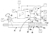
- the attached schematic shows a preferred embodiment of the the present invention, namely only the principal Elements of a power steering system according to the invention for a Motor vehicle.
- the reference number 1 is an electric motor (“M”) referred to, which drives a double-acting hydraulic pump 2.
- M electric motor
- This is arranged in a closed hydraulic circuit 9 to which further includes a cylinder 10 in which a servo piston can be moved longitudinally 3 is arranged.
- This servo piston 3 has a rack 15 connected, just like the servo piston 3 within a housing a steering gear 11 is longitudinally displaceable.
- the interlocking of the Rack 15 is not visible because it is not broken Section of the steering gear housing 11 is located.
- the servo piston 3 together with the rack as in rack and pinion steering systems usually an element which (via intermediate, tie rods, not shown) ultimately a steering angle to the Steerable wheels of the motor vehicle (also not shown) causes.
- the steering gear 11 is driven according to the request or the Specification of the vehicle driver, who operates a steering wheel as usual, whose rotational movement via a steering spindle 12, on the steering wheel opposite end one with the rack 15 of the steering gear, more precisely with their teeth meshing pinion is provided, and over this pinion is transferred to the said rack.
- a torque sensor 4 (TS) is arranged with the help of which the respective steering torque can be determined.
- ⁇ P electroniced electronic control unit 5
- control unit 5 In addition to the steering torque (“TS”), control unit 5 are other input variables 7 or boundary conditions 7 processed or taken into account, for example. (summarized under reference number 7) the vehicle driving speed, the steering angle change speed, the steering angle, the vehicle yaw rate, the temperature of the electric motor 1 and signals from Pressure sensors 8 ("p”), which here are two relevant points in the hydraulic circuit 9 are provided.
- the hydraulic pump 2 is a suitable hydraulic medium either in a chamber lying on the left of the servo piston 3 in the figure 10a of the cylinder 10 or in one in the figure on the right of the servo piston 3 can promote lying chamber 10b of the cylinder 10, depending on from the pump delivery direction, which is directly related to the direction of rotation of the its direction of rotation reversible electric motor 1 is coupled.
- the (Left) chamber 10a with the first (left) side of the hydraulic pump 2 over a hydraulic line 9a and the (right) chamber 10a with the second (Right) side of the hydraulic pump 9 via a hydraulic line 9b connected.
- the “support service” is applied by the electric motor 1, which as described above So-called “hydraulic transmission”, which is essentially through the hydraulic pump 2 and the cylinder 10 is formed with the servo piston 3, with the causing a steering angle on the steerable vehicle wheels Element, namely here the rack 15 of the steering gear 11 connected is.
- This servo support described by the servo piston 3 is intended be extensively changeable in terms of their intensity, which is why a so-called short-circuit line between the two hydraulic lines 9a and 9b 9c is provided, which is arranged quasi parallel to the cylinder 10 connects these two hydraulic lines 9a and 9b together or the hydraulically connects both sides of the servo piston 3.
- this short-circuit line 9c is one with regard to its flow cross section variable throttle valve 14 provided by a suitable Actuating unit 14a can be set specifically. Is this throttle valve 14 completely closed, so when operating the hydraulic pump 2 (or of the electric motor 1) the pumped hydraulic medium as a function of the current conveying direction completely into the respective chamber 10a or 10b of the cylinder 10 promoted.
- the throttle valve 14 is fully opened, so there is practically no hydraulic medium get into the respective chamber 10a or 10b of the cylinder, instead it becomes the hydraulic medium in a small short circuit essentially completely circulated via the short-circuit line 9c, so that practically no pressure build-up or pressure reduction in the chambers 10a or 10b of the cylinder 10 takes place and consequently no servo assistance when the steering is initiated by the driver.
- the vehicle driver advantageously having an optimal one Receives steering feedback
- the first-mentioned state can be for parking of the vehicle can be stopped. In this case it is Steering feedback is less satisfactory, but this is in irrelevant to this driving or operating condition.
- throttle valve 14 Via a variation of the flow cross-section in the short-circuit line 9c provided throttle valve 14 can thus be a practical stepless variation of the servo support by the servo piston 3 be made so that in or via the so-called hydraulic Gearbox through the hydraulic pump 2, the cylinder 10 with the servo piston 3 and the hydraulic circuit 9 is formed, one essentially continuous coupling or uncoupling of the torque support the electric motor 1 is possible during a steering process.
Abstract
Description
Die Lösung dieser Aufgabe ist dadurch gekennzeichnet, dass der Elektromotor über ein hydraulisches Getriebe mit dem einen Einschlagwinkel an den lenkbaren Fahrzeug-Rädern hervorrufenden Element verbunden ist. Vorteilhafte Aus- und Weiterbildungen sind Inhalt der Unteransprüche.
Claims (7)
- Servo-Lenkanlage für ein Kraftfahrzeug mit Momentenunterstützung durch einen Elektromotor (1), der während eines vom Fahrzeug-Fahrer initiierten Lenkeinschlags im entsprechenden Drehsinn angesteuert ein einen Einschlagwinkel an den lenkbaren Fahrzeug-Rädern hervorrufendes Element, insbesondere eine Zahnstange oder dgl., zusätzlich zur durch den Fahrer veranlassten Verlagerung mit verlagert,
dadurch gekennzeichnet, dass der Elektromotor (1) über ein hydraulisches Getriebe mit dem einen Einschlagwinkel an den lenkbaren Fahrzeug-Rädern hervorrufenden Element verbunden ist. - Servo-Lenkanlage nach Anspruch 1,
dadurch gekennzeichnet, dass das hydraulische Getriebe durch einen geschlossenen Hydraulik-Kreislauf (9) mit einer vom in seinem Drehsinn veränderbaren Elektromotor (1) angetriebenen wahlweise linksdrehenden oder rechtsdrehenden und somit zweiseitig wirksamen Hydraulikpumpe (2) gebildet ist, die einen mit dem einen Einschlagwinkel an den lenkbaren Fahrzeug-Rädern hervorrufende Element verbundenen Servo-Kolben (3) drehsinnabhängig auf einer seiner beiden Seiten mit Hydraulikdruck beaufschlagt und gleichzeitig den auf der anderen Seite des in einem Zylinder (10) oder dgl. geführten Servo-Kolbens (3) anliegenden Hydraulikdruck abbaut. - Servo-Lenkanlage nach Anspruch 1 oder 2,
gekennzeichnet durch einen bürstenlosen Gleichstrommotor ("brushless DC-Motor") als Elektromotor (1). - Servo-Lenkanlage nach einem der vorangegangenen Ansprüche,
dadurch gekennzeichnet, dass über das hydraulische Getriebe eine im wesentlichen stufenlose Zukopplung oder Abkopplung der Momentenunterstützung durch den Elektromotor (1) umsetzbar ist. - Servo-Lenkanlage nach einem der vorangegangenen Ansprüche,
dadurch gekennzeichnet, dass in einer die beiden Seiten des Servo-Kolbens (3) hydraulisch miteinander verbindenden Kurzschluss-Leitung (9c) ein hinsichtlich seines Durchflussquerschnitts veränderliches Drosselventil (14) vorgesehen ist, das von einer elektronischen Steuereinheit (5) geeignet angesteuert wird, um eine im wesentlichen. stufenlose Zukopplung oder Abkopplung der Momentenunterstützung durch den Elektromotor (1) zu erzielen. - Servo-Lenkanlage nach einem der vorangegangenen Ansprüche,
dadurch gekennzeichnet, dass die Hydraulikpumpe (2) hinsichtlich ihrer Förderleistung bei konstanter Antriebsdrehzahl und somit konstanter Drehzahl des Elektromotors (1) variabel ist. - Servo-Lenkanlage nach einem der vorangegangenen Ansprüche,
dadurch gekennzeichnet, dass in der elektronischen Steuereinheit (5) neben dem vorliegenden Lenkmoment (TS) weitere Randbedingungen (7) berücksichtigt werden, so die Fzg.-Fahrgeschwindigkeit und/oder die Lenkwinkel-Änderungsgeschwindigkeit und/oder der Lenkwinkel und/oder die Fzg.-Giergeschwindigkeit und/oder die Temperatur des Elektromotors (1) und/oder die im Hydraulik-Kreislauf (9) vorliegenden Druckverhältnisse.
Applications Claiming Priority (2)
| Application Number | Priority Date | Filing Date | Title |
|---|---|---|---|
| DE2002150300 DE10250300A1 (de) | 2002-10-29 | 2002-10-29 | Servo-Lenkanlage |
| DE10250300 | 2002-10-29 |
Publications (2)
| Publication Number | Publication Date |
|---|---|
| EP1415892A1 true EP1415892A1 (de) | 2004-05-06 |
| EP1415892B1 EP1415892B1 (de) | 2006-08-30 |
Family
ID=32087264
Family Applications (1)
| Application Number | Title | Priority Date | Filing Date |
|---|---|---|---|
| EP20030021596 Expired - Lifetime EP1415892B1 (de) | 2002-10-29 | 2003-09-25 | Servo-Lenkanlage |
Country Status (2)
| Country | Link |
|---|---|
| EP (1) | EP1415892B1 (de) |
| DE (2) | DE10250300A1 (de) |
Cited By (2)
| Publication number | Priority date | Publication date | Assignee | Title |
|---|---|---|---|---|
| CN101846109A (zh) * | 2010-04-30 | 2010-09-29 | 太原理工大学 | 一种二通流量连续控制阀 |
| WO2016083063A1 (de) * | 2014-11-26 | 2016-06-02 | Robert Bosch Automotive Steering Gmbh | Lenksystem für ein kraftfahrzeug und verfahren zum entlüften eines lenksystems für ein kraftfahrzeug |
Families Citing this family (4)
| Publication number | Priority date | Publication date | Assignee | Title |
|---|---|---|---|---|
| DE102004009817A1 (de) * | 2004-02-28 | 2005-09-15 | Zf Lenksysteme Gmbh | Servounterstüztes Lenksystem für ein Kraftfahrzeug und Verfahren zum Betrieb des Lenksystems |
| JP4629533B2 (ja) | 2005-08-22 | 2011-02-09 | 日立オートモティブシステムズ株式会社 | 液圧制御装置及びその製造方法 |
| DE102008036261B4 (de) * | 2008-08-04 | 2020-08-27 | Zf Automotive Germany Gmbh | Verfahren zur Steuerung einer Leistungseinheit eines Fahrzeug-Lenksystems sowie Fahrzeug-Lenksystem |
| DE102012112483B4 (de) * | 2012-12-18 | 2021-07-01 | Robert Bosch Gmbh | Verfahren zum Betreiben eines hydraulisch unterstützten Lenksystems und hydraulisch unterstütztes Lenksystem |
Citations (5)
| Publication number | Priority date | Publication date | Assignee | Title |
|---|---|---|---|---|
| US5267627A (en) * | 1992-03-27 | 1993-12-07 | Imra America, Inc. | Vehicle stability augmentation system |
| DE19733032C1 (de) | 1997-07-31 | 1998-09-24 | Mercedes Benz Lenkungen Gmbh | Hydraulische Servolenkung mit geschlossener Mitte |
| DE19951548A1 (de) | 1998-10-26 | 2000-04-27 | Honda Motor Co Ltd | Elektrische Servolenkvorrichtung |
| EP1018464A2 (de) | 1999-01-05 | 2000-07-12 | Ford Global Technologies, Inc. | Verfahren und Vorrichtung für eine Servolenkung mit veränderlicher Unterstützung |
| WO2001054960A1 (en) * | 2000-01-27 | 2001-08-02 | Dana Corporation | Precision electro-hydraulic actuator positioning system |
-
2002
- 2002-10-29 DE DE2002150300 patent/DE10250300A1/de not_active Withdrawn
-
2003
- 2003-09-25 DE DE50304835T patent/DE50304835D1/de not_active Expired - Lifetime
- 2003-09-25 EP EP20030021596 patent/EP1415892B1/de not_active Expired - Lifetime
Patent Citations (5)
| Publication number | Priority date | Publication date | Assignee | Title |
|---|---|---|---|---|
| US5267627A (en) * | 1992-03-27 | 1993-12-07 | Imra America, Inc. | Vehicle stability augmentation system |
| DE19733032C1 (de) | 1997-07-31 | 1998-09-24 | Mercedes Benz Lenkungen Gmbh | Hydraulische Servolenkung mit geschlossener Mitte |
| DE19951548A1 (de) | 1998-10-26 | 2000-04-27 | Honda Motor Co Ltd | Elektrische Servolenkvorrichtung |
| EP1018464A2 (de) | 1999-01-05 | 2000-07-12 | Ford Global Technologies, Inc. | Verfahren und Vorrichtung für eine Servolenkung mit veränderlicher Unterstützung |
| WO2001054960A1 (en) * | 2000-01-27 | 2001-08-02 | Dana Corporation | Precision electro-hydraulic actuator positioning system |
Cited By (4)
| Publication number | Priority date | Publication date | Assignee | Title |
|---|---|---|---|---|
| CN101846109A (zh) * | 2010-04-30 | 2010-09-29 | 太原理工大学 | 一种二通流量连续控制阀 |
| CN101846109B (zh) * | 2010-04-30 | 2012-08-29 | 太原理工大学 | 一种二通流量连续控制阀 |
| WO2016083063A1 (de) * | 2014-11-26 | 2016-06-02 | Robert Bosch Automotive Steering Gmbh | Lenksystem für ein kraftfahrzeug und verfahren zum entlüften eines lenksystems für ein kraftfahrzeug |
| DE102014117327A1 (de) | 2014-11-26 | 2016-06-02 | Robert Bosch Automotive Steering Gmbh | Lenksystem für ein Kraftfahrzeug und Verfahren zum Entlüften eines Lenksystems für ein Kraftfahrzeug |
Also Published As
| Publication number | Publication date |
|---|---|
| EP1415892B1 (de) | 2006-08-30 |
| DE10250300A1 (de) | 2004-05-19 |
| DE50304835D1 (de) | 2006-10-12 |
Similar Documents
| Publication | Publication Date | Title |
|---|---|---|
| DE602004006261T2 (de) | Fahrzeuglenksystem mit hinterem Lenksteuermechanismus | |
| DE60307161T2 (de) | Aktives Vorderrad-Lenkungs-Stellglied und Verfahren zum Steuern eines Fahrzeugs | |
| EP1251059B1 (de) | Verfahren zum Steuern eines Servolenksystems | |
| EP1480864B1 (de) | Hydraulische servolenkung | |
| EP1508494B1 (de) | Hilfskraftunterstütztes Lenksystem für ein Kraftfahrzeug, mit hydraulischer offener Mitte | |
| DE4243267B4 (de) | Lenkgetriebe | |
| DE4040003A1 (de) | Servolenkung fuer fahrzeuge | |
| EP1556270A1 (de) | Elektro-hydrodynamische überlagerungslenkung | |
| DE10159330A1 (de) | Reaktionsmomentsimulator für ein Lenkrad einer Fahrzeuglenkung | |
| DE10351618B4 (de) | Nutzfahrzeuglenkung | |
| EP1461236B1 (de) | Lenksystem für kraftfahrzeuge | |
| DE3536563A1 (de) | Lenkvorrichtung fuer hydrostatische oder mechanische lenkanlagen | |
| EP2539204A1 (de) | Lenksystem mit hydraulischer lenksäule | |
| EP1415892B1 (de) | Servo-Lenkanlage | |
| DE19935073A1 (de) | Steer-by-wire-Lenkung mit hydraulischem Druckspeicher | |
| DE10046168A1 (de) | Lenksystem | |
| EP1508498B1 (de) | Lenksystem für ein Kraftfahrzeug mit einer Servolenkeinrichtung | |
| DE10256306A1 (de) | Hydraulische Servolenkung | |
| DE10135862A1 (de) | Fahrzeuglenkung | |
| DE10353084A1 (de) | Hilfskraftunterstütztes Lenksystem eines Kraftfahrzeugs | |
| DE10351768A1 (de) | Lenksystem für ein Kraftfahrzeug mit einer Servolenkeinrichtung | |
| DE102008047545A1 (de) | Elektrohydraulische Lenkung und Verfahren zum Betrieb dafür | |
| DE10320846A1 (de) | Lenkungsvorrichtung für Kraftfahrzeuge | |
| DE102004007619A1 (de) | Servolenkventil | |
| EP1588926A2 (de) | Lenkgetriebe mit Überlagerungslenkung |
Legal Events
| Date | Code | Title | Description |
|---|---|---|---|
| PUAI | Public reference made under article 153(3) epc to a published international application that has entered the european phase |
Free format text: ORIGINAL CODE: 0009012 |
|
| AK | Designated contracting states |
Kind code of ref document: A1 Designated state(s): AT BE BG CH CY CZ DE DK EE ES FI FR GB GR HU IE IT LI LU MC NL PT RO SE SI SK TR |
|
| AX | Request for extension of the european patent |
Extension state: AL LT LV MK |
|
| 17P | Request for examination filed |
Effective date: 20040925 |
|
| AKX | Designation fees paid |
Designated state(s): DE FR GB IT |
|
| GRAP | Despatch of communication of intention to grant a patent |
Free format text: ORIGINAL CODE: EPIDOSNIGR1 |
|
| GRAS | Grant fee paid |
Free format text: ORIGINAL CODE: EPIDOSNIGR3 |
|
| GRAA | (expected) grant |
Free format text: ORIGINAL CODE: 0009210 |
|
| AK | Designated contracting states |
Kind code of ref document: B1 Designated state(s): DE FR GB IT |
|
| REG | Reference to a national code |
Ref country code: GB Ref legal event code: FG4D Free format text: NOT ENGLISH |
|
| REF | Corresponds to: |
Ref document number: 50304835 Country of ref document: DE Date of ref document: 20061012 Kind code of ref document: P |
|
| GBT | Gb: translation of ep patent filed (gb section 77(6)(a)/1977) |
Effective date: 20060923 |
|
| ET | Fr: translation filed | ||
| PLBE | No opposition filed within time limit |
Free format text: ORIGINAL CODE: 0009261 |
|
| STAA | Information on the status of an ep patent application or granted ep patent |
Free format text: STATUS: NO OPPOSITION FILED WITHIN TIME LIMIT |
|
| 26N | No opposition filed |
Effective date: 20070531 |
|
| REG | Reference to a national code |
Ref country code: FR Ref legal event code: PLFP Year of fee payment: 13 |
|
| PGFP | Annual fee paid to national office [announced via postgrant information from national office to epo] |
Ref country code: GB Payment date: 20150924 Year of fee payment: 13 |
|
| PGFP | Annual fee paid to national office [announced via postgrant information from national office to epo] |
Ref country code: FR Payment date: 20150928 Year of fee payment: 13 |
|
| PGFP | Annual fee paid to national office [announced via postgrant information from national office to epo] |
Ref country code: IT Payment date: 20150924 Year of fee payment: 13 |
|
| PGFP | Annual fee paid to national office [announced via postgrant information from national office to epo] |
Ref country code: DE Payment date: 20151031 Year of fee payment: 13 |
|
| REG | Reference to a national code |
Ref country code: DE Ref legal event code: R119 Ref document number: 50304835 Country of ref document: DE |
|
| GBPC | Gb: european patent ceased through non-payment of renewal fee |
Effective date: 20160925 |
|
| REG | Reference to a national code |
Ref country code: FR Ref legal event code: ST Effective date: 20170531 |
|
| PG25 | Lapsed in a contracting state [announced via postgrant information from national office to epo] |
Ref country code: DE Free format text: LAPSE BECAUSE OF NON-PAYMENT OF DUE FEES Effective date: 20170401 Ref country code: FR Free format text: LAPSE BECAUSE OF NON-PAYMENT OF DUE FEES Effective date: 20160930 Ref country code: GB Free format text: LAPSE BECAUSE OF NON-PAYMENT OF DUE FEES Effective date: 20160925 |
|
| PG25 | Lapsed in a contracting state [announced via postgrant information from national office to epo] |
Ref country code: IT Free format text: LAPSE BECAUSE OF NON-PAYMENT OF DUE FEES Effective date: 20160925 |