EP1415857A2 - Volant de véhicule - Google Patents
Volant de véhicule Download PDFInfo
- Publication number
- EP1415857A2 EP1415857A2 EP20030022977 EP03022977A EP1415857A2 EP 1415857 A2 EP1415857 A2 EP 1415857A2 EP 20030022977 EP20030022977 EP 20030022977 EP 03022977 A EP03022977 A EP 03022977A EP 1415857 A2 EP1415857 A2 EP 1415857A2
- Authority
- EP
- European Patent Office
- Prior art keywords
- switch
- steering wheel
- vehicle steering
- carrier
- actuating
- Prior art date
- Legal status (The legal status is an assumption and is not a legal conclusion. Google has not performed a legal analysis and makes no representation as to the accuracy of the status listed.)
- Withdrawn
Links
Images


Classifications
-
- B—PERFORMING OPERATIONS; TRANSPORTING
- B60—VEHICLES IN GENERAL
- B60R—VEHICLES, VEHICLE FITTINGS, OR VEHICLE PARTS, NOT OTHERWISE PROVIDED FOR
- B60R21/00—Arrangements or fittings on vehicles for protecting or preventing injuries to occupants or pedestrians in case of accidents or other traffic risks
- B60R21/02—Occupant safety arrangements or fittings, e.g. crash pads
- B60R21/16—Inflatable occupant restraints or confinements designed to inflate upon impact or impending impact, e.g. air bags
- B60R21/20—Arrangements for storing inflatable members in their non-use or deflated condition; Arrangement or mounting of air bag modules or components
- B60R21/203—Arrangements for storing inflatable members in their non-use or deflated condition; Arrangement or mounting of air bag modules or components in steering wheels or steering columns
- B60R21/2035—Arrangements for storing inflatable members in their non-use or deflated condition; Arrangement or mounting of air bag modules or components in steering wheels or steering columns using modules containing inflator, bag and cover attachable to the steering wheel as a complete sub-unit
- B60R21/2037—Arrangements for storing inflatable members in their non-use or deflated condition; Arrangement or mounting of air bag modules or components in steering wheels or steering columns using modules containing inflator, bag and cover attachable to the steering wheel as a complete sub-unit the module or a major component thereof being yieldably mounted, e.g. for actuating the horn switch or for protecting the driver in a non-deployment situation
-
- B—PERFORMING OPERATIONS; TRANSPORTING
- B60—VEHICLES IN GENERAL
- B60Q—ARRANGEMENT OF SIGNALLING OR LIGHTING DEVICES, THE MOUNTING OR SUPPORTING THEREOF OR CIRCUITS THEREFOR, FOR VEHICLES IN GENERAL
- B60Q5/00—Arrangement or adaptation of acoustic signal devices
- B60Q5/001—Switches therefor
- B60Q5/003—Switches therefor mounted on the steering wheel
Definitions
- the invention relates to a vehicle steering wheel with switches and actuators to operate the switches.
- switches can be, for example Horn contact switch and multifunction switch to trigger the horn or to control functions such as on-board computers, radio etc. from the steering wheel out.
- the switches are common for easy manufacture of the vehicle steering wheel on a common moving part, preferably on a carrier in Form of a printed circuit board, attached.
- a so-called "Floating-horn” gas bag module with which most vehicle steering wheels nowadays are equipped. This is so called because the entire airbag module is slidably mounted in the axial direction of the steering wheel and for Triggering the horn moved by pressing the cover of the gas bag module can be used to operate the horn contact switch.
- the multi-function switch are also attached to the gas bag module, it can happen that when the multi-function switch is pressed firmly, the horn is unintentionally is triggered.
- the invention provides a simple and reliable solution to the above mentioned problem in the form of a vehicle steering wheel, with a first switch and a first actuating element for actuating the first switch, with a second switch and a second actuating element for actuating the second switch, with a carrier, through the second actuator for actuating the second switch is displaceable in an actuation direction and on which the first switch is mounted, and with a base body, relative to which the carrier is slidably mounted in the direction of actuation, the first actuating element is provided with a stop element on the base body strikes when the first actuator to the full Operation of the first switch is shifted, and the one to operate the second switch leading displacement of the carrier by means of the first Actuator prevented.
- the stop element ensures that a so-called "overpressing" the first actuating element, for example a button for a multi-function switch, is no longer possible.
- the second actuating element that is for example, the button to trigger the horn, pressed, the move common carrier to operate the horn switch while the multifunction button through the stop element on another movement remains hindered. This causes the unwanted actuation of the second switch actuation of the first switch excluded.
- the carrier has an upper side and a bottom, with the first switch on the top and the second Switch is attached to the bottom.
- the two switches can be arranged directly one above the other, which enables a simplified and short cable routing.
- the second actuating element an airbag module (floating-hom airbag module) slidably mounted in the vehicle steering wheel and the second switch is a horn contact switch. So that entire surface of the gas bag module as an actuating surface for triggering the Horn can be used. This means that the horn is activated quickly Hazard possible.
- the first actuating element is Slidable on a side extension of the gas bag module stored.
- the first and the second actuating element form a common assembly unit. that can be prefabricated and simply into that Vehicle steering wheel is to be installed.
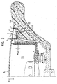
- FIG 1 is a vehicle steering wheel with a foam-coated steering wheel skeleton 122 and a floating hom gas bag module 110.
- the steering wheel skeleton 122 forms a base body and has a cup-shaped recess 100 equipped, in which the gas bag module 110 in the in Figure 1 by the arrow B indicated direction slidably mounted parallel to the longitudinal axis of the steering wheel is.
- the gas bag module 110 has a trough-shaped module housing that is open at the top 114 in which a container 115 sits.
- a cover 8 which is tearable is around a gas bag housed inside the container (in the figures indicated by 116). It is also inside the container 115 accommodates a gas generator 112, which with its generator flange 113 on Module housing 114 is attached, being between the generator flange 113 and the container 115 and the gas bag 116 are also attached to the module housing 114 are.
- At an upper edge 120 of the module housing 114 is in the area of Spokes of the steering wheel, preferably symmetrical left and right, one each radial extension 124 formed on which a carrier 134 for a first Switch 2 and a second switch 132 is attached.
- the switches 2, 132 are each provided with a pressure plunger 150 or 200, which is used to actuate the Switch can be pressed.
- the carrier 134 preferably has a printed circuit board on the upper side thereof the first switch 2 with the pressure plunger 150 pointing upwards, and on the latter Underside of the second switch 132 with the pressure plunger 200 pointing downward, is appropriate.
- the second switch 132 protrudes through an opening in the extension 124, so that the pressure plunger 200 on one in the foam of the steering wheel skeleton 122 trained flat abutment surface 160 can rest under the tail 124 substantially perpendicular to the longitudinal axis of the vehicle steering wheel extends.
- first actuating element in the form of a on the extension 124 Pushbutton 4 slidably mounted in actuation direction B.
- the key 4 has on its underside facing the printed circuit board 134 at least one rib 140, with who operate the switch 2 when moving via the pressure plunger 150 can.
- the switch 2 is used to trigger a so-called multifunctional feature for example for the operation of on-board computers, radio, navigation system or the like, so that the button 4 and the switch 2 together part are a multi-function switch unit, of which only one in the section of Figure 1 Key / switch combination is shown.
- the multi-function switch unit can have several such key / switch combinations, one after the other can be arranged.
- at least the rib has 140 a button 4 a stop element in the form of a protruding downward Extension 9, which extends through an opening in the extension 124.
- the switch 132 serves as a horn contact switch for triggering the horn. To a force must be exerted on the cover 8 when it is actuated, and indeed in the direction of actuation B. As a result, the slidably mounted Module housing 114 from its rest position, as shown in Figure 1, in the actuating position, which is shown in Figure 2, shifted, of course the carrier 134 is also carried in the direction of actuation.
- the horn contact switch 132 is activated by the pressure plunger 200 Stop surface 160 actuated. To keep the actuation path as short as possible reach, the pressure plunger 200 is preferably already in the rest position the abutment surface 160, as shown in Figure 1.
- the module housing 114 After the cover 8 is released, the module housing 114 returns as a result a restoring force exerted by return springs 118 back to the rest position back.
- the button 4 is pressed down to trigger a multifunctional feature in the actuating direction B, the associated switch 2 is actuated by the rib 140 by the pressure plunger 150.
- the actuation path W 2 (see FIG. 2) of the switch 2, which in the embodiment shown is 1.5 mm, for example, the extension 9 comes to a stop on the stop surface 160.
- the button 4 can therefore not be pressed further down. However, this reliably prevents the module housing 114 from being displaced when the button 4 is pressed further, and the horn contact switch 132 would thus be actuated inadvertently by "pressing" the button 4.
- the actuation path W 132 of the horn contact switch 132 preferably corresponds to the actuation path W 2 of the switch 2 of the multifunction switch unit, so that the carrier 134 is never set in motion when the switch 2 is actuated.
- switch 2 is also equipped with a return spring.
- the force of this return spring is significantly less than that of the return spring 118, so that when you press button 4, the return spring in Switch 2 is pressed together.
- the switches 2, 132 are in the described embodiment as microswitches shown, for example as NC, NO or combinations can be carried out from it. However, there are other embodiments conceivable in which the switch 2, for example by reed contacts or simple contact pairs are represented, of which one contact at the PCB 134, the other on or through one of the actuator displaceable intermediate element can be attached.
- the first actuating element 4 is in the embodiment described Extension 124 of the module housing 114 is mounted and thus relative to the carrier 134 displaceable.
- the first actuating element could also be directly on Carrier or be stored on the base body.
- the invention thus creates a combination of multi-function switch unit and floating horn gas bag module, which do not have separate switch carriers needed for decoupling motion and still the possibility of one excludes unwanted horns when using multifunction switches.
Applications Claiming Priority (4)
| Application Number | Priority Date | Filing Date | Title |
|---|---|---|---|
| DE20216793U | 2002-10-30 | ||
| DE20216793 | 2002-10-30 | ||
| DE20309521U DE20309521U1 (de) | 2002-10-30 | 2003-06-20 | Fahrzeuglenkrad |
| DE20309521U | 2003-06-20 |
Publications (1)
| Publication Number | Publication Date |
|---|---|
| EP1415857A2 true EP1415857A2 (fr) | 2004-05-06 |
Family
ID=32094885
Family Applications (1)
| Application Number | Title | Priority Date | Filing Date |
|---|---|---|---|
| EP20030022977 Withdrawn EP1415857A2 (fr) | 2002-10-30 | 2003-10-10 | Volant de véhicule |
Country Status (2)
| Country | Link |
|---|---|
| US (1) | US6849816B2 (fr) |
| EP (1) | EP1415857A2 (fr) |
Cited By (1)
| Publication number | Priority date | Publication date | Assignee | Title |
|---|---|---|---|---|
| EP1623885A3 (fr) * | 2004-08-03 | 2007-07-18 | TRW Automotive Safety Systems GmbH | Module de coussin gonflable |
Families Citing this family (6)
| Publication number | Priority date | Publication date | Assignee | Title |
|---|---|---|---|---|
| DE20116306U1 (de) * | 2001-10-05 | 2002-02-14 | Trw Automotive Safety Sys Gmbh | Fahrzeuglenkrad |
| DE20216754U1 (de) * | 2002-10-30 | 2003-03-20 | Trw Automotive Safety Sys Gmbh | Gassackmodul und Fahrzeuglenkrad mit einem Gassackmodul |
| DE20216755U1 (de) * | 2002-10-30 | 2003-03-20 | Trw Automotive Safety Sys Gmbh | Lenkrad |
| JP4907159B2 (ja) * | 2005-11-22 | 2012-03-28 | タカタ株式会社 | エアバッグ装置及びステアリングホイール |
| WO2008060193A1 (fr) * | 2006-11-13 | 2008-05-22 | Autoliv Development Ab | Agencement de recouvrement de coussin de sécurité gonflable |
| DE202009018412U1 (de) * | 2009-02-04 | 2011-09-28 | Takata-Petri Ag | Lenkradbaugruppe für ein Kraftfahrzeug |
Family Cites Families (12)
| Publication number | Priority date | Publication date | Assignee | Title |
|---|---|---|---|---|
| US4518836A (en) * | 1984-04-17 | 1985-05-21 | United Technologies Automotive, Inc. | Control pod and switch assembly |
| US4590340A (en) * | 1985-01-29 | 1986-05-20 | Nihon Plast Co., Ltd. | Steering wheel assembly for vehicles |
| US4872364A (en) * | 1987-10-27 | 1989-10-10 | Toyoda Gosei Co., Ltd. | Steering wheel |
| US5303952A (en) * | 1992-12-23 | 1994-04-19 | United Technologies Automotive, Inc. | Electric signalling in a supplemental vehicle restraint system |
| US5627352A (en) * | 1994-09-28 | 1997-05-06 | Toyoda Gosei Co., Ltd. | Steering wheel |
| IT1284667B1 (it) * | 1996-07-16 | 1998-05-21 | Bruzolo Manifatt Gestind Mb | Volante di sterzo per autoveicoli con interruttore per il comando di di un avvisatore acustico. |
| JPH11329157A (ja) * | 1998-05-21 | 1999-11-30 | Alps Electric Co Ltd | スイッチ装置 |
| JP3719861B2 (ja) * | 1998-11-12 | 2005-11-24 | アルプス電気株式会社 | ステアリング装置 |
| DE29918483U1 (de) * | 1999-10-21 | 2000-03-02 | Trw Automotive Safety Sys Gmbh | Fahrzeuglenkrad |
| DE19956872B4 (de) | 1999-11-26 | 2005-09-01 | Audi Ag | Lenkrad für ein Kraftfahrzeug |
| JP3789284B2 (ja) * | 2000-04-28 | 2006-06-21 | アルプス電気株式会社 | 車両のハンドル用スイッチユニット |
| DE20010543U1 (de) | 2000-06-14 | 2001-02-22 | Trw Automotive Safety Sys Gmbh | Multifunktionslenkrad |
-
2003
- 2003-10-10 EP EP20030022977 patent/EP1415857A2/fr not_active Withdrawn
- 2003-10-23 US US10/692,218 patent/US6849816B2/en not_active Expired - Fee Related
Cited By (1)
| Publication number | Priority date | Publication date | Assignee | Title |
|---|---|---|---|---|
| EP1623885A3 (fr) * | 2004-08-03 | 2007-07-18 | TRW Automotive Safety Systems GmbH | Module de coussin gonflable |
Also Published As
| Publication number | Publication date |
|---|---|
| US20040089527A1 (en) | 2004-05-13 |
| US6849816B2 (en) | 2005-02-01 |
Similar Documents
| Publication | Publication Date | Title |
|---|---|---|
| EP1102289B1 (fr) | Interrupteur rotatif | |
| EP1197402B1 (fr) | Volant de véhicule | |
| EP2426012B1 (fr) | Volant pour un véhicule automobile | |
| DE4242157B4 (de) | Modulabdeckung für ein Airbagsystem | |
| EP1612102B1 (fr) | Volant avec élement de réglage | |
| DE19625501C2 (de) | Bedienelementanordnung zur Steuerung der Längs- und der Querbewegung eines Kraftfahrzeuges | |
| EP2945832A1 (fr) | Volant pourvu d'un module de navigation au doigt à fonctionnement optique | |
| EP1415857A2 (fr) | Volant de véhicule | |
| DE69924909T2 (de) | Lenkvorrichtung | |
| EP1034087A1 (fr) | Dispositif pour detecter une pression exercee sur un siege de vehicule | |
| DE19622493C5 (de) | Schalteinrichtung für Kraftfahrzeuge | |
| DE4117303C2 (de) | Hupenbetätigungseinsatz für ein Lenkrad | |
| EP1393972B1 (fr) | Dispositif de commande d'un avertisseur sonore pour véhicule | |
| EP1164054A1 (fr) | Volant de direction multifonction | |
| EP1702796B1 (fr) | Bouton poussoir et commutateur rotatif combinés pour un véhicule | |
| DE60008816T2 (de) | Lenkradschalter | |
| DE102013003574B4 (de) | Druck- und drehbetätigbares Bedienelement für ein Kraftfahrzeug | |
| DE102006016160A1 (de) | Lenkrad mit Schalter | |
| EP1772314A1 (fr) | Dispositif d'actionnement pour un équipement de signalisation à motorisation électrique | |
| EP2794351B1 (fr) | Ensemble de commutation sur colonne de direction pour un véhicule automobile et véhicule automobile avec un ensemble de commutation sur colonne de direction | |
| EP1281586B1 (fr) | Volant avec module de sac gonflable déplaçable | |
| DE2224889C2 (de) | Schalterkombination für Lenksäulen von Kraftfahrzeugen | |
| DE102004051434A1 (de) | Gehäuse für ein Gassackmodul | |
| DE19608223A1 (de) | Gurtschloß für einen Sicherheitsgurt eines Personenbeförderungsmittels | |
| DE102022109658B3 (de) | Kippschaltervorrichtung für ein Kraftfahrzeug |
Legal Events
| Date | Code | Title | Description |
|---|---|---|---|
| PUAI | Public reference made under article 153(3) epc to a published international application that has entered the european phase |
Free format text: ORIGINAL CODE: 0009012 |
|
| AK | Designated contracting states |
Kind code of ref document: A2 Designated state(s): AT BE BG CH CY CZ DE DK EE ES FI FR GB GR HU IE IT LI LU MC NL PT RO SE SI SK TR |
|
| AX | Request for extension of the european patent |
Extension state: AL LT LV MK |
|
| STAA | Information on the status of an ep patent application or granted ep patent |
Free format text: STATUS: THE APPLICATION IS DEEMED TO BE WITHDRAWN |
|
| 18D | Application deemed to be withdrawn |
Effective date: 20080501 |