EP1415675B1 - Valve pour contrôler le débit dans une procédé de perfusion où de transfusion - Google Patents
Valve pour contrôler le débit dans une procédé de perfusion où de transfusion Download PDFInfo
- Publication number
- EP1415675B1 EP1415675B1 EP20030024763 EP03024763A EP1415675B1 EP 1415675 B1 EP1415675 B1 EP 1415675B1 EP 20030024763 EP20030024763 EP 20030024763 EP 03024763 A EP03024763 A EP 03024763A EP 1415675 B1 EP1415675 B1 EP 1415675B1
- Authority
- EP
- European Patent Office
- Prior art keywords
- housing
- regulating valve
- valve
- valve chamber
- valve according
- Prior art date
- Legal status (The legal status is an assumption and is not a legal conclusion. Google has not performed a legal analysis and makes no representation as to the accuracy of the status listed.)
- Expired - Lifetime
Links
Images


Classifications
-
- A—HUMAN NECESSITIES
- A61—MEDICAL OR VETERINARY SCIENCE; HYGIENE
- A61M—DEVICES FOR INTRODUCING MEDIA INTO, OR ONTO, THE BODY; DEVICES FOR TRANSDUCING BODY MEDIA OR FOR TAKING MEDIA FROM THE BODY; DEVICES FOR PRODUCING OR ENDING SLEEP OR STUPOR
- A61M5/00—Devices for bringing media into the body in a subcutaneous, intra-vascular or intramuscular way; Accessories therefor, e.g. filling or cleaning devices, arm-rests
- A61M5/14—Infusion devices, e.g. infusing by gravity; Blood infusion; Accessories therefor
- A61M5/168—Means for controlling media flow to the body or for metering media to the body, e.g. drip meters, counters ; Monitoring media flow to the body
- A61M5/16877—Adjusting flow; Devices for setting a flow rate
-
- Y—GENERAL TAGGING OF NEW TECHNOLOGICAL DEVELOPMENTS; GENERAL TAGGING OF CROSS-SECTIONAL TECHNOLOGIES SPANNING OVER SEVERAL SECTIONS OF THE IPC; TECHNICAL SUBJECTS COVERED BY FORMER USPC CROSS-REFERENCE ART COLLECTIONS [XRACs] AND DIGESTS
- Y10—TECHNICAL SUBJECTS COVERED BY FORMER USPC
- Y10T—TECHNICAL SUBJECTS COVERED BY FORMER US CLASSIFICATION
- Y10T137/00—Fluid handling
- Y10T137/8158—With indicator, register, recorder, alarm or inspection means
- Y10T137/8225—Position or extent of motion indicator
- Y10T137/8275—Indicator element rigidly carried by the movable element whose position is indicated
- Y10T137/8292—Movable indicator element is a pointer
- Y10T137/8309—Pointer integral with handle
Definitions
- the invention relates to a control valve according to the preamble of claim 1.
- Such a control valve is known from DE 83 12 029 U.
- This control valve has a cup-shaped housing with an inlet and an outlet connection nozzle, which open into a hollow cylindrical valve chamber and a rotary part with a cup-shaped base body and a protruding cylindrical valve plug, which is sealingly inserted into the valve space on the outside and at least one of its outer circumference the connecting piece Having opposite groove which connects the connecting piece in fluid communication with each other and in the circumferential direction a having changing cross-section.
- DE 42 01 416 A1 has a rotary body with two axially offset from one another arranged annular grooves which are connected by an axially extending channel.
- inlet and outlet ports can be offset from each other in the axial direction.
- JP 2002035123 A shows a computing disk for calculating the flow rate in a drip infusion.
- On a flat plate several scales are applied on concentric circles.
- An overlying turntable has according to the scales a plurality of circular segment-shaped windows, through which the scales are visible.
- the flow rate of such control valves depends not only on the effective cross section but also on the hydrostatic pressure.
- a vessel with the infusion liquid is attached to an infusion stand, wherein the vessel is mounted at a predetermined height on the stand.
- a typical height is, for example, 50 cm above the infusion site on the patient. A change of this Height also leads to a change in the drip rate.
- control valve is designed to be easy to assemble and assemble, simply, i. preferably be mediated with one hand and allow precise adjustment of the flow rate.
- the basic principle of the invention is to provide in the lid of the rotary body a plurality of openings or windows which are distributed around the circumference and arranged radially offset from one another. Within the housing and below these windows several markings or scales are provided, namely according to the number of windows on which the flow rate can be read.
- the problem of higher-viscosity liquids can be solved by one of the scales, which for example has only a simple lettering designation, with corresponding reference values assigned to the individual letters and in an accompanying user manual, a handbook etc. corresponding reference values can be assigned.
- Another scale is a standard scale for isotonic saline solutions.
- the control valve which is designated in its entirety by the reference numeral 1, has a housing 2, an insert body 3 and a rotary member 4. About two hose ends 5, the control valve is connected to an unillustrated container for infusion fluid and a blood vessel of the patient.
- the housing 2 has a cup-shaped base body 20, to which a hollow cylindrical, fireplace-like valve chamber 21 is formed, and two lateral connecting pieces 22 and 23 for the tubes (5 in Fig. 1), via openings 24 and 25 with the interior of the cylindrical Valve space 21 are connected.
- the two connection pieces 22 and 23 are arranged offset relative to one another with respect to the longitudinal axis 26 of the valve space 21 (cf., Fig. 2d) and are offset by 180 ° in the circumferential direction.
- On the outer circumference of the cup-shaped base body 20 a plurality of handle nubs 29 are formed, which allow a firm, twist-proof holding by hand.
- annular disc-shaped insert 3 is provided with a central opening 31 which engages over the valve space 21, i. the insert 3 is pushed over the valve space 21.
- the insert 3 is clearly fixed relative to the housing 2, as will be apparent from the later description.
- control valve has a rotary part 4, which, as will be explained in more detail in connection with FIG. 4, has a pot-shaped housing and a hollow-cylindrical valve plug 41 protruding therefrom, which engages in the valve chamber 21.
- the outside of the rotary member 4 has a plurality of windows 45, 46 and 47, which are uniformly distributed in the circumferential direction and which are arranged offset in the radial direction to each other.
- Each window 45, 46 and 47 is associated with a marker 35, 36, 37 so that the corresponding marker is readable by the associated window.
- the control valve 1 according to the first embodiment is therefore in principle only three parts 2, 3, 4, which are for example made of plastic by injection molding.
- the three parts are very easy to assemble. It is only the insert 3 is placed and then the rotary member 4 pushed over it and locked by a snap closure still described below.
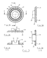
- FIG. 2 shows various views of the housing 2. It has a cup-shaped basic body 20, from which the hollow-cylindrical valve space 21 projects centrally.
- the two connecting pieces 22 and 23 are formed, which are in fluid communication with the interior of the valve chamber 21 via openings 24 and 25, respectively.
- the two connecting pieces 22 and 23 are - relative to the axis of rotation 26 of the control valve - offset by a distance V against each other.
- a latching recess 27 is provided, into which engages a latching lug of the rotary member.
- a radial projection is provided on the outer surface of the valve chamber 21, which serves as a rotation limiting stop 50.
- an edge 28 can be seen in the interior of the valve chamber 21, from which the valve plug (FIG. 4) is in radial sealing engagement with the valve chamber 21.
- Fig. 3 shows the insert 3, which forms a flat annular disc 30 with an opening 31, around which a cylindrical chimney-like projection 32 protrudes.
- the projection 32 has at its free end two opposing recesses 33 with a semicircular base, which engage over the outer sides of the connecting pieces 22 and 23 (of Fig. 2), whereby the insert 3 is held against rotation in the housing 2.
- the annular disc 30 near the outer periphery has a centering collar 34 for centering relative to the housing 2. This centering collar projects from the annular disc 30 in the same direction as the projection 32nd
- Markings or scales 35, 36 and 37 are applied on concentric rings on the upper side of the annular disc 30 visible in FIG. 3a, for example in the form of numerical values for drip rates as a function of the rotational position of the rotary part (4 in FIG radially offset from each other arranged numerical values for different hydrostatic pressures or heights of a container with infusion liquid apply.
- another scale may have letters associated with viscosity values of the liquid.
- Fig. 4 shows the rotary member 4, which also has a cup-shaped base body and a projecting hollow cylindrical valve plug 41.
- the valve plug 41 has on its outer circumference two annular grooves 42 and 43, which are offset from each other in the axial direction.
- the one groove 42 has constant depth and constant cross section, while the other groove 43 has a continuously changing cross section in the circumferential direction, namely a continuously changing depth and sweeps over a limited area in the circumferential direction, which is here for example at 330 °.
- an axial channel 44 is provided, the two grooves 42 and 43 connects with each other.
- the main body 40 has, as best seen in Fig. 4a can be seen, a plurality of windows 45, 46 and 47, which are each offset by 120 ° in the circumferential direction and are arranged offset radially relative to the axis of rotation 26 so that they are not overlap. Adjacent to the windows 45, 46 and 47, recesses 49 are still provided in each case in which a marking is applied, such as e.g. a print indicating different heights, for example 0.5 m, 0.3 m and 0.7 m. Next there is a reading arrow to recognize, which then refers to the marking of the underlying marker of the circular disk 30.
- a marking such as e.g. a print indicating different heights, for example 0.5 m, 0.3 m and 0.7 m.
- the base body 40 has concentric with the Veritilküken 41 a projection 57 with a latching hook, which cooperates with the latching recess 27 of the housing (Fig. 2) and the rotary member with the housing after assembly firmly combines.
- a rotation limiting stop 50 is provided on the valve chamber 21 of the housing 2 above the connecting piece 22, which cooperates with a rotation limiting stop 51 on the rotary member 4.
- the rotation limiting stops 51 and 52 are arranged and dimensioned in the circumferential direction so that the full range of action of the groove 43 can be traversed, so here, for example, the range of 330 °.
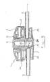
- Fig. 5 shows a cross section through the assembled control valve.
- the assembly takes place so that the first insert 3 is pushed with its projection 32 on the valve chamber 21 of the housing and is aligned in the direction of rotation of the insert 3 so that the recesses 33 engage over the connecting pieces 22 and 23. Due to the different axial height of the connecting piece 22 and 23 and the corresponding different depth of the recesses 33 so that a unique position is fixed in the direction of rotation. Next engages the centering collar 34 in the edge of the housing 2, whereby the insert 3 occupies a unique position.
- the rotary member 4 is used. Its valve plug 41 engages in the opening of the valve chamber 21 of the housing 2. By the mutual engagement of the locking recess 27 and the latching lug 57 of the rotary member takes place an axial locking.
- the groove 42 on the valve plug 41 of the rotary member 4 is then correctly against the opening 24 so that the tube 5 of the connecting piece 23 is in flow communication with the groove 42.
- the groove 42 is connected to the spiral groove 43, whereby a flow connection from the opening 24 to the opening 25 is provided, the effective cross section of the rotational position of the rotary member 4 depends.
- the edge 28 defines the area between the valve chamber 21 and the valve plug 41, from which these two parts sealingly abut each other.
- the part of the Ventikükens 41 from the edge 28, which also carries the two grooves 42 and 43, is made of a material that has a different hardness compared to the material of the valve chamber 21 so that there takes place a good sealing engagement.
- the end face of the valve plug 41 has a distance to the bottom of the recess of the valve chamber 21, so that only the latching connection 27, 57 is decisive for the axial centering between housing and rotary part, if necessary
- a small axial clearance has no influence on the tightness, but on the alignment between the openings 24 and 25 relative to the grooves 42 and 43. Make the openings 24 and 25 slightly wider than the width of the grooves 42 and 43, but also occurs in axial play no change in the flow rate.
- Fig. 6 shows in more detail the grooves 42 and 43 and the channel 44.
- the groove 42 is an annular groove with a constant Cross-section, while the groove 43 is referred to as a spiral groove and extends in the circumferential direction by the angle ⁇ and thereby has decreasing depth to the amount zero. Via the channel 44, the beginning of the groove 43 is always completely supplied with liquid from the channel 42. Depending on the rotational position of the rotary member 4 is a different depth of the groove 43 of the opening 25 opposite and thus determines the flow rate.
- FIG. 7 The insert body 3, which is inserted into the housing 2, contains in the embodiment of FIG. 7, the valve chamber 21, the two connecting pieces 22 and 23 and the annular disc, which is designated here by the reference numeral 3 '.
- This complete insert 3 is then inserted into the housing 2.
- the annular disc 3 'with the printed scales 35, 36 is thus connected to the valve body and the housing 2 was separated from the valve body.
- the housing 2 is thus a separate injection molded part with gripping surfaces 29, which is connected to the insert 3 via a snap connection. Further, in this embodiment, the rotation stopper for the rotary member was placed on the outer edge of the housing.
- the positive connection takes place on the one hand between the rotary member and the valve body and on the other hand between the housing and the valve body.
- the housing 2 has a cup-shaped base body with two lateral recesses 22 'and 23' for receiving the connecting pieces 22 and 23 of the valve body 3, which is inserted from above into the housing.
- From the connecting pieces 22 and 23 are disk-shaped webs 60 and 61 from, each having two locking lugs 62, 63, which can engage in detent openings 64, 65 of the housing 2 and thus firmly anchor the valve body 3 in the housing 2.
- the valve space 21 cross-annular disc 3 'is attached, which carries the scales to be read. In addition, this disc can still be attached via further webs 66 and 67 to the connecting piece.
- an axially projecting rotation stop 68 is provided which cooperates with a counter-abutment 69 (FIG. 10) of the rotating part.
- a circumferential latching lug 70 is attached, which has elastic properties by axial slots 71 and protrudes when inserting the valve plug into the valve chamber 21 from the open bottom 72 and snaps behind the end face located there.
- Fig. 8 shows the housing 2 in plan view from above (Fig. 8a), side views from right and left (Figs. 8b and 8c), bottom view (Fig. 8d), front view (Fig. 8e), in perspective Top view (Fig. 8f), perspective view from below (Fig. 8g) and in longitudinal section the line BB (Fig. 8h) and along the line AA (Fig. 8i).
- Indentations 70 and 71 are provided with grip knobs 72 on the underside of the housing, via which the housing can be gripped well and without slipping with one hand.
- the housing In the interior of the housing webs 73 and 74 are provided for receiving the insert part 3, wherein the webs 73 are adapted to the shape of the connecting pieces 22 and 23 and the webs 62, 63 and 66, 67, so that the insert part 3 is held there form-fitting manner ,
- the web 74 in the housing is annular and serves to center the valve chamber 21.
- a further recess 75 in the bottom of the housing serves to receive the projecting from the valve chamber 21 free end of the valve plug 41st
- FIG. 9 shows the valve body 3 in a view from below (FIG. 9a), side views from left and right (FIGS. 9b and 9c), a front view (FIG. 9d), a perspective view obliquely from below (FIG. 9e). and sectional views taken along line AA of Fig. 9a (Fig. 9f) and taken along line BB (Fig. 9g).
- FIG. 9a and 9b can still be seen that the annular disc 3 'on its outer circumference has a recess 76 for the passage of the stop 68 of the housing 2 (see Fig .. 7). Furthermore, it can be seen that at the upper outer edge of the valve body, a circumferential projection 77 is present, which engages in a recess 81 described below of the rotary member. At the lower end of the valve body 21, a projection 78 is provided (compare Figures 9b, 9e and 9f) which engages in a recess 79 (see Figure 8h) in the web 74 of the housing.
- the projection 78 serves essentially as an injection point during injection molding in order to avoid free jet formation.
- a recess 79 is provided in the web 74 of the housing.
- FIG. 10 shows the rotary part 4 in plan view from above (FIG. 10a), side view (FIG. 10b), bottom view (FIG. 10c), front view (FIG. 10d), a perspective view obliquely from below (FIG ) and a section along the line CC of Fig. 10a (Fig. 10f).
- the rotating part is also pot-shaped here and has two windows 45, 46 for reading the scales on the annular disc 3 '.
- the stop 69 can be seen, which serves as a counter-stop to the stop 68 of the housing 2 (Fig. 7) and causes the rotation limit of the rotary member.
- the locking lug 70 can be seen at the free end of the valve plug 41, with which the rotary member is locked to the valve body 3.
- an axially projecting edge 80 is seen, which extends at a radial distance from the valve plug 41, so that there is an annular space 81 is formed, in which one end of the valve chamber 21 engages with the projection 77, so that the rotary member is guided or stored here opposite the valve body 3.
- FIG. 11 shows the control valve in the assembled state, in side view (FIG. 11 a), top view (FIG. 11 b), in a side view (FIG. 11 c) rotated by 90 °, in two perspective views obliquely from above and obliquely from FIG bottom ( Figure 11d) and a section along the line AA of Figure 11b ( Figure 11e) and a section along the line CC of Figure 11a ( Figure 11f).
- FIGS. 11e and 11f clearly show the assembled state and how the individual components intermesh with one another. Due to the detailed item drawings and the associated description further explanation is not required because the skilled artisan readily recognizes construction and assembly and function of the items. In connection with Fig. 11e, however, it should be mentioned that in the embodiment shown there the two annular grooves 42 and 43 of the valve plug 41 of the first embodiment of FIG. 4 are formed somewhat differently.
- the one groove 42 with constant depth and constant cross-section which can also be referred to as annulus with constant depth and constant cross-section, is not realized here as a groove in the valve plug but by two stages on the valve plug 41 and the valve chamber 21, which are arranged axially offset from one another are, and precisely by the diameter of the opening into the valve chamber a port.
Claims (12)
- Valve pour contrôler le débit dans un procédé de perfusion ou de transfusion, avec- un boîtier (2),- un raccord d'admission et un raccord de sortie (22, 23), qui débouchent dans une chambre de valve creuse cylindrique (21),- une pièce rotative (4), qui présente un élément de base en forme de pot et un boisseau de valve cylindrique (41) qui saille dudit élément de base, est insérable dans la chambre de valve (21) de façon étanche à l'extérieur et présente sur sa circonférence externe au moins une rainure (42, 43) opposée aux raccords (22, 23), laquelle assure une liaison d'écoulement entre lesdits raccords (22, 23) et présente dans le sens de la circonférence une section transversale qui varie,caractérisée par
un disque annulaire (3'), qui recouvre la chambre de valve (21) et qui présente sur sa face orientée vers la pièce rotative (4) plusieurs repères (35, 36, 37) disposés sur des cercles concentriques, et en ce que
la pièce rotative (4) présente plusieurs fenêtres (45, 46, 47), qui sont décalées les unes par rapport aux autres dans le sens de la circonférence et dans le sens radial et qui sont respectivement opposées à l'un des repères (35, 36, 37). - Valve selon la revendication 1, caractérisée en ce que
le disque annulaire (3') présente un collet de centrage annulaire (34), qui saille dans le sens axial et s'engrène dans le boîtier (2). - Valve selon la revendication 1 ou 2, caractérisée en ce que
le disque annulaire (3') présente une saillie cylindrique (32), qui présente sur sa face terminale des encoches (33) opposées l'une à l'autre, lesquelles recouvrent les raccords (22, 23) du boîtier (2). - Valve selon l'une des revendications 1 à 3, caractérisée en ce que
sur la face externe de la chambre de valve (21) est prévue une butée de limitation de rotation (50), qui coopère avec une butée de limitation de rotation (51) prévue sur la pièce rotative (4). - Valve selon l'une des revendications 1 à 4, caractérisée en ce que
la chambre de valve (21) présente sur sa face externe un creux d'arrêt (27), et la pièce rotative (4) présente concentriquement par rapport au boisseau de valve (41) une saillie cylindrique munie d'au moins un taquet d'arrêt (57), lequel s'engrène dans le creux d'arrêt (27). - Valve selon l'une des revendications 1 à 5, caractérisée en ce que
les axes longitudinaux des raccords (22, 23) sont décalés l'un par rapport à l'autre dans le sens axial relativement à l'axe de rotation (26) de la valve. - Valve selon la revendication 6, caractérisée en ce que
le boisseau de valve (41) présente sur sa circonférence externe deux rainures (42, 43), dont l'une est affectée au raccord d'admission et l'autre au raccord de sortie, un canal axial (44) assurant une liaison d'écoulement entre lesdites deux rainures (42, 43). - Valve selon l'une des revendications 1 à 7, caractérisée en ce que
l'intérieur de la chambre de valve (21) présente un gradin (28), à partir duquel une action d'étanchéité a lieu entre la chambre de valve (21) et le boisseau de valve (41). - Valve selon la revendication 1, caractérisée en ce que
le disque annulaire (3'), la chambre de valve (21) et les raccords (22, 23) sont conçus comme un insert (3) insérable dans le boîtier (2). - Valve selon la revendication 9, caractérisée en ce que
sur le bord extérieur supérieur du boîtier (2) est prévue une butée de rotation (68) et sur le fond de la pièce rotative (4) une contre-butée (69). - Valve selon la revendication 10, caractérisée en ce que
l'insert (3) est verrouillable dans des orifices (64, 65) du boîtier (2) par des taquets d'arrêt (62, 63). - Valve selon la revendication 11, caractérisée en ce que
la pièce rotative avec boisseau de valve intégré (41) est verrouillable sur la chambre de valve (21) au moyen d'une saillie d'arrêt (70).
Applications Claiming Priority (2)
| Application Number | Priority Date | Filing Date | Title |
|---|---|---|---|
| DE2002150391 DE10250391B4 (de) | 2002-10-29 | 2002-10-29 | Regelventil zum Einstellen des Volumenstromes bei einem Infusions- oder Transfusionsvorgang |
| DE10250391 | 2002-10-29 |
Publications (2)
| Publication Number | Publication Date |
|---|---|
| EP1415675A1 EP1415675A1 (fr) | 2004-05-06 |
| EP1415675B1 true EP1415675B1 (fr) | 2006-05-17 |
Family
ID=32087273
Family Applications (1)
| Application Number | Title | Priority Date | Filing Date |
|---|---|---|---|
| EP20030024763 Expired - Lifetime EP1415675B1 (fr) | 2002-10-29 | 2003-10-29 | Valve pour contrôler le débit dans une procédé de perfusion où de transfusion |
Country Status (5)
| Country | Link |
|---|---|
| US (1) | US6916010B2 (fr) |
| EP (1) | EP1415675B1 (fr) |
| JP (1) | JP4236558B2 (fr) |
| AT (1) | ATE326247T1 (fr) |
| DE (2) | DE10250391B4 (fr) |
Cited By (1)
| Publication number | Priority date | Publication date | Assignee | Title |
|---|---|---|---|---|
| DE102013212325A1 (de) * | 2013-06-26 | 2014-12-31 | B. Braun Melsungen Ag | Einstellvorrichtung für einen Durchflussregler |
Families Citing this family (25)
| Publication number | Priority date | Publication date | Assignee | Title |
|---|---|---|---|---|
| MXPA03010576A (es) | 2001-05-18 | 2004-05-27 | Deka Products Lp | Equipo de infusion para una bomba de fluido. |
| US8034026B2 (en) | 2001-05-18 | 2011-10-11 | Deka Products Limited Partnership | Infusion pump assembly |
| FR2833175B1 (fr) * | 2001-12-06 | 2004-05-14 | Sobem | Dispositif de controle de debit, a usage medical |
| KR100468222B1 (ko) * | 2004-07-16 | 2005-01-26 | 메인텍 주식회사 | 약액 주입량 조절장치 |
| US7690396B2 (en) * | 2006-07-20 | 2010-04-06 | Baxter International Inc. | Multirate tubing flow restrictor |
| KR100749266B1 (ko) * | 2006-12-29 | 2007-08-13 | 박효남 | 약액 주입장치 |
| WO2009157908A1 (fr) * | 2008-06-27 | 2009-12-30 | Davol, Inc. | Commande de vide endoscopique |
| US9180245B2 (en) | 2008-10-10 | 2015-11-10 | Deka Products Limited Partnership | System and method for administering an infusible fluid |
| US8066672B2 (en) | 2008-10-10 | 2011-11-29 | Deka Products Limited Partnership | Infusion pump assembly with a backup power supply |
| US8262616B2 (en) | 2008-10-10 | 2012-09-11 | Deka Products Limited Partnership | Infusion pump assembly |
| US8016789B2 (en) | 2008-10-10 | 2011-09-13 | Deka Products Limited Partnership | Pump assembly with a removable cover assembly |
| US8267892B2 (en) | 2008-10-10 | 2012-09-18 | Deka Products Limited Partnership | Multi-language / multi-processor infusion pump assembly |
| US8223028B2 (en) | 2008-10-10 | 2012-07-17 | Deka Products Limited Partnership | Occlusion detection system and method |
| US8708376B2 (en) | 2008-10-10 | 2014-04-29 | Deka Products Limited Partnership | Medium connector |
| EP2724739B1 (fr) | 2009-07-30 | 2015-07-01 | Tandem Diabetes Care, Inc. | Système de pompe à perfusion ambulatoire |
| US9180242B2 (en) | 2012-05-17 | 2015-11-10 | Tandem Diabetes Care, Inc. | Methods and devices for multiple fluid transfer |
| US9173998B2 (en) | 2013-03-14 | 2015-11-03 | Tandem Diabetes Care, Inc. | System and method for detecting occlusions in an infusion pump |
| TR201815044T4 (tr) * | 2013-10-07 | 2018-11-21 | Anheuser Busch Inbev Sa | Kontrol elemanı. |
| WO2015073603A1 (fr) | 2013-11-15 | 2015-05-21 | Ivenix, Inc. | Ensemble régulateur d'écoulement de liquide |
| CN104740724A (zh) * | 2013-12-27 | 2015-07-01 | 苏州和林精密科技有限公司 | 医用表盘式精密流量调节器 |
| CN103785082B (zh) * | 2014-02-26 | 2017-09-19 | 上海康德莱企业发展集团医疗器械有限公司 | 一种精密流量调节装置 |
| KR101487754B1 (ko) * | 2014-10-20 | 2015-01-29 | 주식회사한빛엠디 | 수액유량조절기 |
| KR101532613B1 (ko) * | 2014-12-24 | 2015-06-30 | 주식회사한빛엠디 | 정맥내 수액유량 자동 조절장치 |
| KR101650939B1 (ko) * | 2015-05-26 | 2016-08-25 | 마그닉스엔지니어링 (주) | 수액 유량조절기 |
| WO2019117835A2 (fr) * | 2017-08-25 | 2019-06-20 | Medbar Tibbi̇ Malzemeler Turi̇zm Sanayi̇ Ve Ti̇c.A.Ş. | Dispositif de réglage de débit à grande sensibilité constitué de deux parties |
Family Cites Families (10)
| Publication number | Priority date | Publication date | Assignee | Title |
|---|---|---|---|---|
| DE8312029U1 (de) * | 1983-04-23 | 1983-08-18 | B. Braun Melsungen Ag, 3508 Melsungen | Tropfenregelgeraet |
| US5113904A (en) * | 1984-07-13 | 1992-05-19 | Aslanian Jerry L | Flow control device for administration of intravenous fluids |
| IE56756B1 (en) | 1984-07-13 | 1991-12-04 | Master Medical Corp | Flow control device for administration of intravenous fluids |
| US5005604A (en) * | 1984-07-13 | 1991-04-09 | Aslanian Jerry L | Flow control device for administration of intravenous fluids |
| US4750707A (en) * | 1986-10-20 | 1988-06-14 | Perfection Corporation | Angle valve |
| DE4201416A1 (de) | 1992-01-21 | 1993-07-29 | Andreas Mommer | Dosiervorrichtung fuer uebertragungsgeraete der infusions- und transfusionstechnik |
| DE4340191C1 (de) | 1993-11-25 | 1995-02-23 | Matthias Faensen Gmbh & Co Kg | Vorrichtung zur Regulierung des Volumenstromes bei einem Infusions- oder Transfusionsvorgang |
| US6273133B1 (en) * | 1999-10-15 | 2001-08-14 | Baxter International Inc. | Fluid flow rate switching device |
| AU771667B2 (en) * | 1999-11-02 | 2004-04-01 | Fisher & Paykel Appliances Limited | A gas valve |
| JP2002035123A (ja) | 2000-07-19 | 2002-02-05 | Concise:Kk | 点滴用円型計算尺 |
-
2002
- 2002-10-29 DE DE2002150391 patent/DE10250391B4/de not_active Expired - Fee Related
-
2003
- 2003-10-29 JP JP2003368769A patent/JP4236558B2/ja not_active Expired - Fee Related
- 2003-10-29 EP EP20030024763 patent/EP1415675B1/fr not_active Expired - Lifetime
- 2003-10-29 US US10/696,210 patent/US6916010B2/en not_active Expired - Lifetime
- 2003-10-29 DE DE50303351T patent/DE50303351D1/de not_active Expired - Lifetime
- 2003-10-29 AT AT03024763T patent/ATE326247T1/de active
Cited By (1)
| Publication number | Priority date | Publication date | Assignee | Title |
|---|---|---|---|---|
| DE102013212325A1 (de) * | 2013-06-26 | 2014-12-31 | B. Braun Melsungen Ag | Einstellvorrichtung für einen Durchflussregler |
Also Published As
| Publication number | Publication date |
|---|---|
| ATE326247T1 (de) | 2006-06-15 |
| DE10250391A1 (de) | 2004-05-19 |
| US6916010B2 (en) | 2005-07-12 |
| JP4236558B2 (ja) | 2009-03-11 |
| US20040140444A1 (en) | 2004-07-22 |
| JP2004275739A (ja) | 2004-10-07 |
| EP1415675A1 (fr) | 2004-05-06 |
| DE10250391B4 (de) | 2006-05-24 |
| DE50303351D1 (de) | 2006-06-22 |
Similar Documents
| Publication | Publication Date | Title |
|---|---|---|
| EP1415675B1 (fr) | Valve pour contrôler le débit dans une procédé de perfusion où de transfusion | |
| DE60202251T2 (de) | Gerät zur Regelung des Durchflusses medizinischer Flüssigkeiten zu einem Patienten | |
| DE2463442C2 (de) | Dosiervorrichtung | |
| EP2059212B1 (fr) | Connecteur polyvalent pour administration entérale | |
| DE2904127C2 (fr) | ||
| DE3590339C2 (fr) | ||
| DE2702539A1 (de) | Vorrichtung zur abgabe von fluessigkeit in genau vorherbestimmten mengen | |
| DE2933512C2 (de) | Proben-Einspritzventil | |
| EP1248731B1 (fr) | Dispositif d'actionnement verrouillable pour dispositif distributeur d'un contenant a liquide | |
| DE202014001136U1 (de) | Injektionsgerät | |
| EP3102256A1 (fr) | Appareil d'injection | |
| EP0139943A2 (fr) | Dispositif d'étranglement | |
| DE4228565A1 (de) | Ventil mit Voreinstellung | |
| WO2018202424A1 (fr) | Ensemble de chambre compte-gouttes pour un système de perfusion médicale | |
| DE202014001135U1 (de) | Injektionsgerät | |
| DE19812961C2 (de) | Ventilkuppelstück | |
| WO2009049785A1 (fr) | Dispositif d'amenée de liquides médicaux | |
| EP0276416A1 (fr) | Bouche d'écoulement pour robinets orientable dans tous les sens et comprenant un jet d'eau réglable | |
| DE3107413A1 (de) | "dosiervorrichtung fuer infusions- oder transfusionseinrichtungen" | |
| EP0126197B1 (fr) | Dispositif de dosage pour la régulation du débit constant du sang, solutions succédanées du sang et fluides analogues | |
| DE202016102769U1 (de) | Wasserflussregelanordnung einer Gartenspritzpistole und Sperrventil-Anschluss dafür | |
| DE4205508C2 (de) | Dosiervorrichtung | |
| DE19801276C1 (de) | Blutentnahmevorrichtung | |
| EP0552854A1 (fr) | Dispositif de dosage pour système de perfusion | |
| EP1795170B1 (fr) | Dispositif d'administration pour l'alimentation entérale |
Legal Events
| Date | Code | Title | Description |
|---|---|---|---|
| PUAI | Public reference made under article 153(3) epc to a published international application that has entered the european phase |
Free format text: ORIGINAL CODE: 0009012 |
|
| AK | Designated contracting states |
Kind code of ref document: A1 Designated state(s): AT BE BG CH CY CZ DE DK EE ES FI FR GB GR HU IE IT LI LU MC NL PT RO SE SI SK TR |
|
| AX | Request for extension of the european patent |
Extension state: AL LT LV MK |
|
| 17P | Request for examination filed |
Effective date: 20040522 |
|
| AKX | Designation fees paid |
Designated state(s): AT DE GB IT TR |
|
| GRAP | Despatch of communication of intention to grant a patent |
Free format text: ORIGINAL CODE: EPIDOSNIGR1 |
|
| GRAS | Grant fee paid |
Free format text: ORIGINAL CODE: EPIDOSNIGR3 |
|
| GRAA | (expected) grant |
Free format text: ORIGINAL CODE: 0009210 |
|
| AK | Designated contracting states |
Kind code of ref document: B1 Designated state(s): AT DE GB IT TR |
|
| PG25 | Lapsed in a contracting state [announced via postgrant information from national office to epo] |
Ref country code: IT Free format text: LAPSE BECAUSE OF FAILURE TO SUBMIT A TRANSLATION OF THE DESCRIPTION OR TO PAY THE FEE WITHIN THE PRESCRIBED TIME-LIMIT;WARNING: LAPSES OF ITALIAN PATENTS WITH EFFECTIVE DATE BEFORE 2007 MAY HAVE OCCURRED AT ANY TIME BEFORE 2007. THE CORRECT EFFECTIVE DATE MAY BE DIFFERENT FROM THE ONE RECORDED. Effective date: 20060517 |
|
| REG | Reference to a national code |
Ref country code: GB Ref legal event code: FG4D Free format text: NOT ENGLISH |
|
| REF | Corresponds to: |
Ref document number: 50303351 Country of ref document: DE Date of ref document: 20060622 Kind code of ref document: P |
|
| GBT | Gb: translation of ep patent filed (gb section 77(6)(a)/1977) |
Effective date: 20060928 |
|
| PLBE | No opposition filed within time limit |
Free format text: ORIGINAL CODE: 0009261 |
|
| STAA | Information on the status of an ep patent application or granted ep patent |
Free format text: STATUS: NO OPPOSITION FILED WITHIN TIME LIMIT |
|
| 26N | No opposition filed |
Effective date: 20070220 |
|
| PGFP | Annual fee paid to national office [announced via postgrant information from national office to epo] |
Ref country code: DE Payment date: 20181016 Year of fee payment: 16 Ref country code: AT Payment date: 20180925 Year of fee payment: 16 |
|
| PGFP | Annual fee paid to national office [announced via postgrant information from national office to epo] |
Ref country code: MT Payment date: 20181018 Year of fee payment: 6 Ref country code: IT Payment date: 20181018 Year of fee payment: 16 |
|
| REG | Reference to a national code |
Ref country code: DE Ref legal event code: R119 Ref document number: 50303351 Country of ref document: DE |
|
| PG25 | Lapsed in a contracting state [announced via postgrant information from national office to epo] |
Ref country code: DE Free format text: LAPSE BECAUSE OF NON-PAYMENT OF DUE FEES Effective date: 20200501 |
|
| REG | Reference to a national code |
Ref country code: AT Ref legal event code: MM01 Ref document number: 326247 Country of ref document: AT Kind code of ref document: T Effective date: 20191029 |
|
| GBPC | Gb: european patent ceased through non-payment of renewal fee |
Effective date: 20191029 |
|
| PG25 | Lapsed in a contracting state [announced via postgrant information from national office to epo] |
Ref country code: IT Free format text: LAPSE BECAUSE OF NON-PAYMENT OF DUE FEES Effective date: 20191029 Ref country code: GB Free format text: LAPSE BECAUSE OF NON-PAYMENT OF DUE FEES Effective date: 20191029 |
|
| PG25 | Lapsed in a contracting state [announced via postgrant information from national office to epo] |
Ref country code: AT Free format text: LAPSE BECAUSE OF NON-PAYMENT OF DUE FEES Effective date: 20191029 |
|
| PGFP | Annual fee paid to national office [announced via postgrant information from national office to epo] |
Ref country code: TR Payment date: 20221021 Year of fee payment: 20 |