EP1415675B1 - Flow control valve for infusion or transfusion purposes - Google Patents
Flow control valve for infusion or transfusion purposes Download PDFInfo
- Publication number
- EP1415675B1 EP1415675B1 EP20030024763 EP03024763A EP1415675B1 EP 1415675 B1 EP1415675 B1 EP 1415675B1 EP 20030024763 EP20030024763 EP 20030024763 EP 03024763 A EP03024763 A EP 03024763A EP 1415675 B1 EP1415675 B1 EP 1415675B1
- Authority
- EP
- European Patent Office
- Prior art keywords
- housing
- regulating valve
- valve
- valve chamber
- valve according
- Prior art date
- Legal status (The legal status is an assumption and is not a legal conclusion. Google has not performed a legal analysis and makes no representation as to the accuracy of the status listed.)
- Expired - Lifetime
Links
Images


Classifications
-
- A—HUMAN NECESSITIES
- A61—MEDICAL OR VETERINARY SCIENCE; HYGIENE
- A61M—DEVICES FOR INTRODUCING MEDIA INTO, OR ONTO, THE BODY; DEVICES FOR TRANSDUCING BODY MEDIA OR FOR TAKING MEDIA FROM THE BODY; DEVICES FOR PRODUCING OR ENDING SLEEP OR STUPOR
- A61M5/00—Devices for bringing media into the body in a subcutaneous, intra-vascular or intramuscular way; Accessories therefor, e.g. filling or cleaning devices, arm-rests
- A61M5/14—Infusion devices, e.g. infusing by gravity; Blood infusion; Accessories therefor
- A61M5/168—Means for controlling media flow to the body or for metering media to the body, e.g. drip meters, counters ; Monitoring media flow to the body
- A61M5/16877—Adjusting flow; Devices for setting a flow rate
-
- Y—GENERAL TAGGING OF NEW TECHNOLOGICAL DEVELOPMENTS; GENERAL TAGGING OF CROSS-SECTIONAL TECHNOLOGIES SPANNING OVER SEVERAL SECTIONS OF THE IPC; TECHNICAL SUBJECTS COVERED BY FORMER USPC CROSS-REFERENCE ART COLLECTIONS [XRACs] AND DIGESTS
- Y10—TECHNICAL SUBJECTS COVERED BY FORMER USPC
- Y10T—TECHNICAL SUBJECTS COVERED BY FORMER US CLASSIFICATION
- Y10T137/00—Fluid handling
- Y10T137/8158—With indicator, register, recorder, alarm or inspection means
- Y10T137/8225—Position or extent of motion indicator
- Y10T137/8275—Indicator element rigidly carried by the movable element whose position is indicated
- Y10T137/8292—Movable indicator element is a pointer
- Y10T137/8309—Pointer integral with handle
Definitions
- the invention relates to a control valve according to the preamble of claim 1.
- Such a control valve is known from DE 83 12 029 U.
- This control valve has a cup-shaped housing with an inlet and an outlet connection nozzle, which open into a hollow cylindrical valve chamber and a rotary part with a cup-shaped base body and a protruding cylindrical valve plug, which is sealingly inserted into the valve space on the outside and at least one of its outer circumference the connecting piece Having opposite groove which connects the connecting piece in fluid communication with each other and in the circumferential direction a having changing cross-section.
- DE 42 01 416 A1 has a rotary body with two axially offset from one another arranged annular grooves which are connected by an axially extending channel.
- inlet and outlet ports can be offset from each other in the axial direction.
- JP 2002035123 A shows a computing disk for calculating the flow rate in a drip infusion.
- On a flat plate several scales are applied on concentric circles.
- An overlying turntable has according to the scales a plurality of circular segment-shaped windows, through which the scales are visible.
- the flow rate of such control valves depends not only on the effective cross section but also on the hydrostatic pressure.
- a vessel with the infusion liquid is attached to an infusion stand, wherein the vessel is mounted at a predetermined height on the stand.
- a typical height is, for example, 50 cm above the infusion site on the patient. A change of this Height also leads to a change in the drip rate.
- control valve is designed to be easy to assemble and assemble, simply, i. preferably be mediated with one hand and allow precise adjustment of the flow rate.
- the basic principle of the invention is to provide in the lid of the rotary body a plurality of openings or windows which are distributed around the circumference and arranged radially offset from one another. Within the housing and below these windows several markings or scales are provided, namely according to the number of windows on which the flow rate can be read.
- the problem of higher-viscosity liquids can be solved by one of the scales, which for example has only a simple lettering designation, with corresponding reference values assigned to the individual letters and in an accompanying user manual, a handbook etc. corresponding reference values can be assigned.
- Another scale is a standard scale for isotonic saline solutions.
- the control valve which is designated in its entirety by the reference numeral 1, has a housing 2, an insert body 3 and a rotary member 4. About two hose ends 5, the control valve is connected to an unillustrated container for infusion fluid and a blood vessel of the patient.
- the housing 2 has a cup-shaped base body 20, to which a hollow cylindrical, fireplace-like valve chamber 21 is formed, and two lateral connecting pieces 22 and 23 for the tubes (5 in Fig. 1), via openings 24 and 25 with the interior of the cylindrical Valve space 21 are connected.
- the two connection pieces 22 and 23 are arranged offset relative to one another with respect to the longitudinal axis 26 of the valve space 21 (cf., Fig. 2d) and are offset by 180 ° in the circumferential direction.
- On the outer circumference of the cup-shaped base body 20 a plurality of handle nubs 29 are formed, which allow a firm, twist-proof holding by hand.
- annular disc-shaped insert 3 is provided with a central opening 31 which engages over the valve space 21, i. the insert 3 is pushed over the valve space 21.
- the insert 3 is clearly fixed relative to the housing 2, as will be apparent from the later description.
- control valve has a rotary part 4, which, as will be explained in more detail in connection with FIG. 4, has a pot-shaped housing and a hollow-cylindrical valve plug 41 protruding therefrom, which engages in the valve chamber 21.
- the outside of the rotary member 4 has a plurality of windows 45, 46 and 47, which are uniformly distributed in the circumferential direction and which are arranged offset in the radial direction to each other.
- Each window 45, 46 and 47 is associated with a marker 35, 36, 37 so that the corresponding marker is readable by the associated window.
- the control valve 1 according to the first embodiment is therefore in principle only three parts 2, 3, 4, which are for example made of plastic by injection molding.
- the three parts are very easy to assemble. It is only the insert 3 is placed and then the rotary member 4 pushed over it and locked by a snap closure still described below.
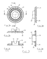
- FIG. 2 shows various views of the housing 2. It has a cup-shaped basic body 20, from which the hollow-cylindrical valve space 21 projects centrally.
- the two connecting pieces 22 and 23 are formed, which are in fluid communication with the interior of the valve chamber 21 via openings 24 and 25, respectively.
- the two connecting pieces 22 and 23 are - relative to the axis of rotation 26 of the control valve - offset by a distance V against each other.
- a latching recess 27 is provided, into which engages a latching lug of the rotary member.
- a radial projection is provided on the outer surface of the valve chamber 21, which serves as a rotation limiting stop 50.
- an edge 28 can be seen in the interior of the valve chamber 21, from which the valve plug (FIG. 4) is in radial sealing engagement with the valve chamber 21.
- Fig. 3 shows the insert 3, which forms a flat annular disc 30 with an opening 31, around which a cylindrical chimney-like projection 32 protrudes.
- the projection 32 has at its free end two opposing recesses 33 with a semicircular base, which engage over the outer sides of the connecting pieces 22 and 23 (of Fig. 2), whereby the insert 3 is held against rotation in the housing 2.
- the annular disc 30 near the outer periphery has a centering collar 34 for centering relative to the housing 2. This centering collar projects from the annular disc 30 in the same direction as the projection 32nd
- Markings or scales 35, 36 and 37 are applied on concentric rings on the upper side of the annular disc 30 visible in FIG. 3a, for example in the form of numerical values for drip rates as a function of the rotational position of the rotary part (4 in FIG radially offset from each other arranged numerical values for different hydrostatic pressures or heights of a container with infusion liquid apply.
- another scale may have letters associated with viscosity values of the liquid.
- Fig. 4 shows the rotary member 4, which also has a cup-shaped base body and a projecting hollow cylindrical valve plug 41.
- the valve plug 41 has on its outer circumference two annular grooves 42 and 43, which are offset from each other in the axial direction.
- the one groove 42 has constant depth and constant cross section, while the other groove 43 has a continuously changing cross section in the circumferential direction, namely a continuously changing depth and sweeps over a limited area in the circumferential direction, which is here for example at 330 °.
- an axial channel 44 is provided, the two grooves 42 and 43 connects with each other.
- the main body 40 has, as best seen in Fig. 4a can be seen, a plurality of windows 45, 46 and 47, which are each offset by 120 ° in the circumferential direction and are arranged offset radially relative to the axis of rotation 26 so that they are not overlap. Adjacent to the windows 45, 46 and 47, recesses 49 are still provided in each case in which a marking is applied, such as e.g. a print indicating different heights, for example 0.5 m, 0.3 m and 0.7 m. Next there is a reading arrow to recognize, which then refers to the marking of the underlying marker of the circular disk 30.
- a marking such as e.g. a print indicating different heights, for example 0.5 m, 0.3 m and 0.7 m.
- the base body 40 has concentric with the Veritilküken 41 a projection 57 with a latching hook, which cooperates with the latching recess 27 of the housing (Fig. 2) and the rotary member with the housing after assembly firmly combines.
- a rotation limiting stop 50 is provided on the valve chamber 21 of the housing 2 above the connecting piece 22, which cooperates with a rotation limiting stop 51 on the rotary member 4.
- the rotation limiting stops 51 and 52 are arranged and dimensioned in the circumferential direction so that the full range of action of the groove 43 can be traversed, so here, for example, the range of 330 °.
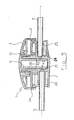
- Fig. 5 shows a cross section through the assembled control valve.
- the assembly takes place so that the first insert 3 is pushed with its projection 32 on the valve chamber 21 of the housing and is aligned in the direction of rotation of the insert 3 so that the recesses 33 engage over the connecting pieces 22 and 23. Due to the different axial height of the connecting piece 22 and 23 and the corresponding different depth of the recesses 33 so that a unique position is fixed in the direction of rotation. Next engages the centering collar 34 in the edge of the housing 2, whereby the insert 3 occupies a unique position.
- the rotary member 4 is used. Its valve plug 41 engages in the opening of the valve chamber 21 of the housing 2. By the mutual engagement of the locking recess 27 and the latching lug 57 of the rotary member takes place an axial locking.
- the groove 42 on the valve plug 41 of the rotary member 4 is then correctly against the opening 24 so that the tube 5 of the connecting piece 23 is in flow communication with the groove 42.
- the groove 42 is connected to the spiral groove 43, whereby a flow connection from the opening 24 to the opening 25 is provided, the effective cross section of the rotational position of the rotary member 4 depends.
- the edge 28 defines the area between the valve chamber 21 and the valve plug 41, from which these two parts sealingly abut each other.
- the part of the Ventikükens 41 from the edge 28, which also carries the two grooves 42 and 43, is made of a material that has a different hardness compared to the material of the valve chamber 21 so that there takes place a good sealing engagement.
- the end face of the valve plug 41 has a distance to the bottom of the recess of the valve chamber 21, so that only the latching connection 27, 57 is decisive for the axial centering between housing and rotary part, if necessary
- a small axial clearance has no influence on the tightness, but on the alignment between the openings 24 and 25 relative to the grooves 42 and 43. Make the openings 24 and 25 slightly wider than the width of the grooves 42 and 43, but also occurs in axial play no change in the flow rate.
- Fig. 6 shows in more detail the grooves 42 and 43 and the channel 44.
- the groove 42 is an annular groove with a constant Cross-section, while the groove 43 is referred to as a spiral groove and extends in the circumferential direction by the angle ⁇ and thereby has decreasing depth to the amount zero. Via the channel 44, the beginning of the groove 43 is always completely supplied with liquid from the channel 42. Depending on the rotational position of the rotary member 4 is a different depth of the groove 43 of the opening 25 opposite and thus determines the flow rate.
- FIG. 7 The insert body 3, which is inserted into the housing 2, contains in the embodiment of FIG. 7, the valve chamber 21, the two connecting pieces 22 and 23 and the annular disc, which is designated here by the reference numeral 3 '.
- This complete insert 3 is then inserted into the housing 2.
- the annular disc 3 'with the printed scales 35, 36 is thus connected to the valve body and the housing 2 was separated from the valve body.
- the housing 2 is thus a separate injection molded part with gripping surfaces 29, which is connected to the insert 3 via a snap connection. Further, in this embodiment, the rotation stopper for the rotary member was placed on the outer edge of the housing.
- the positive connection takes place on the one hand between the rotary member and the valve body and on the other hand between the housing and the valve body.
- the housing 2 has a cup-shaped base body with two lateral recesses 22 'and 23' for receiving the connecting pieces 22 and 23 of the valve body 3, which is inserted from above into the housing.
- From the connecting pieces 22 and 23 are disk-shaped webs 60 and 61 from, each having two locking lugs 62, 63, which can engage in detent openings 64, 65 of the housing 2 and thus firmly anchor the valve body 3 in the housing 2.
- the valve space 21 cross-annular disc 3 'is attached, which carries the scales to be read. In addition, this disc can still be attached via further webs 66 and 67 to the connecting piece.
- an axially projecting rotation stop 68 is provided which cooperates with a counter-abutment 69 (FIG. 10) of the rotating part.
- a circumferential latching lug 70 is attached, which has elastic properties by axial slots 71 and protrudes when inserting the valve plug into the valve chamber 21 from the open bottom 72 and snaps behind the end face located there.
- Fig. 8 shows the housing 2 in plan view from above (Fig. 8a), side views from right and left (Figs. 8b and 8c), bottom view (Fig. 8d), front view (Fig. 8e), in perspective Top view (Fig. 8f), perspective view from below (Fig. 8g) and in longitudinal section the line BB (Fig. 8h) and along the line AA (Fig. 8i).
- Indentations 70 and 71 are provided with grip knobs 72 on the underside of the housing, via which the housing can be gripped well and without slipping with one hand.
- the housing In the interior of the housing webs 73 and 74 are provided for receiving the insert part 3, wherein the webs 73 are adapted to the shape of the connecting pieces 22 and 23 and the webs 62, 63 and 66, 67, so that the insert part 3 is held there form-fitting manner ,
- the web 74 in the housing is annular and serves to center the valve chamber 21.
- a further recess 75 in the bottom of the housing serves to receive the projecting from the valve chamber 21 free end of the valve plug 41st
- FIG. 9 shows the valve body 3 in a view from below (FIG. 9a), side views from left and right (FIGS. 9b and 9c), a front view (FIG. 9d), a perspective view obliquely from below (FIG. 9e). and sectional views taken along line AA of Fig. 9a (Fig. 9f) and taken along line BB (Fig. 9g).
- FIG. 9a and 9b can still be seen that the annular disc 3 'on its outer circumference has a recess 76 for the passage of the stop 68 of the housing 2 (see Fig .. 7). Furthermore, it can be seen that at the upper outer edge of the valve body, a circumferential projection 77 is present, which engages in a recess 81 described below of the rotary member. At the lower end of the valve body 21, a projection 78 is provided (compare Figures 9b, 9e and 9f) which engages in a recess 79 (see Figure 8h) in the web 74 of the housing.
- the projection 78 serves essentially as an injection point during injection molding in order to avoid free jet formation.
- a recess 79 is provided in the web 74 of the housing.
- FIG. 10 shows the rotary part 4 in plan view from above (FIG. 10a), side view (FIG. 10b), bottom view (FIG. 10c), front view (FIG. 10d), a perspective view obliquely from below (FIG ) and a section along the line CC of Fig. 10a (Fig. 10f).
- the rotating part is also pot-shaped here and has two windows 45, 46 for reading the scales on the annular disc 3 '.
- the stop 69 can be seen, which serves as a counter-stop to the stop 68 of the housing 2 (Fig. 7) and causes the rotation limit of the rotary member.
- the locking lug 70 can be seen at the free end of the valve plug 41, with which the rotary member is locked to the valve body 3.
- an axially projecting edge 80 is seen, which extends at a radial distance from the valve plug 41, so that there is an annular space 81 is formed, in which one end of the valve chamber 21 engages with the projection 77, so that the rotary member is guided or stored here opposite the valve body 3.
- FIG. 11 shows the control valve in the assembled state, in side view (FIG. 11 a), top view (FIG. 11 b), in a side view (FIG. 11 c) rotated by 90 °, in two perspective views obliquely from above and obliquely from FIG bottom ( Figure 11d) and a section along the line AA of Figure 11b ( Figure 11e) and a section along the line CC of Figure 11a ( Figure 11f).
- FIGS. 11e and 11f clearly show the assembled state and how the individual components intermesh with one another. Due to the detailed item drawings and the associated description further explanation is not required because the skilled artisan readily recognizes construction and assembly and function of the items. In connection with Fig. 11e, however, it should be mentioned that in the embodiment shown there the two annular grooves 42 and 43 of the valve plug 41 of the first embodiment of FIG. 4 are formed somewhat differently.
- the one groove 42 with constant depth and constant cross-section which can also be referred to as annulus with constant depth and constant cross-section, is not realized here as a groove in the valve plug but by two stages on the valve plug 41 and the valve chamber 21, which are arranged axially offset from one another are, and precisely by the diameter of the opening into the valve chamber a port.
Abstract
Description
Die Erfindung bezieht sich auf ein Regelventil gemäß dem Oberbegriff des Patentanspruches 1.The invention relates to a control valve according to the preamble of
Ein solches Regelventil ist aus der DE 83 12 029 U bekannt. Dieses Regelventil hat ein topfförmiges Gehäuse mit einem Einlaß- und einem Auslaßanschlußstutzen, die in einen hohlzylindrischen Ventilraum münden und ein Drehteil mit einem topfförmigen Grundkörper und einem davon abstehenden zylindrischen Ventilküken, das außenseitig dichtend in den Ventilraum einsetzbar ist und an seinem Außenumfang mindestens eine den Anschlußstutzen gegenüberliegenden Nut aufweist, die die Anschlußstutzen strömungsmäßig miteinander verbindet und in Umfangsrichtung einen sich ändernden Querschnitt aufweist.Such a control valve is known from DE 83 12 029 U. This control valve has a cup-shaped housing with an inlet and an outlet connection nozzle, which open into a hollow cylindrical valve chamber and a rotary part with a cup-shaped base body and a protruding cylindrical valve plug, which is sealingly inserted into the valve space on the outside and at least one of its outer circumference the connecting piece Having opposite groove which connects the connecting piece in fluid communication with each other and in the circumferential direction a having changing cross-section.
Ein ähnliches Regelventil ist in der DE 43 40 191 C1 beschrieben. Zur Drehbegrenzung des Drehteiles sind dort am Boden des topfförmigen Gehäuses sowie am Boden des topfförmigen Drehkörpers komplementäre Anschläge für eine Drehbegrenzung vorgesehen.A similar control valve is described in
Die DE 42 01 416 A1 hat einen Drehkörper mit zwei in Axialrichtung gegeneinander versetzt angeordnete Ringnuten, die durch einen axial verlaufenden Kanal verbunden sind. Damit können Einlaß- und Auslaßanschluß in Axialrichtung gegeneinander versetzt sein.DE 42 01 416 A1 has a rotary body with two axially offset from one another arranged annular grooves which are connected by an axially extending channel. Thus, inlet and outlet ports can be offset from each other in the axial direction.
Ein weiteres ähnliches Regelventil ist in der DE 35 90 339 C2 beschrieben, wobei dort ein zylinderförmiger Drehkörper an seiner Stirnseite eine sich in Umfangsrichtung verbreiternde Nut hat und Einlaß- und Auslaßanschlüsse in den Boden eines topfförmigen Gehäuses münden. Voraussetzung für eine einwandfreie Funktion ist dort ein dichtender Kontakt zwischen Boden des Gehäuses und Stirnfläche des Drehkörpers, da ansonsten eine Strömungsverbindung zwischen Einlaß- und Auslaßanschluß außerhalb der Nut möglich ist.Another similar control valve is described in
Die JP 2002035123 A zeigt eine Rechenscheibe zur Berechnung der Durchflußrate bei einer Tropfinfusion. Auf einer ebenen Platte sind mehrere Skalen auf konzentrischen Kreisen aufgebracht. Eine darüberliegende Drehscheibe hat entsprechend den Skalen mehrere kreissegmentförmige Fenster, durch welche hindurch die Skalen sichtbar sind.JP 2002035123 A shows a computing disk for calculating the flow rate in a drip infusion. On a flat plate several scales are applied on concentric circles. An overlying turntable has according to the scales a plurality of circular segment-shaped windows, through which the scales are visible.
Die Durchflußrate bei solchen Regelventilen hängt nicht nur vom wirksamen Querschnitt sondern auch vom hydrostatischen Druck ab. Üblicherweise wird ein Gefäß mit der Infusionsflüssigkeit an ein Infusionsständer befestigt, wobei das Gefäß in vorgegebener Höhe an dem Ständer angebracht wird. Eine übliche Höhe ist beispielsweise 50 cm oberhalb der Infusionsstelle am Patienten. Eine Veränderung dieser Höhe führt auch zu einer Veränderung der Tropfrate.The flow rate of such control valves depends not only on the effective cross section but also on the hydrostatic pressure. Usually, a vessel with the infusion liquid is attached to an infusion stand, wherein the vessel is mounted at a predetermined height on the stand. A typical height is, for example, 50 cm above the infusion site on the patient. A change of this Height also leads to a change in the drip rate.
Wünschenswert wäre es für das Klinikpersonal eine Aussage über die Tropfrate in Abhängigkeit vom hydrostatischen Druck und in Abhängigkeit von der Drehstellung des Drehkörpers zu erhalten, und zwar so, daß die Auswirkung einer Änderung des hydrostatischen Druckes, also der Höhe des Behälters, schon vor Veränderung der Höhe abgeschätzt werden kann. Daneben soll das Regelventil einfach aufgebaut und zu montieren, einfach, d.h. möglichst mit einer Hand medienbar sein und eine präzise Einstellung der Durchflußrate ermöglichen.It would be desirable for the hospital staff to obtain information about the rate of dripping as a function of the hydrostatic pressure and in dependence on the rotational position of the rotating body, in such a way that the effect of a change in the hydrostatic pressure, ie the height of the container, before changing the Height can be estimated. In addition, the control valve is designed to be easy to assemble and assemble, simply, i. preferably be mediated with one hand and allow precise adjustment of the flow rate.
Ebenso wird bei bekannten Durchflußreglern häufig beanstandet, daß nur die Flußraten für eine niederviskose Kochsalzlösung angezeigt werden. Bei Verwendung höherviskoser Flüssigkeiten sind die üblichen Skalen nicht anwendbar, ja sogar irreführend und können zu Fehlinterpretationen führen. Demgegenüber wäre eine Skala zur Angabe der Flußrate höherviskoser Flüssigkeiten für den Anwender von Vorteil.Likewise, in known flow regulators it is often objected that only the flow rates for a low-viscosity saline solution are displayed. When using higher-viscosity liquids, the usual scales are not applicable, and even misleading and can lead to misinterpretation. In contrast, a scale for indicating the flow rate of higher viscosity liquids would be beneficial to the user.
Diese Aufgabe wird durch die im Patentanspruch 1 angegebenen Merkmale gelöst. Vorteilhafte Ausgestaltungen und Weiterbildungen der Erfindung sind den Unteransprüchen zu entnehmen.This object is achieved by the features specified in
Das Grundprinzip der Erfindung liegt darin, im Deckel des Drehkörpers mehrere Öffnungen bzw. Fenster vorzusehen, die um den Umfang verteilt und radial gegeneinander versetzt angeordnet sind. Innerhalb des Gehäuses und dabei unterhalb dieser Fenster sind mehrere Markierungen bzw. Skalen vorgesehen, nämlich entsprechend der Anzahl der Fenster, auf denen die Durchflußrate ablesbar ist.The basic principle of the invention is to provide in the lid of the rotary body a plurality of openings or windows which are distributed around the circumference and arranged radially offset from one another. Within the housing and below these windows several markings or scales are provided, namely according to the number of windows on which the flow rate can be read.
Das Problem höherviskoser Flüssigkeiten läßt sich durch eine der Skalen lösen, die beispielsweise lediglich eine einfache Kennzeichnung mit Buchstaben hat, wobei entsprechende Referenzwerte den einzelnen Buchstaben zugeordnet sind und in einer beigefügten Bedienungsanleitung, einem Handbuch o.ä. entsprechenden Referenzwerten zugeordnet werden können. Eine andere Skala ist eine Standardskala für isotonische Kochsalzlösungen.The problem of higher-viscosity liquids can be solved by one of the scales, which for example has only a simple lettering designation, with corresponding reference values assigned to the individual letters and in an accompanying user manual, a handbook etc. corresponding reference values can be assigned. Another scale is a standard scale for isotonic saline solutions.
Im folgenden wird die Erfindung anhand eines Ausführungsbeispieles im Zusammenhang mit der Zeichnung ausführlicher erläutert. Es zeigt:
- Fig. 1
- eine Explosionszeichnung eines Regelventiles nach der Erfindung;
- Fig. 2
- das Gehäuse des Regelventiles in Ansicht von unten (Fig. 2a), zwei Seitenansichten (Fig. 2b und 2c) sowie zwei Schnittansichten (Fig. 2d und 2e);
- Fig. 3
- verschiedene Ansichten eines Einsatzkörpers in Draufsicht (Fig. 3a), zwei Seitenansichten (Fig. 3b und 3d) und zwei Schnittansichten (Fig. 3c und 3e);
- Fig. 4
- verschiedene Ansichten des Drehkörpers, nämlich eine Draufsicht (Fig. 4a), zwei Seitenansichten (Fig. 4b und 4d) sowie zwei Schnittansichten (Fig. 4c und 4e);
- Fig. 5
- einen Querschnitt des Regelventiles in zusammengebautem Zustand;
- Fig. 6
- zwei Schnitte durch den Drehkörper im Bereich der Ringnut als Querschnitt (Fig. 6a) und Längsschnitt (Fig. 6b);
- Fig. 7
- eine Explosionszeichnung eines Regelventiles nach einem zweiten Ausführungsbeispiel der Erfindung;
- Fig. 8
- verschiedene Darstellungen und Ansichten des Gehäuses des Ausführungsbeispieles der Fig. 7;
- Fig. 9
- verschiedene Darstellungen und Ansichten des Ventilkörpers des Ausführungsbeispieles der Fig. 7;
- Fig. 10
- verschiedene Darstellungen und Ansichten des Drehteiles des Ausführungsbeispieles der Fig. 7; und
- Fig. 11
- verschiedene Ansichten und Darstellungen des zusammengesetzten Regelventils des Ausführungsbeispieles der Fig. 7.
- Fig. 1
- an exploded view of a control valve according to the invention;
- Fig. 2
- the housing of the control valve in bottom view (Figure 2a), two side views (Figures 2b and 2c) and two sectional views (Figures 2d and 2e).
- Fig. 3
- different views of an insert body in plan view (Figure 3a), two side views (Figures 3b and 3d) and two sectional views (Figures 3c and 3e).
- Fig. 4
- different views of the rotating body, namely a plan view (Figure 4a), two side views (Figures 4b and 4d) and two sectional views (Figures 4c and 4e).
- Fig. 5
- a cross section of the control valve in the assembled state;
- Fig. 6
- two sections through the rotary body in the region of the annular groove as a cross section (Fig. 6a) and longitudinal section (Fig. 6b);
- Fig. 7
- an exploded view of a control valve according to a second embodiment of the invention;
- Fig. 8
- various views and views of the housing of the embodiment of FIG. 7;
- Fig. 9
- various views and views of the valve body of the embodiment of FIG. 7;
- Fig. 10
- various views and views of the rotary member of the embodiment of FIG. 7; and
- Fig. 11
- various views and representations of the composite control valve of the embodiment of FIG. 7th
Zunächst sei auf Fig. 1 Bezug genommen. Das Regelventil, das in seiner Gesamtheit mit dem Bezugszeichen 1 bezeichnet ist, hat ein Gehäuse 2, einen Einsatzkörper 3 und ein Drehteil 4. Über zwei Schlauchenden 5 wird das Regelventil mit einem nichtdargestellten Behälter für Infusionsflüssigkeit und einem Blutgefäß des Patienten verbunden.First, reference is made to FIG. 1. The control valve, which is designated in its entirety by the
Das Gehäuse 2 hat einen topfförmigen Grundkörper 20, an den ein hohlzylindrischer, kaminartiger Ventilraum 21 angeformt ist, sowie zwei seitliche Anschlußstutzen 22 und 23 für die Schläuche (5 in Fig. 1), die über Öffnungen 24 bzw. 25 mit dem Innenraum des zylindrischen Ventilraumes 21 verbunden sind. Die beiden Anschlußstutzen 22 und 23 sind bezogen auf die Längsachse 26 des Ventilraumes 21 gegeneinander versetzt angeordnet (vgl. Fig. 2d) und liegen sich in Umfangsrichtung um 180° versetzt gegenüber. Am Außenumfang des topfförmigen Grundkörpers 20 sind mehrere Griffnoppen 29 angeformt, die ein festes, verdrehsicheres Halten mit der Hand gestatten.The
Weiter ist ein ringscheibenförmiger Einsatz 3 mit einer mittigen Öffnung 31 vorgesehen, die den Ventilraum 21 übergreift, d.h. der Einsatz 3 wird über den Ventilraum 21 geschoben. An seiner dem Gehäuse abgewandten Oberseite sind auf den Einsatz 3 auf mehreren konzentrischen Kreisbahnen Markierungen 35, 36 und 37 aufgebracht. Der Einsatz 3 ist gegenüber dem Gehäuse 2 eindeutig fixiert, wie noch aus der späteren Beschreibung hervorgeht.Further, an annular disc-shaped
Schließlich hat das Regelventil ein Drehteil 4, welches, wie im Zusammenhang mit Fig. 4 noch ausführlicher erläutert wird, ein topfförmiges Gehäuse und ein davon abstehendes hohlzylindrisches Ventilküken 41 aufweist, das in den Ventilraum 21 eingreift. Die Außenseite des Drehteiles 4 hat mehrere Fenster 45, 46 und 47, die in Umfangsrichtung gleichmäßig verteilt sind und die in Radialrichtung jeweils zueinander versetzt angeordnet sind. Jedes Fenster 45, 46 und 47 ist einer Markierung 35, 36, 37 zugeordnet, so daß die entsprechende Markierung durch das zugeordnete Fenster ablesbar ist.Finally, the control valve has a
Das Regelventil 1 nach dem ersten Ausführungsbeispiel besteht im Prinzip also nur aus drei Teilen 2, 3, 4, die beispielsweise aus Kunststoff im Spritzgußverfahren hergestellt werden. Die drei Teile sind sehr einfach zu montieren. Es wird lediglich der Einsatz 3 aufgesetzt und dann das Drehteil 4 darüber geschoben und durch einen weiter unten noch beschriebenen Schnappverschluß verriegelt.The
Fig. 2 zeigt verschiedene Ansichten des Gehäuses 2. es hat einen topfförmigen Grundkörper 20, von dem mittig der hohlzylindrische Ventilraum 21 absteht. An die Außenseite des Ventilraumes 21 sind die beiden Anschlußstutzen 22 und 23 angeformt, die über Öffnungen 24 bzw. 25 in Strömungsverbindung mit dem Innenraum des Ventilraumes 21 stehen. Die beiden Anschlußstutzen 22 und 23 sind - bezogen auf die Drehachse 26 des Regelventiles - um eine Strecke V gegeneinander versetzt. An der Außenseite des freien Endes des Ventilraumes 21 ist eine Rastvertiefung 27 vorgesehen, in die eine Rastnase des Drehteiles eingreift. Im Übergangsbereich zwischen dem einen Anschlußstutzen 22 und dem Ventilraum 21 ist an der Außenfläche des Ventilraumes 21 ein radialer Vorsprung vorgesehen, der als Drehbegrenzungsanschlag 50 dient.FIG. 2 shows various views of the
In den Schnittdarstellungen der Fig. 2b und 2d ist im Innenraum des Ventilraumes 21 eine Kante 28 zu erkennen, ab der das Ventilküken (Fig. 4) in radial dichtendem Eingriff mit dem Ventilraum 21 steht.In the sectional views of FIGS. 2b and 2d, an
Fig. 3 zeigt den Einsatz 3, der eine ebene Kreisringscheibe 30 mit einer Öffnung 31 bildet, rings um die ein zylindrischer kaminartiger Vorsprung 32 absteht. Der Vorsprung 32 hat an seinem freien Ende zwei gegenüberliegende Ausnehmungen 33 mit halbkreisförmigem Grund, die die Außenseiten der Anschlußstutzen 22 und 23 (aus Fig. 2) übergreifen, womit der Einsatz 3 verdrehsicher im Gehäuse 2 gehalten ist. Weiter hat die Kreisringscheibe 30 nahe dem Außenumfang einen Zentrierbund 34 zur Zentrierung gegenüber dem Gehäuse 2. Dieser Zentrierbund steht von der Kreisringscheibe 30 in derselben Richtung ab wie der Vorsprung 32.Fig. 3 shows the
Auf der in Fig. 3a sichtbaren Oberseite der Kreisringscheibe 30 sind auf konzentrischen Ringen Markierungen bzw. Skalen 35, 36 und 37 aufgebracht, beispielsweise in Form von Zahlenwerten für Tropfraten in Abhängigkeit von der Drehstellung des Drehteiles (4 in Fig. 1), wobei die radial gegeneinander versetzt angeordneten Zahlenwerte für unterschiedliche hydrostatische Drücke bzw. Höhen eines Behälters mit Infusionsflüssigkeit gelten. Eine andere Skala kann beispielsweise Buchstaben aufweisen, die Viskositätswerten der Flüssigkeit zugeordnet sind.Markings or scales 35, 36 and 37 are applied on concentric rings on the upper side of the
Aus den Figuren 3b, 3c und 3e ist zu erkennen, daß die einander gegenüberliegenden Ausnehmungen 33 unterschiedliche Tiefe haben, nämlich entsprechend dem axialen Versatz V der Anschlußstutzen 22 und 23 (Fig. 2).It can be seen from FIGS. 3b, 3c and 3e that the mutually
Fig. 4 zeigt das Drehteil 4, das ebenfalls einen topfförmigen Grundkörper und ein davon abstehendes hohlzylindrisches Ventilküken 41 aufweist. Das Ventilküken 41 hat an seinem Außenumfang zwei Ringnuten 42 und 43, die in Axialrichtung gegeneinander versetzt sind. Die eine Nut 42 hat konstante Tiefe und konstanten Querschnitt, während die andere Nut 43 in Umfangsrichtung einen sich stetig ändernden Querschnitt, nämlich eine sich stetig ändernde Tiefe aufweist und in Umfangsrichtung einen begrenzten Bereich überstreicht, der hier beispielsweise bei 330° liegt. Am Anfang der Nut 43, nämlich dort, wo diese ihre größte Tiefe hat, ist ein axialer Kanal 44 vorgesehen, der die beiden Nuten 42 und 43 miteinander verbindet.Fig. 4 shows the
Der Grundkörper 40 hat, wie am besten aus Fig. 4a zu erkennen ist, mehrere Fenster 45, 46 und 47, die jeweils um 120° in Umfangsrichtung versetzt angeordnet sind und gegenüber der Drehachse 26 auch radial versetzt angeordnet sind, so daß sie sich nicht überlappen. Benachbart zu den Fenstern 45, 46 und 47 sind jeweils noch Vertiefungen 49 vorgesehen, in denen eine Markierung aufgebracht ist, wie z.B. eine Bedruckung, die unterschiedliche Höhen angibt, beispielsweise 0,5 m, 0,3 m und 0,7 m. Weiter ist dort ein Ablesepfeil zu erkennen, der dann auf die Markierung der darunterliegenden Markierung der Kreisringscheibe 30 verweist.The
Wie am besten aus Fig. 4e zu erkennen ist, hat der Grundkörper 40 konzentrisch zu dem Veritilküken 41 einen Vorsprung 57 mit einem Rasthaken, der mit der Rastvertiefung 27 des Gehäuses (Fig. 2) zusammenwirkt und das Drehteil mit dem Gehäuse nach der Montage fest verbindet.As best seen in Fig. 4e, the
Zur Drehbegrenzung ist am Ventilraum 21 des Gehäuses 2 oberhalb des Anschlußstutzens 22 ein Drehbegrenzungsanschlag 50 vorgesehen, der mit einem Drehbegrenzungsanschlag 51 am Drehteil 4 zusammenwirkt. Die Drehbegrenzungsanschläge 51 und 52 sind in Umfangsrichtung so angeordnet und dimensioniert, daß der volle Wirkungsbereich der Nut 43 durchlaufen werden kann, also hier beispielsweise der Bereich von 330°.For rotation limitation, a
Fig. 5 zeigt einen Querschnitt durch das zusammengebaute Regelventil. Der Zusammenbau erfolgt so, daß als erstes der Einsatz 3 mit seinem Vorsprung 32 über den Ventilraum 21 des Gehäuses geschoben wird und dabei in Drehrichtung der Einsatz 3 so ausgerichtet wird, daß die Ausnehmungen 33 über die Anschlußstutzen 22 und 23 greifen. Aufgrund der unterschiedlichen axialen Höhe der Anschlußstutzen 22 und 23 und der entsprechenden unterschiedlichen Tiefe der Ausnehmungen 33 ist damit eine eindeutige Lage in Drehrichtung fixiert. Weiter greift der Zentrierbund 34 in den Rand des Gehäuses 2, womit der Einsatz 3 eine eindeutige Lage einnimmt.Fig. 5 shows a cross section through the assembled control valve. The assembly takes place so that the
Sodann wird das Drehteil 4 eingesetzt. Sein Ventilküken 41 greift dabei in die Öffnung des Ventilraumes 21 des Gehäuses 2. Durch den wechselseitigen Eingriff der Rastvertiefung 27 und der Rastnase 57 des Drehteiles erfolgt eine axiale Verriegelung. Die Nut 42 am Ventilküken 41 des Drehteiles 4 liegt dann korrekt gegenüber der Öffnung 24, so daß der Schlauch 5 des Anschlußstutzens 23 mit der Nut 42 in Strömungsverbindung steht. Durch den Kanal 44 ist die Nut 42 mit der Spiralnut 43 verbunden, womit eine Strömungsverbindung von der Öffnung 24 zur Öffnung 25 geschaffen ist, deren wirksamer Querschnitt von der Drehstellung des Drehteiles 4 abhängt.Then, the
Die Kante 28 definiert den Bereich zwischen dem Ventilraum 21 und dem Ventilküken 41, ab dem diesen beiden Teile dichtend aneinander liegen. Der Teil des Ventikükens 41 ab der Kante 28, der auch die beiden Nuten 42 und 43 trägt, ist dabei aus einem Material, das gegenüber dem Material des Ventilraumes 21 eine unterschiedliche Härte hat, damit dort ein guter dichtender Eingriff stattfindet. Die Dichtung wirkt alleine in der Mantelfläche des Ventilkükens 41. Die Stirnseite des Ventilkükens 41 hat dabei einen Abstand zum Boden der Ausnehmung des Ventilraumes 21, so daß auch für die axiale Zentrierung zwischen Gehäuse und Drehteil nur die Rastverbindung 27, 57 maßgeblich ist, ggf. zusammen mit einem Anschlag an der Stirnfläche des Ventilraumes 21. Ein geringes axiales Spiel hat auf die Dichtigkeit keinen Einfluß, wohl aber auf die Ausrichtung zwischen den Öffnungen 24 und 25 gegenüber den Nuten 42 und 43. Macht man die Öffnungen 24 und 25 etwas breiter als die Breite der Nuten 42 und 43, so tritt aber auch bei axialem Spiel keine Veränderung der Durchflußrate auf.The
Fig. 6 zeigt noch einmal detaillierter die Nuten 42 und 43 und den Kanal 44. Die Nut 42 ist eine Ringnut mit konstantem Querschnitt, während die Nut 43 als Spiralnut bezeichnet wird und in Umfangsrichtung um den Winkel α verläuft und dabei abnehmende Tiefe bis zum Betrag Null hat. Über den Kanal 44 wird der Beginn der Nut 43 stets vollständig mit Flüssigkeit aus dem Kanal 42 versorgt. Je nach Drehstellung des Drehteiles 4 liegt eine unterschiedliche Tiefe der Nut 43 der Öffnung 25 gegenüber und bestimmt damit die Durchflußrate.Fig. 6 shows in more detail the
Aus obiger Beschreibung ist zu ersehen, daß die Montage sehr einfach und mit wenigen Handgriffen durchzuführen ist. Auch ist die spätere Bedienung des Regelventiles sehr einfach und kann mit etwas Geschick auch mit einer Hand durchgeführt werden. Über die Fenster 45, 46, 47 läßt sich die Durchflußrate für verschiedene Höhen des Behälters mit der Infusionsflüssigkeit bequem ablesen.From the above description it can be seen that the assembly is very easy and can be done in a few steps. Also, the later operation of the control valve is very simple and can be done with a little skill with one hand. Through the
Das Ausführungsbeispiel der Figuren 7-11 unterscheidet sich von dem der Figuren 1-6 im wesentlichen durch folgende Abwandlungen, wobei zunächst auf Fig. 7 Bezug genommen wird. Der Einsatzkörper 3, der in das Gehäuse 2 eingesetzt wird, enthält bei dem Ausführungsbeispiel der Fig. 7 den Ventilraum 21, die beiden Anschlußstutzen 22 und 23 und die Ringscheibe, die hier mit dem Bezugszeichen 3' bezeichnet ist. Dieser komplette Einsatz 3 wird dann in das Gehäuse 2 eingesetzt. Die Ringscheibe 3' mit den aufgedruckten Skalen 35, 36 ist damit an den Ventilkörper angebunden und das Gehäuse 2 wurde vom Ventilkörper abgetrennt. Das Gehäuse 2 ist somit ein separates Spritzgußteil mit Grifflächen 29, das mit dem Einsatz 3 über eine Schnappverbindung verbunden wird. Weiter wurde bei diesem Ausführungsbeispiel der Drehanschlag für das Drehteil an den Außenrand des Gehäuses gelegt.The embodiment of Figures 7-11 differs from that of Figures 1-6 substantially by the following modifications, with reference first to FIG. 7 reference. The
Die formschlüssige Verbindung (Einrastung bzw. Verschnappung) erfolgt einerseits zwischen dem Drehteil und dem Ventilkörper und andererseits zwischen dem Gehäuse und dem Ventilkörper.The positive connection (latching or snapping) takes place on the one hand between the rotary member and the valve body and on the other hand between the housing and the valve body.
Schließlich sind bei diesem Ausführungsbeispiel nur zwei Sichtfenster für das Ablesen der Skalen vorgesehen.Finally, only two viewing windows are provided for reading the scales in this embodiment.
Soweit im Ausführungsbeispiel der Figuren 7-11 gleiche Bezugszeichen wie bei den Figuren 1-6 verwendet werden, bezeichnen die gleiche bzw. funktionell einander entsprechende Teile.As far as in the embodiment of Figures 7-11 the same reference numerals as in Figures 1-6 are used, denote the same or functionally corresponding parts.
Es wird jetzt detailliert auf Fig. 7 Bezug genommen. Das Gehäuse 2 hat einen topfförmigen Grundkörper mit zwei seitlichen Ausnehmungen 22' und 23' zur Aufnahme der Anschlußstutzen 22 und 23 des Ventilkörpers 3, der von oben in das Gehäuse eingesetzt wird. Von den Anschlußstutzen 22 und 23 stehen scheibenförmige Stege 60 und 61 ab, die jeweils zwei Rastnasen 62, 63 aufweisen, welche in Rastöffnungen 64, 65 des Gehäuses 2 eingreifen können und damit den Ventilkörper 3 fest in dem Gehäuse 2 verankern. An den Stegen 60 und 61 ist die den Ventilraum 21 übergreifende ringförmige Scheibe 3' befestigt, die die abzulesenden Skalen trägt. Zusätzlich kann diese Scheibe noch über weitere Stege 66 und 67 an den Anschlußstutzen befestigt sein.Reference will now be made in detail to FIG. The
Am oberen Rand des Gehäuses 2 ist ein axial vorspringender Drehanschlag 68 vorgesehen, der mit einem Gegenanschlag 69 (Fig. 10) des Drehteiles zusammenwirkt.At the upper edge of the
Am freien Ende des Ventilkükens 41 ist eine umlaufende Rastnase 70 angebracht, die durch axiale Schlitze 71 federelastische Eigenschaften hat und beim Einführen des Ventilkükens in den Ventilraum 21 aus dessen offener Unterseite 72 herausragt und hinter der dort befindlichen Stirnseite einrastet.At the free end of the
Fig. 8 zeigt das Gehäuse 2, und zwar in Draufsicht von oben (Fig. 8a), Seitenansichten von rechts und links (Fig. 8b und 8c), Ansicht von unten (Fig. 8d), Vorderansicht (Fig. 8e), perspektivischer Draufsicht (Fig. 8f), perspektivischer Ansicht von unten (Fig. 8g) sowie im Schnitt längs der Linie B-B (Fig. 8h) und längs der Linie A-A (Fig. 8i). An der Unterseite des Gehäuses sind Einbuchtungen 70 und 71 mit Griffnoppen 72 vorgesehen, über die das Gehäuse mit einer Hand gut und rutschfest ergriffen werden kann. Im inneren des Gehäuses sind Stege 73 und 74 vorgesehen zur Aufnahme des Einsatzteiles 3, wobei die Stege 73 an die Form der Anschlußstutzen 22 und 23 sowie der Stege 62, 63 und 66, 67 angepaßt sind, so daß das Einsatzteil 3 dort formschlüssig gehalten ist. Der Steg 74 im Gehäuse ist ringförmig und dient zur Zentrierung des Ventilraumes 21. Eine weitere Vertiefung 75 im Boden des Gehäuses dient zur Aufnahme des aus dem Ventilraum 21 herausragenden freien Endes des Ventilkükens 41.Fig. 8 shows the
Fig. 9 zeigt den Ventilkörper 3 in einer Ansicht von unten (Fig. 9a), Seitenansichten von links und rechts (Fig. 9b und 9c), einer Vorderansicht (Fig. 9d), einer perspektivischen Ansicht schräg von unten (Fig. 9e) sowie Schnittansichten längs der Linie A-A der Fig. 9a (Fig. 9f) und längs der Linie B-B (Fig. 9g).9 shows the
Diese Figuren sind mit den angegebenen Bezugszeichen im Zusammenhang mit der obigen Beschreibung der Fig. 7 aus sich heraus verständlich. Aus Fig. 9a und 9b ist noch zu erkennen, daß die Ringscheibe 3' an ihrem Außenumfang eine Ausnehmung 76 aufweist für den Durchtritt des Anschlages 68 des Gehäuses 2 (vgl. Fig. 7). Weiter ist zu erkennen, daß am oberen äußeren Rand des Ventilkörpers ein ringsumlaufender Vorsprung 77 vorhanden ist, der in eine weiter unten beschriebene Ausnehmung 81 des Drehteiles eingreift. Am unteren Ende des Ventilkörpers 21 ist ein Vorsprung 78 vorgesehen (vgl. Fig. 9b, 9e und 9f), der in eine Aussparung 79 (vgl. Fig. 8h) im Steg 74 des Gehäuses eingreift. Der Vorsprung 78 dient im wesentlichen als Anspritzpunkt beim Spritzgießen, um eine Freistrahlbildung zu vermeiden. Um diesen Vorsprung später im Gehäuse aufzunehmen, ist im Steg 74 des Gehäuses eine Aussparung 79 vorgesehen. Hierdurch wird zusätzlich eine Ausrichtung des Ventilkörpers gegenüber dem Gehäuse erreicht.These figures can be understood by the reference numerals given in connection with the above description of FIG. 7 on its own. From Fig. 9a and 9b can still be seen that the annular disc 3 'on its outer circumference has a
Fig. 10 zeigt das Drehteil 4 in Draufsicht von oben (Fig. 10a), Seitenansicht (Fig. 10b), Ansicht von unten (Fig. 10c), Vorderansicht (Fig. 10d), einer perspektivischen Ansicht schräg von unten (Fig. 10e) und einem Schnitt längs der Linie C-C der Fig. 10a (Fig. 10f). Das Drehteil ist auch hier topfförmig und hat zwei Fenster 45, 46 zum Ablesen der Skalen auf der Ringscheibe 3'. In den Figuren 10f und 10e ist der Anschlag 69 zu erkennen, der als Gegenanschlag zu dem Anschlag 68 des Gehäuses 2 (Fig. 7) dient und die Drehbegrenzung des Drehteiles bewirkt. Weiter ist am freien Ende des Ventilkükens 41 die Rastnase 70 zu erkennen, mit der das Drehteil am Ventilkörper 3 verriegelt wird. Rings um das Ventilküken 41 ist ein axial vorspringender Rand 80 zu sehen, der in radialem Abstand zu dem Ventilküken 41 verläuft, so daß dort ein Ringraum 81 gebildet wird, in den ein Ende des Ventilraumes 21 mit dem Vorsprung 77 eingreift, so daß das Drehteil hier gegenüber dem Ventilkörper 3 geführt bzw. gelagert ist.FIG. 10 shows the
Fig. 11 zeigt das Regelventil im zusammengebauten Zustand, und zwar in Seitenansicht (Fig. 11a), Draufsicht (Fig. 11b), in einer um 90° gedrehten Seitenansicht (Fig. 11c), in zwei perspektivischen Ansichten schräg von oben und schräg von unten (Fig. 11d) sowie einem Schnitt längs der Linie A-A der Fig. 11b (Fig. 11e) und einem Schnitt längs der Linie C-C der Fig. 11a (Fig. 11f).11 shows the control valve in the assembled state, in side view (FIG. 11 a), top view (FIG. 11 b), in a side view (FIG. 11 c) rotated by 90 °, in two perspective views obliquely from above and obliquely from FIG bottom (Figure 11d) and a section along the line AA of Figure 11b (Figure 11e) and a section along the line CC of Figure 11a (Figure 11f).
Die Schnittzeichnungen der Figuren 11e und 11f zeigen deutlich den zusammengebauten Zustand und wie die einzelnen Komponenten ineinander greifen bzw. aneinander angepaßt sind. Aufgrund der detaillierten Einzelteilzeichnungen und der dazu gehörigen Beschreibung ist eine weitere Erläuterung nicht erforderlich, da der Fachmann ohne weiteres Aufbau und Zusammenbau sowie Funktion der Einzelteile erkennt. Im Zusammenhang mit Fig. 11e ist jedoch noch zu erwähnen, daß im dort gezeigten Ausführungsbeispiel die zwei Ringnuten 42 und 43 des Ventilkükens 41 des ersten Ausführungsbeispieles der Fig. 4 etwas anders ausgebildet sind. Die eine Nut 42 mit konstanter Tiefe und konstantem Querschnitt, die auch als Ringraum mit konstanter Tiefe und konstantem Querschnitt bezeichnet werden kann, wird hier nicht als Nut im Ventilküken realisiert sondern durch zwei Stufen am Ventilküken 41 und am Ventilraum 21, die axial gegeneinander versetzt angeordnet sind, und zwar gerade um den Durchmesser des in den Ventilraum mündenden einen Anschlusses.The sectional drawings of FIGS. 11e and 11f clearly show the assembled state and how the individual components intermesh with one another. Due to the detailed item drawings and the associated description further explanation is not required because the skilled artisan readily recognizes construction and assembly and function of the items. In connection with Fig. 11e, however, it should be mentioned that in the embodiment shown there the two
Claims (12)
- Regulating valve for adjusting the volume flow in an infusion or transfusion procedure said regulating valve comprising- a housing (2),- an inlet connecting piece (22) and an outlet connecting piece (23) opening into a hollow cylindrical valve chamber (21),- a rotating piece (4) that has a cup-shaped foundation and a cylindrical valve plug (41) extending therefrom, wherein said cylindrical valve plug is inserted into the valve chamber (21) sealing the valve chamber, where said rotating piece has, on a periphery, at least one groove (42, 43) that is opposite the connecting pieces (22, 23) and which constrictingly connects the connecting pieces (22, 23) in terms of flow, where said rotating piece has a changing cross-section in the peripheral direction,characterized by
an annular disc (3') which overlaps the valve chamber (21) and has, on a side facing the rotating piece (4), a number of markings (35, 36, 37) lying on concentric circles, and
in that the rotating piece (4) has a number of windows (45, 46, 47) that are in an offset arrangement with respect to each other in the peripheral and radial directions, where each window is lying opposite a marking (35, 36, 37). - Regulating valve according to claim 1, characterized in that the annular disk (3') has, at an axial distance, an annular centering collar (34) which engages the housing (2).
- Regulating valve according to claim 1 or 2, characterized in that the annular disk (3') has a cylindrical projection (32) which has, on its face, opposing recesses (33) which overlap the connecting pieces (22, 23) of the housing (2).
- Regulating valve according to one of claims 1 to 3, characterized in that on the outside of the valve chamber (21) a rotation limiting stop (50) is provided cooperating with a rotation limiting stop (51) on the rotating piece (4).
- Regulating valve according to one of claims 1 to 4, characterized in that the valve chamber (21) has, on its outside, a catch recess (27) and in that the rotating piece (4) has, concentric to the valve plug (41) a cylindrical projection with at least one detent (57) which engages the catch recess (27).
- Regulating valve according to one of claims 1 to 5, characterized in that the longitudinal axes of the connecting pieces (22, 23) are, in relation to the axis of rotation (26) of the regulating valve, axially offset from one another.
- Regulating valve according to claim 6, characterized in that the valve plug (41) has, on its outer periphery, two grooves (42, 43), one of which is assigned to the inlet connecting piece and the other to the outlet connecting piece, the two grooves (42, 43) being connected to each other in terms of flow by an axial channel (44).
- Regulating valve according to one of claims 1 to 7, characterized in that the interior of the valve chamber (21) has a step (28) after which a sealing engagement takes place between the valve chamber (21) and the valve plug (41).
- Regulating valve according to claim 1, characterized in that the annular disc (3'), the valve chamber (21) and the connecting pieces (22, 23) are designed as an insert part (3) which can be inserted into the housing (2).
- Regulating valve according to claim 9, characterized in that at the upper outer edge of the housing (2) a rotating stop (68) is provided and a counter-stop (69) is provided at the base of the rotating piece (4).
- Regulating valve according to claim 10, characterized in that the insert (3) with detents (62, 63) can be locked in the openings (64, 65) of the housing (2).
- Regulating valve according to claim 11, characterized in that the rotating piece with integrated valve plug (41) can be locked on the valve chamber (21) by means of a detent projection (70).
Applications Claiming Priority (2)
| Application Number | Priority Date | Filing Date | Title |
|---|---|---|---|
| DE2002150391 DE10250391B4 (en) | 2002-10-29 | 2002-10-29 | Control valve for adjusting the volume flow during an infusion or transfusion process |
| DE10250391 | 2002-10-29 |
Publications (2)
| Publication Number | Publication Date |
|---|---|
| EP1415675A1 EP1415675A1 (en) | 2004-05-06 |
| EP1415675B1 true EP1415675B1 (en) | 2006-05-17 |
Family
ID=32087273
Family Applications (1)
| Application Number | Title | Priority Date | Filing Date |
|---|---|---|---|
| EP20030024763 Expired - Lifetime EP1415675B1 (en) | 2002-10-29 | 2003-10-29 | Flow control valve for infusion or transfusion purposes |
Country Status (5)
| Country | Link |
|---|---|
| US (1) | US6916010B2 (en) |
| EP (1) | EP1415675B1 (en) |
| JP (1) | JP4236558B2 (en) |
| AT (1) | ATE326247T1 (en) |
| DE (2) | DE10250391B4 (en) |
Cited By (1)
| Publication number | Priority date | Publication date | Assignee | Title |
|---|---|---|---|---|
| DE102013212325A1 (en) * | 2013-06-26 | 2014-12-31 | B. Braun Melsungen Ag | Adjustment device for a flow regulator |
Families Citing this family (25)
| Publication number | Priority date | Publication date | Assignee | Title |
|---|---|---|---|---|
| US8034026B2 (en) | 2001-05-18 | 2011-10-11 | Deka Products Limited Partnership | Infusion pump assembly |
| EP1390089B1 (en) | 2001-05-18 | 2007-01-24 | Deka Products Limited Partnership | Infusion set for a fluid pump |
| FR2833175B1 (en) * | 2001-12-06 | 2004-05-14 | Sobem | FLOW CONTROL DEVICE FOR MEDICAL USE |
| KR100468222B1 (en) * | 2004-07-16 | 2005-01-26 | 메인텍 주식회사 | Injection-volume regulating device of liquid medicine |
| US7690396B2 (en) * | 2006-07-20 | 2010-04-06 | Baxter International Inc. | Multirate tubing flow restrictor |
| KR100749266B1 (en) * | 2006-12-29 | 2007-08-13 | 박효남 | Device for feeding liquid medicine |
| EP2309912A4 (en) * | 2008-06-27 | 2014-08-06 | Davol Inc | Endoscopic vacuum controller |
| US8223028B2 (en) | 2008-10-10 | 2012-07-17 | Deka Products Limited Partnership | Occlusion detection system and method |
| US8267892B2 (en) | 2008-10-10 | 2012-09-18 | Deka Products Limited Partnership | Multi-language / multi-processor infusion pump assembly |
| US8066672B2 (en) | 2008-10-10 | 2011-11-29 | Deka Products Limited Partnership | Infusion pump assembly with a backup power supply |
| US8016789B2 (en) | 2008-10-10 | 2011-09-13 | Deka Products Limited Partnership | Pump assembly with a removable cover assembly |
| US9180245B2 (en) | 2008-10-10 | 2015-11-10 | Deka Products Limited Partnership | System and method for administering an infusible fluid |
| US8708376B2 (en) | 2008-10-10 | 2014-04-29 | Deka Products Limited Partnership | Medium connector |
| US8262616B2 (en) | 2008-10-10 | 2012-09-11 | Deka Products Limited Partnership | Infusion pump assembly |
| CA2769030C (en) | 2009-07-30 | 2016-05-10 | Tandem Diabetes Care, Inc. | Infusion pump system with disposable cartridge having pressure venting and pressure feedback |
| US9180242B2 (en) | 2012-05-17 | 2015-11-10 | Tandem Diabetes Care, Inc. | Methods and devices for multiple fluid transfer |
| US9173998B2 (en) | 2013-03-14 | 2015-11-03 | Tandem Diabetes Care, Inc. | System and method for detecting occlusions in an infusion pump |
| EP3055451B1 (en) * | 2013-10-07 | 2018-08-15 | Koninklijke Philips N.V. | Control element |
| WO2015073603A1 (en) | 2013-11-15 | 2015-05-21 | Ivenix, Inc. | Fluid flow regulator assembly |
| CN104740724A (en) * | 2013-12-27 | 2015-07-01 | 苏州和林精密科技有限公司 | Medical panel type precision flow regulator |
| CN103785082B (en) * | 2014-02-26 | 2017-09-19 | 上海康德莱企业发展集团医疗器械有限公司 | A kind of delicate flow adjusting means |
| KR101487754B1 (en) * | 2014-10-20 | 2015-01-29 | 주식회사한빛엠디 | Iv flow regulator |
| KR101532613B1 (en) * | 2014-12-24 | 2015-06-30 | 주식회사한빛엠디 | Automatic flow rate control system of intravenous fluid |
| KR101650939B1 (en) * | 2015-05-26 | 2016-08-25 | 마그닉스엔지니어링 (주) | Flow rate regulator |
| WO2019117835A2 (en) * | 2017-08-25 | 2019-06-20 | Medbar Tibbi̇ Malzemeler Turi̇zm Sanayi̇ Ve Ti̇c.A.Ş. | High sensitive flow rate adjuster consisting of two parts |
Family Cites Families (10)
| Publication number | Priority date | Publication date | Assignee | Title |
|---|---|---|---|---|
| DE8312029U1 (en) * | 1983-04-23 | 1983-08-18 | B. Braun Melsungen Ag, 3508 Melsungen | DROP CONTROL UNIT |
| IE56756B1 (en) | 1984-07-13 | 1991-12-04 | Master Medical Corp | Flow control device for administration of intravenous fluids |
| US5113904A (en) * | 1984-07-13 | 1992-05-19 | Aslanian Jerry L | Flow control device for administration of intravenous fluids |
| US5005604A (en) * | 1984-07-13 | 1991-04-09 | Aslanian Jerry L | Flow control device for administration of intravenous fluids |
| US4750707A (en) * | 1986-10-20 | 1988-06-14 | Perfection Corporation | Angle valve |
| DE4201416A1 (en) | 1992-01-21 | 1993-07-29 | Andreas Mommer | DOSING DEVICE FOR TRANSMISSION DEVICES IN INFUSION AND TRANSFUSION TECHNOLOGY |
| DE4340191C1 (en) | 1993-11-25 | 1995-02-23 | Matthias Faensen Gmbh & Co Kg | Device for controlling the volume flow in an infusion or transfusion procedure |
| US6273133B1 (en) * | 1999-10-15 | 2001-08-14 | Baxter International Inc. | Fluid flow rate switching device |
| JP2003513220A (en) * | 1999-11-02 | 2003-04-08 | フィッシャー アンド ペイケル アプライアンシズ リミティド | Gas valve |
| JP2002035123A (en) | 2000-07-19 | 2002-02-05 | Concise:Kk | Circular slide rule for drip infusion |
-
2002
- 2002-10-29 DE DE2002150391 patent/DE10250391B4/en not_active Expired - Fee Related
-
2003
- 2003-10-29 US US10/696,210 patent/US6916010B2/en not_active Expired - Lifetime
- 2003-10-29 EP EP20030024763 patent/EP1415675B1/en not_active Expired - Lifetime
- 2003-10-29 AT AT03024763T patent/ATE326247T1/en active
- 2003-10-29 JP JP2003368769A patent/JP4236558B2/en not_active Expired - Fee Related
- 2003-10-29 DE DE50303351T patent/DE50303351D1/en not_active Expired - Lifetime
Cited By (1)
| Publication number | Priority date | Publication date | Assignee | Title |
|---|---|---|---|---|
| DE102013212325A1 (en) * | 2013-06-26 | 2014-12-31 | B. Braun Melsungen Ag | Adjustment device for a flow regulator |
Also Published As
| Publication number | Publication date |
|---|---|
| US6916010B2 (en) | 2005-07-12 |
| DE10250391A1 (en) | 2004-05-19 |
| JP4236558B2 (en) | 2009-03-11 |
| JP2004275739A (en) | 2004-10-07 |
| DE10250391B4 (en) | 2006-05-24 |
| US20040140444A1 (en) | 2004-07-22 |
| ATE326247T1 (en) | 2006-06-15 |
| DE50303351D1 (en) | 2006-06-22 |
| EP1415675A1 (en) | 2004-05-06 |
Similar Documents
| Publication | Publication Date | Title |
|---|---|---|
| EP1415675B1 (en) | Flow control valve for infusion or transfusion purposes | |
| DE60202251T2 (en) | Device for regulating the flow of medical fluids to a patient | |
| DE2463442C2 (en) | Dosing device | |
| EP2059212B1 (en) | Multi-purpose connector for enteral application | |
| DE2904127C2 (en) | ||
| DE3590339C2 (en) | ||
| DE2702539A1 (en) | DEVICE FOR DISPENSING LIQUID IN EXACTLY PRE-DETERMINED QUANTITIES | |
| DE202014001136U1 (en) | injection device | |
| EP1248731A2 (en) | Lockable actuating device for a dispensing device of a liquid container | |
| DE112006003924T5 (en) | lotion pump | |
| EP3102256A1 (en) | Injection device | |
| EP0139943A2 (en) | Throttle device | |
| DE4228565A1 (en) | Valve with presetting | |
| WO2018202424A1 (en) | Drip chamber arrangement for a medical infusion system | |
| DE202014001135U1 (en) | injection device | |
| DE10251644B4 (en) | tap | |
| DE19812961C2 (en) | Valve coupling piece | |
| EP2195075A1 (en) | Device for administering medical liquids | |
| DE4137353A1 (en) | Bottle dispenser for sucking up liquid in bottle and dispensing - has cylinder-piston arrangement with lockable stop engaging toothed rod | |
| EP0276416A1 (en) | Omnilaterally pivoting water tap outlet nozzle with an adjustable jet | |
| DE7903111U1 (en) | Lock arrangement | |
| DE3107413A1 (en) | Metering device for infusion or transfusion apparatus | |
| EP0126197B1 (en) | Dosage device for controlling a constant flow rate for blood, solutions of succedaneum for blood and similar fluids | |
| DE4205508C2 (en) | Dosing device | |
| DE19801276C1 (en) | Blood collection apparatus |
Legal Events
| Date | Code | Title | Description |
|---|---|---|---|
| PUAI | Public reference made under article 153(3) epc to a published international application that has entered the european phase |
Free format text: ORIGINAL CODE: 0009012 |
|
| AK | Designated contracting states |
Kind code of ref document: A1 Designated state(s): AT BE BG CH CY CZ DE DK EE ES FI FR GB GR HU IE IT LI LU MC NL PT RO SE SI SK TR |
|
| AX | Request for extension of the european patent |
Extension state: AL LT LV MK |
|
| 17P | Request for examination filed |
Effective date: 20040522 |
|
| AKX | Designation fees paid |
Designated state(s): AT DE GB IT TR |
|
| GRAP | Despatch of communication of intention to grant a patent |
Free format text: ORIGINAL CODE: EPIDOSNIGR1 |
|
| GRAS | Grant fee paid |
Free format text: ORIGINAL CODE: EPIDOSNIGR3 |
|
| GRAA | (expected) grant |
Free format text: ORIGINAL CODE: 0009210 |
|
| AK | Designated contracting states |
Kind code of ref document: B1 Designated state(s): AT DE GB IT TR |
|
| PG25 | Lapsed in a contracting state [announced via postgrant information from national office to epo] |
Ref country code: IT Free format text: LAPSE BECAUSE OF FAILURE TO SUBMIT A TRANSLATION OF THE DESCRIPTION OR TO PAY THE FEE WITHIN THE PRESCRIBED TIME-LIMIT;WARNING: LAPSES OF ITALIAN PATENTS WITH EFFECTIVE DATE BEFORE 2007 MAY HAVE OCCURRED AT ANY TIME BEFORE 2007. THE CORRECT EFFECTIVE DATE MAY BE DIFFERENT FROM THE ONE RECORDED. Effective date: 20060517 |
|
| REG | Reference to a national code |
Ref country code: GB Ref legal event code: FG4D Free format text: NOT ENGLISH |
|
| REF | Corresponds to: |
Ref document number: 50303351 Country of ref document: DE Date of ref document: 20060622 Kind code of ref document: P |
|
| GBT | Gb: translation of ep patent filed (gb section 77(6)(a)/1977) |
Effective date: 20060928 |
|
| PLBE | No opposition filed within time limit |
Free format text: ORIGINAL CODE: 0009261 |
|
| STAA | Information on the status of an ep patent application or granted ep patent |
Free format text: STATUS: NO OPPOSITION FILED WITHIN TIME LIMIT |
|
| 26N | No opposition filed |
Effective date: 20070220 |
|
| PGFP | Annual fee paid to national office [announced via postgrant information from national office to epo] |
Ref country code: DE Payment date: 20181016 Year of fee payment: 16 Ref country code: AT Payment date: 20180925 Year of fee payment: 16 |
|
| PGFP | Annual fee paid to national office [announced via postgrant information from national office to epo] |
Ref country code: MT Payment date: 20181018 Year of fee payment: 6 Ref country code: IT Payment date: 20181018 Year of fee payment: 16 |
|
| REG | Reference to a national code |
Ref country code: DE Ref legal event code: R119 Ref document number: 50303351 Country of ref document: DE |
|
| PG25 | Lapsed in a contracting state [announced via postgrant information from national office to epo] |
Ref country code: DE Free format text: LAPSE BECAUSE OF NON-PAYMENT OF DUE FEES Effective date: 20200501 |
|
| REG | Reference to a national code |
Ref country code: AT Ref legal event code: MM01 Ref document number: 326247 Country of ref document: AT Kind code of ref document: T Effective date: 20191029 |
|
| GBPC | Gb: european patent ceased through non-payment of renewal fee |
Effective date: 20191029 |
|
| PG25 | Lapsed in a contracting state [announced via postgrant information from national office to epo] |
Ref country code: IT Free format text: LAPSE BECAUSE OF NON-PAYMENT OF DUE FEES Effective date: 20191029 Ref country code: GB Free format text: LAPSE BECAUSE OF NON-PAYMENT OF DUE FEES Effective date: 20191029 |
|
| PG25 | Lapsed in a contracting state [announced via postgrant information from national office to epo] |
Ref country code: AT Free format text: LAPSE BECAUSE OF NON-PAYMENT OF DUE FEES Effective date: 20191029 |
|
| PGFP | Annual fee paid to national office [announced via postgrant information from national office to epo] |
Ref country code: TR Payment date: 20221021 Year of fee payment: 20 |