EP1415581A2 - Küchengerät und entsprechende Anwendung - Google Patents
Küchengerät und entsprechende Anwendung Download PDFInfo
- Publication number
- EP1415581A2 EP1415581A2 EP20030380255 EP03380255A EP1415581A2 EP 1415581 A2 EP1415581 A2 EP 1415581A2 EP 20030380255 EP20030380255 EP 20030380255 EP 03380255 A EP03380255 A EP 03380255A EP 1415581 A2 EP1415581 A2 EP 1415581A2
- Authority
- EP
- European Patent Office
- Prior art keywords
- cooking plate
- kitchen utensil
- handle
- cooking
- utensil according
- Prior art date
- Legal status (The legal status is an assumption and is not a legal conclusion. Google has not performed a legal analysis and makes no representation as to the accuracy of the status listed.)
- Withdrawn
Links
Images

Classifications
-
- A—HUMAN NECESSITIES
- A47—FURNITURE; DOMESTIC ARTICLES OR APPLIANCES; COFFEE MILLS; SPICE MILLS; SUCTION CLEANERS IN GENERAL
- A47J—KITCHEN EQUIPMENT; COFFEE MILLS; SPICE MILLS; APPARATUS FOR MAKING BEVERAGES
- A47J37/00—Baking; Roasting; Grilling; Frying
- A47J37/06—Roasters; Grills; Sandwich grills
- A47J37/067—Horizontally disposed broiling griddles
-
- A—HUMAN NECESSITIES
- A47—FURNITURE; DOMESTIC ARTICLES OR APPLIANCES; COFFEE MILLS; SPICE MILLS; SUCTION CLEANERS IN GENERAL
- A47J—KITCHEN EQUIPMENT; COFFEE MILLS; SPICE MILLS; APPARATUS FOR MAKING BEVERAGES
- A47J36/00—Parts, details or accessories of cooking-vessels
- A47J36/02—Selection of specific materials, e.g. heavy bottoms with copper inlay or with insulating inlay
- A47J36/04—Selection of specific materials, e.g. heavy bottoms with copper inlay or with insulating inlay the materials being non-metallic
-
- A—HUMAN NECESSITIES
- A47—FURNITURE; DOMESTIC ARTICLES OR APPLIANCES; COFFEE MILLS; SPICE MILLS; SUCTION CLEANERS IN GENERAL
- A47J—KITCHEN EQUIPMENT; COFFEE MILLS; SPICE MILLS; APPARATUS FOR MAKING BEVERAGES
- A47J37/00—Baking; Roasting; Grilling; Frying
- A47J37/06—Roasters; Grills; Sandwich grills
- A47J37/0694—Broiling racks
-
- A—HUMAN NECESSITIES
- A47—FURNITURE; DOMESTIC ARTICLES OR APPLIANCES; COFFEE MILLS; SPICE MILLS; SUCTION CLEANERS IN GENERAL
- A47J—KITCHEN EQUIPMENT; COFFEE MILLS; SPICE MILLS; APPARATUS FOR MAKING BEVERAGES
- A47J45/00—Devices for fastening or gripping kitchen utensils or crockery
- A47J45/06—Handles for hollow-ware articles
- A47J45/07—Handles for hollow-ware articles of detachable type
Definitions
- the invention relates to a kitchen utensil for direct cooking of foods such as meat, fish, seafood and/or vegetables, which has at least one handle and is suitable for being placed on any heat source, and its corresponding uses. More specifically, the field of application of said cooking utensil is that of the technique of cooking on stone.
- a cooking technique which is very well known and appreciated for its dietetic properties consists in the cooking of fresh foods such as meats, fish or seafood, through the direct action of heat, i.e. without the intervention in the cooking process of other elements or ingredients such as water, oils, sauces, etc.
- the fats given off by the foodstuffs themselves in the cooking process remain on the cooking surface and intervene in the cooking, the cooked dish can thus be overly fatty or contain remnants of burnt fat, which is bad for the health.
- Cooking on stone traditionally uses a smooth stone tile placed on a bed of coals. This technique essentially shares the same drawbacks as already cited for frying. Another drawback of this traditional practice is that the tile, once heated, is difficult to handle and such remains true for a long period of time due to the stone's high calorific properties.
- Portable stone roasters are known, e.g. from the European patent EP 0 623 303, which principally comprise a frame, some gripping elements, an electric heat source and a flat smooth stone plate removably housed in said frame over the heat source.
- These known roasters have the advantage of still being portable even when the stone is heated.
- their aesthetic effect is not as pleasing as traditionally; it is understood, in any case, that they do not share the same aesthetic characteristics, both as refers to their general aspect and operation, since they require an electric connection.
- a portable roaster of the type cited above forms an indissociable ensemble, in the sense that its constitutive elements, and in particular the smooth stone plate, cannot be adapted to other supports or other heat sources, such as for example a bed of coals.
- the objective of the present invention is to overcome these drawbacks.
- This aim is achieved by means of a kitchen utensil for direct cooking of foods such as meat, fish, seafood and/or vegetables, which has at least one handle, characterised in that it has a porous cooking plate and in that it is suitable for being placed on any heat source, in which said porous cooking plate has pores that allow the absorption of liquids but prevent the passage of flames.
- the kitchen utensil according to the present invention has the pleasing aesthetic appearance of the traditional practice of cooking on a smooth stone, but resolves the cited drawbacks, in having a handle which allows easy operation, even when hot, in being able to be used on various supports and in having dietetic advantages resulting from the porous character of the stone, the foodstuffs remaining separated from the heat source but fats not being retained on the cooking surface, being absorbed by the stone thanks to its porous nature.
- said porous cooking plate has a foam structure which retains liquids, and especially fats, exuded by foods such as meats, fish, seafood and/or vegetables during cooking, such that the cooking mode has the result of being advantageous with respect to that of traditional cooking on smooth stone.
- a foam structure can particularly be found in some natural stones, such as for example certain types of slate, but can also be obtained in a synthetic material.
- synthetic material should be understood to be any material which is not directly obtainable naturally, unlike for instance a natural slate-like stone which is directly obtainable naturally.
- synthetic material should be understood to encompass agglomerates of natural stones, ceramic materials and/or heat-resistant materials and mixtures of the same, as well as any other type of material as long as it is resistant to the temperatures usually employed in the cooking of food, and is suitable for food usage.
- the lower surface of said porous cooking plate is completely flat.
- this surface can be applied to any type of support or heat source, i.e. not only on a barbecue grill or stove using gas or other fuel but also and especially on supports that require a totally flat contact surface, such as for example electric hotplates or also vitroceramic cooking plates.
- the flatness of the lower surface eases cleaning whilst further giving the plate an aesthetically advantageous aspect.
- said cooking plate is of a stone-like material or natural stone, and advantageously is of natural permeable slate.
- Such as composition gives the utensil according to the invention a pleasing aspect, with an aesthetic similar to that of traditional smooth stone cooking.
- said cooking plate can also be made from a synthetic material, such as a ceramic material and/or heat-resistant material or natural stone agglomerate.
- a synthetic material with an aspect similar to that of natural stone can be sought and whose intrinsic properties have been optimised for use as a cooking surface.
- the handle is joined to said cooking plate removably, by means of any known fixation system.
- any known fixation system for example, cleaning of the members which compose the utensil according to the invention is facilitated, and, in another respect, cooking plate replacement is made possible when it is saturated or has deteriorated with use.
- the constitutive parts of the utensil according to the invention have been disassembled, i.e. principally the cooking plate and the handle, they can be tidied away more easily.
- the removable nature of said handle allows coupling of several cooking plates, e.g. of different shapes and sizes, to one and the same handle, with the consecutive advantages of reduced cost and greater compactness of the disassembled whole.
- said handle is joined with said cooking plate by at least one magnet, such that the fixation system is far simplified by not comprising screws, washers, screw nuts or similar members. In this manner, assembly/disassembly operations do not require the use of tools and in addition cleaning is facilitated.
- said handle has a bearing surface with at least two magnets aligned with respect to each other, defining a line of magnetisation, and said handle has a haft which is joined to said bearing surface at a point distanced from said line of magnetisation.
- said magnet or magnets are housed in the interior of said handle through the lower surface of said handle which enters in contact with said cooking plate, such that said magnets act directly in said lower surface, i.e. without the presence of any intermediary material.
- said magnet or magnets can also be housed in the interior of said cooking plate through the lower surface of such, such that they act through the upper surface of said cooking plate, or cooking surface, through a thickness of said cooking plate.
- said magnet or magnets are hidden, leaving said cooking surface flat and homogenous, which considerably facilitates cleaning.
- the flat and homogenous character of the cooking surface bestows it with an aesthetically advantageous look.
- Said cooking plate can thus be used, disassembled from the handle, for other uses apart from cooking, for example as presentation tray for foods such as cheese, delicatessen products or others.
- the members for joining said cooking plate with said haft are constituted by at least one magnet
- the position, form and intrinsic characteristics of said magnets are such that they ensure an efficient join between said handle and said cooking plate, without lessening the robustness of said cooking plate where said magnets are housed.
- the variant in which said magnets are present both in the cooking plate as well as in the handle is preferred for providing the most effective join.
- the other member will instead have a ferromagnetic material such that the join by the action of a magnetic force is ensured.
- the porous cooking plate has at least one grip and preferably two grips made from the very material of the porous cooking plate and which form a single piece with said porous cooking plate. In this manner a kitchen utensil is obtained with a smooth finish, easy to clean, and very cheap.
- the porous cooking plate has a porosity of between 10% and 30% in volume, and more preferably between 20 and 25% in volume.
- porosity cannot be any value whatsoever.
- an excessively low porosity is not sufficient to absorb liquids and cooking will be similar to cooking on a frying surface, in addition the liquids absorbed can only be eliminated subsequently with difficulty.
- excessively high porosity likewise has several drawbacks: the liquids absorbed pass through the plate and fall on the heat source (for example electric cookers, gas, or vitroceramic hotplates), and the high porosity can allow the direct passage of combustion gases, at a high temperature. This means that cooking resembles grilling. Furthermore, an excessively high porosity weakens the plate, this being a particularly important factor in the case of plates of ceramic origin.
- the porous cooking plate is formed from a granulated material having the following grading:
- porosity is likewise important.
- a parameter which has a significant influence in porosity is the grading of the powder or granulate which are used in forming the plate. In this regard, grading comprised between the values indicated has proved to be particularly advantageous.
- the porous cooking plate is formed by more than 50% in weight of silicocarbide (CSi), and preferably by more than 90% in weight of silicocarbide.
- CSi silicocarbide
- the cooking plate will be highly insulant, and this will be accentuated by the porosity.
- a material be used that has high thermal conductivity, preferably equal to or higher than 10 Kcal/m 2 ⁇ m ⁇ hr ⁇ °C, measured at 400°C, such as for example silicocarbide (CSi), which is a ceramic material having thermal conductivity of 12 Kcal/m 2 ⁇ m ⁇ hr ⁇ °C, measured at 400°C.
- the invention also relates to a use of a porous cooking plate for direct cooking of foods such as meats, fish, seafood and/or vegetables such as described above.
- the invention refers to a use of a porous cooking plate for the manufacture of a kitchen utensil with a handle such as described above.
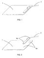
- FIGS 1 to 5 illustrate a first preferable embodiment of the kitchen utensil according to the invention, in which:
- Figure 1 shows a perspective view of this first embodiment, in which the cooking plate 1 is coupled to the handle 2.
- Figure 2 shows these two members decoupled from each other, in a position prior to their coupling: the magnets 4a of said handle 2 face the magnets 4b of said cooking plate.
- said magnets 4a, 4b are represented with a broken line, since they are hidden from the upper oblique viewpoint of the figure.
- the cooking plate 1 has a rectangular shape, with rounded edges, and a relatively slight thickness which, depending on the total dimensions of the plate, is however sufficient to ensure its mechanical strength when loaded and sustained by said handle.
- Its upper surface or cooking surface is totally flat.
- the two magnets 4b are housed through the lower surface of said cooking plate 1, and as such are not visible from said upper surface. With the aim of easing the positioning of said handle 2 with respect to said cooking plate 1 for its coupling, said upper surface can have some markings or drawings, not represented, which indicate the position of said magnets.
- Said magnets 4b which constitute the points at which said plate 1 is joined with said handle 2, are identical, have a cylindrical pill shape and are situated adjacent to one of the edges of said plate, parallel to said edge, near its corners.
- said magnets 4b are housed in cylindrical bores made in the lower surface of said cooking plate 1.
- the lower surface of said cooking plate 1 is totally flat, except as concerns the bores which house said magnets 4b, such that it is suitable for use on any support, and especially on electric or vitroceramic kitchen hotplates.
- the handle 2 comprises a bearing surface 3 joined to a haft 5 which has a joining end-member 8 of cone frustum shape, prolonged by an elbowed arm 7 which is hollow and has a circular section which in turn is prolonged at its end by a hand piece 6.
- said bearing surface 3 and the members of said haft are made of metallic material, and the hand piece of thermal isolating material, such as wood or Bakelite.
- the haft 5 is joined to the bearing surface 3 by any suitable means, e.g. by welding.
- the bearing surface is flat, with an elongated rectangular shape and rounded edges.
- said magnets 4a are identical, have a cylindrical pill shape and are housed in cylindrical bores made in the lower face of said bearing surface 3, such that the lower face of said magnets 4a is substantially in the same plane as the lower surface of said bearing surface 3, and the line which passes through said magnets 4a is substantially separated, horizontally, from the axis of the joining end-member 8 with said bearing surface 3.
- Said magnets 4a, 4b can be fixed to said cooking plate 1 or to said bearing surface 3 of said handle 2 by any suitable means, such as for example high temperature resistant gluing.
- any suitable means such as for example high temperature resistant gluing.
- gluing using for example an appropriate mastic, the problem of the thermo-mechanic stresses induced by differential expansion as concerns the magnets and the material which houses them can be solved.
- said magnets 4a, 4b are such that the force of magnetic attraction which they exercise between them, through the thickness of the cooking plate 1 which remains between the magnets 4b and the cooking surface, is sufficient to ensure the support of said plate 1 when it is loaded and is lifted by means of said handle 2.
- the manoeuvre for decoupling said handle 2 with respect to said plate 1 is performed with said plate 1 being in repose on a supporting surface, such as e.g. a grill, and by exerting through said hand piece 6 a lever force such that a moment is transmitted which rotates the bearing surface 3 on its longer side in proximity to the magnets 4a, decoupling them from the magnets 4b of said cooking plate 1.
- Said decoupling manoeuvre can only be performed with ease when said plate 1 is supported by a surface, as indicated. Consequently, when said plate 1 is lifted by means of said handle 2, it is solidly joined to the latter by the magnetic force of the magnets, and cannot be detached except by a very brusque accelerative movement which is normally not produced in conventional use of said kitchen utensil.
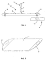
- FIG 6 shows a second embodiment similar to that of figures 1 to 5, but in which the removable fixation system by means of magnets has been replaced by a removable joining system by means of screws and screw nuts. Consequently, the bearing surface 3 has two through holes for two screws 9 and the cooking plate 1 has corresponding embedded screw nuts 10.
- FIG 7 shows a different embodiment of the invention.
- the cooking plate 1 has two handles 2 integrated which are made from the same material as the cooking plate 1 and the three members form a single physical member.
- This embodiment is particularly cheap to manufacture, and can be designed to be particularly easy to clean, i.e., without sharp angles nor inaccessible corners.
- a metallic material can be used.
- porous metallic materials such materials being for example sintered metals.
- the materials used are advantageously ceramic materials.
- a specific example of a suitable material is a powder which contains more than 95% in weight of silicocarbide, and the following grading:
- said plate 1 can have a plan which is rectangular, as in the embodiments illustrated, but could also be of oval or round shape or have any other shape in plan.
- said plate 1 can have drawings or peripheral slots in its cooking surface, for aesthetic reasons or for possible drainage of liquids.
- said plate 1 need not be homogenous; in particular, should the plate be ceramic, it could be reinforced interiorly with compound material to improve its thermo-mechanic properties.
- Magnets 4a and 4b can have other shapes than that of a cylindrical pill, and there may be more than two.
- said cooking plate 1 magnets 4b can be housed through the upper cooking surface instead of being housed through the lower surface as in the first embodiment represented.
- the bearing surface 3 can be arched, with flat bases to house the magnets or the screws, and the haft can be replaced by a different handle, such as for example a grip, as long as the ease and safety of the decoupling manoeuvre, such as described, is ensured should the removable join between said plate 1 and said handle 2 be by means of magnets.
- several handles 2 can be provided in one and the same cooking plate 1.
Landscapes
- Engineering & Computer Science (AREA)
- Food Science & Technology (AREA)
- Baking, Grill, Roasting (AREA)
- Cookers (AREA)
- Table Devices Or Equipment (AREA)
Applications Claiming Priority (2)
| Application Number | Priority Date | Filing Date | Title |
|---|---|---|---|
| ES200202518A ES2245533B1 (es) | 2002-11-04 | 2002-11-04 | Utensilio de cocina y utilizaciones correspondientes. |
| ES200202518 | 2002-11-04 |
Publications (2)
| Publication Number | Publication Date |
|---|---|
| EP1415581A2 true EP1415581A2 (de) | 2004-05-06 |
| EP1415581A3 EP1415581A3 (de) | 2006-08-09 |
Family
ID=32088167
Family Applications (1)
| Application Number | Title | Priority Date | Filing Date |
|---|---|---|---|
| EP03380255A Withdrawn EP1415581A3 (de) | 2002-11-04 | 2003-11-03 | Küchengerät und entsprechende Anwendung |
Country Status (2)
| Country | Link |
|---|---|
| EP (1) | EP1415581A3 (de) |
| ES (1) | ES2245533B1 (de) |
Cited By (2)
| Publication number | Priority date | Publication date | Assignee | Title |
|---|---|---|---|---|
| EP1892477A3 (de) * | 2006-08-23 | 2010-10-20 | Electrolux Home Products, Inc (a corporation of Delaware) | Backgestell mit Steinplatte |
| EP2601871A1 (de) | 2011-12-09 | 2013-06-12 | ARC International France | Abnehmbarer Griff und Kochutensil für einen solchen Griff |
Citations (1)
| Publication number | Priority date | Publication date | Assignee | Title |
|---|---|---|---|---|
| EP0623303A1 (de) | 1993-04-28 | 1994-11-09 | Moulinex S.A. | Elektrisches Kochgerät |
Family Cites Families (11)
| Publication number | Priority date | Publication date | Assignee | Title |
|---|---|---|---|---|
| ES130460Y (es) * | 1967-05-20 | 1968-09-01 | Mery, S. A. | Asador portatil para carnes y pescado. |
| CH525661A (de) * | 1970-01-26 | 1972-07-31 | Schwaderlapp Heinz | Zwieteiliger Topf zum fettfreien Braten |
| FR2207672B1 (de) * | 1972-11-24 | 1976-08-20 | Leroy Jean Georges | |
| US4681027A (en) * | 1978-04-24 | 1987-07-21 | Meamber Jon F | Rapid cooking apparatus for egg frying utensil |
| FR2641604B1 (fr) * | 1988-12-16 | 1991-03-01 | Lagrange Cie Ets | Appareil de cuisson comportant un bloc de chauffage en matiere minerale |
| FR2644561A1 (fr) * | 1989-03-17 | 1990-09-21 | Charpillon Agnes | Appareil de cuisson autonome d'aliments |
| ES2020143A6 (es) * | 1989-05-17 | 1991-07-16 | Didier Werke Ag | Placa de ceramica. |
| DE9106884U1 (de) * | 1991-06-05 | 1991-07-25 | ABC-Elektrogeräte Volz, GmbH & Co, 7312 Kirchheim | Steingrill |
| JPH08187185A (ja) * | 1995-01-11 | 1996-07-23 | Satoru Yoshinaka | セラミックグリル器 |
| FR2747904B1 (fr) * | 1996-04-30 | 1998-07-17 | Cheminees Seguin Duteriez Sa | Barbecue a foyer ventile |
| FR2783664B1 (fr) * | 1998-09-18 | 2002-01-18 | Frederique Lego | Dispositif pour chauffer et maintenir en temperature une plaque independante en pierre de lave ou autre pierre naturelle dont la surface peut etre traitee ou non |
-
2002
- 2002-11-04 ES ES200202518A patent/ES2245533B1/es not_active Expired - Fee Related
-
2003
- 2003-11-03 EP EP03380255A patent/EP1415581A3/de not_active Withdrawn
Patent Citations (1)
| Publication number | Priority date | Publication date | Assignee | Title |
|---|---|---|---|---|
| EP0623303A1 (de) | 1993-04-28 | 1994-11-09 | Moulinex S.A. | Elektrisches Kochgerät |
Cited By (3)
| Publication number | Priority date | Publication date | Assignee | Title |
|---|---|---|---|---|
| EP1892477A3 (de) * | 2006-08-23 | 2010-10-20 | Electrolux Home Products, Inc (a corporation of Delaware) | Backgestell mit Steinplatte |
| US8499944B2 (en) | 2006-08-23 | 2013-08-06 | Electrolux Home Products, Inc. | Baking stone rack |
| EP2601871A1 (de) | 2011-12-09 | 2013-06-12 | ARC International France | Abnehmbarer Griff und Kochutensil für einen solchen Griff |
Also Published As
| Publication number | Publication date |
|---|---|
| EP1415581A3 (de) | 2006-08-09 |
| ES2245533B1 (es) | 2007-05-01 |
| ES2245533A1 (es) | 2006-01-01 |
Similar Documents
| Publication | Publication Date | Title |
|---|---|---|
| US10058210B2 (en) | Versatile cooker | |
| US20130312732A1 (en) | Gas and ceramic grill combination | |
| US7703387B2 (en) | Steak weight | |
| US11690483B2 (en) | Cookware system with removable handles | |
| KR101167657B1 (ko) | 회전형 구이용 그릴 | |
| TWM438884U (en) | Electromagnetic frying and grilling device | |
| KR101490601B1 (ko) | 구이용 보조불판 및 이를 이용한 2단 불판유닛 | |
| KR100909072B1 (ko) | 식탁용 조리기 | |
| KR20120121497A (ko) | 찜 구이용 조리기 | |
| EP1415581A2 (de) | Küchengerät und entsprechende Anwendung | |
| KR101428558B1 (ko) | 다용도 및 다기능 불판 | |
| US8137723B1 (en) | Healthy cookware | |
| KR20040099212A (ko) | 구이판을 포함하는 조리테이블 | |
| US20060090743A1 (en) | Combined griddle, wok and grill cookware | |
| CN205493603U (zh) | 一种多功能煎烤盘 | |
| KR20040091905A (ko) | 고기구이기 | |
| KR200249198Y1 (ko) | 석쇠판 및 고기구이판 겸용 고기구이기 | |
| CN107319908B (zh) | 一种多功能炊具 | |
| KR20170027039A (ko) | 다기능 불판 | |
| KR200266752Y1 (ko) | 뚜껑이 분리되는 솥뚜껑형 구이판 | |
| US20050205078A1 (en) | Bench top grill assembly | |
| KR102317772B1 (ko) | 간접 가열식 일인용 구이기 | |
| JP3126629U (ja) | 炭素成型体が装着されたセラミック調理器具 | |
| KR200408124Y1 (ko) | 다목적 구이기 | |
| KR20120041387A (ko) | 고기구이판 |
Legal Events
| Date | Code | Title | Description |
|---|---|---|---|
| PUAI | Public reference made under article 153(3) epc to a published international application that has entered the european phase |
Free format text: ORIGINAL CODE: 0009012 |
|
| AK | Designated contracting states |
Kind code of ref document: A2 Designated state(s): AT BE BG CH CY CZ DE DK EE ES FI FR GB GR HU IE IT LI LU MC NL PT RO SE SI SK TR |
|
| AX | Request for extension of the european patent |
Extension state: AL LT LV MK |
|
| PUAL | Search report despatched |
Free format text: ORIGINAL CODE: 0009013 |
|
| AK | Designated contracting states |
Kind code of ref document: A3 Designated state(s): AT BE BG CH CY CZ DE DK EE ES FI FR GB GR HU IE IT LI LU MC NL PT RO SE SI SK TR |
|
| AX | Request for extension of the european patent |
Extension state: AL LT LV MK |
|
| RIC1 | Information provided on ipc code assigned before grant |
Ipc: A47J 36/04 20060101ALI20060706BHEP Ipc: A47J 37/06 20060101AFI20060706BHEP |
|
| 17P | Request for examination filed |
Effective date: 20061118 |
|
| AKX | Designation fees paid |
Designated state(s): AT BE BG CH CY CZ DE DK EE ES FI FR GB GR HU IE IT LI LU MC NL PT RO SE SI SK TR |
|
| 17Q | First examination report despatched |
Effective date: 20070705 |
|
| STAA | Information on the status of an ep patent application or granted ep patent |
Free format text: STATUS: THE APPLICATION IS DEEMED TO BE WITHDRAWN |
|
| 18D | Application deemed to be withdrawn |
Effective date: 20100601 |