EP1414094A2 - Structure de pile à combustible - Google Patents
Structure de pile à combustible Download PDFInfo
- Publication number
- EP1414094A2 EP1414094A2 EP20030256549 EP03256549A EP1414094A2 EP 1414094 A2 EP1414094 A2 EP 1414094A2 EP 20030256549 EP20030256549 EP 20030256549 EP 03256549 A EP03256549 A EP 03256549A EP 1414094 A2 EP1414094 A2 EP 1414094A2
- Authority
- EP
- European Patent Office
- Prior art keywords
- fuel cell
- flame
- oxide type
- solid oxide
- type fuel
- Prior art date
- Legal status (The legal status is an assumption and is not a legal conclusion. Google has not performed a legal analysis and makes no representation as to the accuracy of the status listed.)
- Granted
Links
Images


Classifications
-
- H—ELECTRICITY
- H01—ELECTRIC ELEMENTS
- H01M—PROCESSES OR MEANS, e.g. BATTERIES, FOR THE DIRECT CONVERSION OF CHEMICAL ENERGY INTO ELECTRICAL ENERGY
- H01M8/00—Fuel cells; Manufacture thereof
- H01M8/10—Fuel cells with solid electrolytes
- H01M8/12—Fuel cells with solid electrolytes operating at high temperature, e.g. with stabilised ZrO2 electrolyte
- H01M8/1213—Fuel cells with solid electrolytes operating at high temperature, e.g. with stabilised ZrO2 electrolyte characterised by the electrode/electrolyte combination or the supporting material
-
- H—ELECTRICITY
- H01—ELECTRIC ELEMENTS
- H01M—PROCESSES OR MEANS, e.g. BATTERIES, FOR THE DIRECT CONVERSION OF CHEMICAL ENERGY INTO ELECTRICAL ENERGY
- H01M8/00—Fuel cells; Manufacture thereof
- H01M8/24—Grouping of fuel cells, e.g. stacking of fuel cells
- H01M8/241—Grouping of fuel cells, e.g. stacking of fuel cells with solid or matrix-supported electrolytes
- H01M8/2425—High-temperature cells with solid electrolytes
- H01M8/2432—Grouping of unit cells of planar configuration
-
- H—ELECTRICITY
- H01—ELECTRIC ELEMENTS
- H01M—PROCESSES OR MEANS, e.g. BATTERIES, FOR THE DIRECT CONVERSION OF CHEMICAL ENERGY INTO ELECTRICAL ENERGY
- H01M8/00—Fuel cells; Manufacture thereof
- H01M8/10—Fuel cells with solid electrolytes
- H01M8/12—Fuel cells with solid electrolytes operating at high temperature, e.g. with stabilised ZrO2 electrolyte
- H01M8/124—Fuel cells with solid electrolytes operating at high temperature, e.g. with stabilised ZrO2 electrolyte characterised by the process of manufacturing or by the material of the electrolyte
-
- Y—GENERAL TAGGING OF NEW TECHNOLOGICAL DEVELOPMENTS; GENERAL TAGGING OF CROSS-SECTIONAL TECHNOLOGIES SPANNING OVER SEVERAL SECTIONS OF THE IPC; TECHNICAL SUBJECTS COVERED BY FORMER USPC CROSS-REFERENCE ART COLLECTIONS [XRACs] AND DIGESTS
- Y02—TECHNOLOGIES OR APPLICATIONS FOR MITIGATION OR ADAPTATION AGAINST CLIMATE CHANGE
- Y02E—REDUCTION OF GREENHOUSE GAS [GHG] EMISSIONS, RELATED TO ENERGY GENERATION, TRANSMISSION OR DISTRIBUTION
- Y02E60/00—Enabling technologies; Technologies with a potential or indirect contribution to GHG emissions mitigation
- Y02E60/30—Hydrogen technology
- Y02E60/50—Fuel cells
-
- Y—GENERAL TAGGING OF NEW TECHNOLOGICAL DEVELOPMENTS; GENERAL TAGGING OF CROSS-SECTIONAL TECHNOLOGIES SPANNING OVER SEVERAL SECTIONS OF THE IPC; TECHNICAL SUBJECTS COVERED BY FORMER USPC CROSS-REFERENCE ART COLLECTIONS [XRACs] AND DIGESTS
- Y02—TECHNOLOGIES OR APPLICATIONS FOR MITIGATION OR ADAPTATION AGAINST CLIMATE CHANGE
- Y02P—CLIMATE CHANGE MITIGATION TECHNOLOGIES IN THE PRODUCTION OR PROCESSING OF GOODS
- Y02P70/00—Climate change mitigation technologies in the production process for final industrial or consumer products
- Y02P70/50—Manufacturing or production processes characterised by the final manufactured product
Definitions
- the present invention relates to a fuel cell. More particularly, the present invention relates to a fuel cell structure used when a solid oxide type fuel cell element is arranged in a flame or in a portion close to the flame.
- JP-A-6-196176 discloses a solid oxide type fuel cell including: a tube body made of zirconia solid electrolyte; a fuel electrode arranged outside the tube body; and an air electrode arranged inside the tube body, wherein the solid oxide type fuel cell is arranged so that the fuel electrode is exposed to a reducing flame portion of the flame.
- This fuel cell generates electricity in such a manner that radicals and others existing in the reducing flame are utilized as fuel and air is supplied into the tube by means of convection or diffusion.
- the flame is directly used. Therefore, the electro-motive time can be reduced. Further, the structure of the fuel cell is so simple that the size and weight can be reduced, by which the manufacturing cost can be advantageously lowered. Furthermore, it is possible to utilize a combustion device, an incinerator and the like as an electric power supply device. Therefore, the utility value of this type fuel cell is high.
- the present invention has been accomplished to solve the above mentioned-problems of the related art.
- a cathode layer and an anode layer are made of porous material so that gas can smoothly pass through the cathode layer and the anode layer.
- a solid electrolyte layer is so densely formed that the thermal shock resistance is low. Therefore, cracks caused by a sudden temperature change on the solid electrolyte layer becomes a trigger, and the entire solid oxide type fuel cell cracks and breaks up. Accordingly, the inventors of the present application thought that the thermal shock resistance of the solid oxide type fuel cell element can be enhanced when the solid electrolyte player is made of porous material. In this way, the present invention has been accomplished.
- a fuel cell comprising a solid oxide type fuel cell element comprising a solid electrolyte layer having respective faces, a cathode layer formed on one of faces of the solid electrolyte layer and an anode layer formed on the other face of the solid electrolyte layer, wherein said element generates electricity when said solid oxide type fuel cell element is arranged in a flame or in a portion close to the flame; the solid electrolyte layer being made of porous material, the porosity of which is not less than 10%, so that cracks can not be caused on the solid electrolyte layer by a sudden temperature change in the solid oxide type fuel cell when the solid oxide type fuel cell is arranged in the flame or in the portion close to the flame or when the solid oxide type fuel cell is separated from the flame or the portion close to the flame.
- the thermal shock resistance can be enhanced.
- the present invention provides a fuel cell, wherein a mesh-shaped metal or a wire-shaped metal is embedded in or fixed to at least one of the anode layer and the cathode layer so as to reinforce the anode layer or the cathode layer.
- the solid oxide type fuel cell does not break up, and further an electrical connection can be accomplished by the mesh-shaped metal or wire-shaped metal. Accordingly, the electricity generating capacity as a fuel cell can be maintained.
- the anode layer When the anode layer is arranged on the flame side, it becomes easy for radicals existing in the flame to be used as fuel for generating electricity according to the oxidizing and reducing reaction.
- the cathode layer When the cathode layer is arranged so that it can be exposed to gas containing oxygen, oxygen can be easily utilized from the cathode layer. Further, when gas containing oxygen is blown to the cathode layer, oxygen can be more effectively utilized from the cathode layer.
- the anode layer is composed of a sintered body, the primary component of which is conductive oxide. Due to the foregoing, deterioration of the efficiency of generating electricity and incompetence of generating electricity, which are caused by oxidation of the anode layer, can be prevented. Further, it is possible to prevent the anode layer from peeling off from the solid electrolyte layer. It is preferable that the conductive oxide is nickel oxide in which lithium is solidly dissolved.
- Fig. 1 is a sectional view for explaining a structure of a fuel cell of the present invention.
- Fig. 2 is a sectional view showing an example of a solid oxide type fuel cell element used for a fuel cell of the present invention.
- the solid oxide type fuel cell element 15 used for the fuel cell of the present invention is composed in such a manner that the cathode layer 11 is provided on one face of the solid electrolyte layer 13 and the anode layer 12 is provided on the other face and the entire solid oxide type fuel cell element 15 is formed flat.
- the solid oxide type fuel cell element 15 is arranged in the flame 20 or in a portion close the flame 20 while the anode layer 12 is being directed to the flame 20 side, electricity is generated.
- Electric power generated by the solid oxide type fuel cell element 15 is taken out by the leads 16, 16 which are respectively drawn out from anode layer 12 and the cathode layer 11.
- the leads 16, 16 are made of platinum or platinum alloy, the heat resistance property of which is high.
- the solid oxide type fuel cell 15 is formed flat, it is possible to blow a flame to the solid oxide type fuel cell element 15 more uniformly than a fuel cell element formed into a tube-shape. Further, it is advantageous that the anode layer 12 is arranged being directed toward the flame side, because hydrocarbon, hydrogen, radicals (OH, CH, C 2 , O 2 H and CH 3 ) existing in the flame can be more easily utilized as fuel.
- the cathode layer 11 can be more effectively exposed to the atmospheric air. Due to the foregoing, it is possible for the cathode layer 11 to utilize oxygen contained in the atmospheric air more easily. Further, as shown by the arrow in Fig. 1, gas such as air or oxygen-rich gas may be blown to the cathode layer 11 so that the cathode layer 11 can be more effectively utilize oxygen.
- the solid oxide type fuel cell element 15 is arranged in the flame or in a portion close to the flame. Therefore, hydrocarbon, hydrogen, radicals existing in the flame can be effectively utilized as fuel. Even the anode layer, which tends to be deteriorated by oxidation, can be steadily used and the durability can be maintained over a long period of time.
- any fuel can be used. Accordingly, phosphorus, sulfur, fluorine, chlorine and chemical compounds of them may be used as the fuel.
- organic substance fuel are: gas such as methane, ethane, propane and butane; liquid fuel of gasoline such as hexane, heptane and octane; alcohol such as methanol, ethanol and propanol; ketone such as acetone; various organic solvents; edible oil; kerosene; paper; and wood.
- gas fuel is preferably used.
- the flame may be a diffusion flame or a premixed flame.
- the diffusion flame is not stable and generates so much soot that the function of the anode layer tends to be deteriorated by the soot. Therefore, it is preferable to use the premixed flame. It is advantageous to use the premixed flame, because the premixed flame is stable and further the flame size of the premixed flame can be easily adjusted and further it is possible to prevent the generation of soot by adjusting the fuel concentration.
- solid electrolyte layer 13 Concerning the solid electrolyte layer 13, for example, it is possible to use a well known solid electrolyte layer. However, the following solid electrolyte layers may be preferably used.
- anode layer 12 Concerning the anode layer 12, it is possible to adopt a well known anode layer.
- Preferable examples of the anode layer are as follows.
- item (2) or (3) is more preferable.
- the primary component of which is the conductive oxide described in item (2) is high. Therefore, it is possible to prevent the deterioration of the electric power generation efficiency, the incompetence of electric power generation and the separation of the anode layer from the solid electrolyte layer which are caused by an increase in the electrode resistance of the anode layer caused by the oxidation of the anode layer.
- Concerning the conductive oxide nickel oxide into which lithium is solidly dissolved can be preferably used.
- cathode layer 11 it is possible to use a well known cathode layer.
- the cathode layer are: manganese of lanthanum (for example, lanthanum strontium manganite) to which the third group element of the periodic table such as strontium (Sr) is added; and gallium oxide compound or cobalt oxide compound (for example, lanthanum strontium cobaltite).
- Both the anode layer and the cathode layer are composed of a porous body. Further, in the present invention, the solid electrolyte layer is also composed of a porous body.
- a solid electrolyte layer is so densely formed that the thermal shock resistance is low. Therefore, cracks tend to be caused by a sudden temperature change on the solid electrolyte layer.
- the thickness of the solid electrolyte layer is larger than the thickness of the anode layer and cathode layer. Therefore, cracks caused by a sudden temperature change on the solid electrolyte layer becomes a trigger of cracks, and the entire solid oxide type fuel cell element cracks and breaks up.
- the solid electrolyte layer is composed of a porous body, even when the solid electrolyte layer is arranged in a flame or in a portion close to the flame and given a sudden thermal change, and even when the solid electrolyte layer is subjected to a heat cycle, the temperature difference of which is large, no cracks are caused and the thermal shock resistance is enhanced. Even if the solid electrolyte layer was made of a porous body, when the porosity was lower than 10%, the thermal shock resistance could not be remarkably enhanced, however, when the porosity was not less than 10%, the thermal shock resistance could be enhanced. Further, when the porosity was not less than 20%, the thermal shock resistance could be more preferably enhanced.
- the reason why the thermal shock resistance can be enhanced is estimated as follows. Since the solid electrolyte layer is porous, the thermal expansion caused by heating is relieved by gap portions formed in the porous body. Therefore, it is desirable to design in such a manner that the porosity is determined while giving consideration to the field of utilization of the fuel cell.
- the solid oxide type fuel cell element is manufactured, for example, by the following manufacturing method.
- material power of the solid electrolyte layer is blended by a predetermined ratio and formed into a flat-plate-shape. After that, the thus formed flat-plate-shaped body is burned and sintered so that a base board of the solid electrolyte layer is made.
- the type of material powder such as a blow hole forming agent and the blending ratio are adjusted and when the burning conditions such as a burning temperature, burning time and preburning are adjusted, it is possible to make solid electrolyte layers of various porosity.
- One face of the base board of the thus obtained solid electrolyte layer is coated with paste which becomes a cathode layer, and the other face is coated with paste which becomes an anode layer. Then, the base board of the thus obtained solid electrolyte layer is burned. In this way, the solid oxide type fuel cell element can be manufactured.
- the durability can be more enhanced.
- the mesh-shaped metal 17 is embedded in or fixed to the anode layer 12 and the cathode layer 11 of the flat-plate-shaped solid oxide type fuel cell element 15 shown in Fig. 1.
- the solid electrolyte layer is coated with material (paste) of each layer and the mesh-shaped metal is embedded in the coated material and then burned.
- the mesh-shaped metal may be bonded and sintered without completely embedding the mesh-shaped material in each layer.
- the mesh-shaped metal 17 it is preferable to use metal, the coefficient of thermal expansion of which agrees with that of the anode layer and the cathode layer, and further the heat resistance property of which is high.
- a specific example of the mesh-shaped metal 17 is a mesh-shaped metal containing platinum or platinum alloy.
- a specific example of the mesh-shaped metal 17 is stainless steel (SUS 304, 316 and 430). When stainless steel is used for the mesh-shaped metal 17, the manufacturing cost can be advantageously decreased.
- the wire-shaped metal may be embedded in or fixed to the anode layer and the cathode layer.
- the wire-shaped metal is made of the same metal as that of the mesh-shaped metal, and the number and the arranging profile of the wire-shaped metal are not particularly limited.
- the solid oxide type fuel cell element which has been cracked due to the thermal hysteresis, can be reinforced so that it can not break up. Further, the cracked portions of the mesh-shaped metal and the wire-shaped metal can be electrically connected.
- the mesh-shaped metal or the wire-shaped metal may be arranged on both the anode layer and the cathode layer. Alternatively, the mesh-shaped metal or the wire-shaped metal may be arranged on one of the anode layer and the cathode layer. Alternatively, the mesh-shaped metal and the wire-shaped metal may be arranged being combined with each other.
- the mesh-shaped or the wire-shaped metal is embedded at least in the anode layer, the generation of electric power can be continued without deteriorating the electric power generating capacity.
- the electric power generating capacity of the solid oxide type fuel cell greatly owes the effective area of the anode layer which functions as an electrode. Therefore, it is preferable that the mesh-shaped metal or the wire-shaped metal is arranged at least on the anode layer.
- a range on each of the anode layer and the cathode layer in which the mesh-shaped metal or the wire-shaped metal is arranged is preferably a range, the area of which is not less than 50% and not more than 100% of the boundary area of the solid electrolyte layer and each layer.
- the anode layer or the cathode layer may be partially arranged in a portion where cracks tend to be caused.
- the mesh-shaped metal or the wire-shaped metal positively reinforces the solid oxide type fuel cell element and the electrical connection of the fuel cell element can be maintained.
- a ceramic base board of Sm 0.2 Ce 0.8 O 1.9 (samarium doped ceria: SDC), the porosity of which is approximately 20%, is used as the solid electrolyte layer.
- the platinum mesh which is a mesh-shaped metal formed by welding a platinum wire, was embedded in each printed face and burned for one hour at 1200°C in the atmospheric air. In this way, the solid oxide type fuel cell element was made.
- the size of the premixed flame was sufficiently large so that it came to the cathode layer side.
- the solid oxide type fuel cell element was able to generate electric power without being cracked.
- the maximum electric current was 88 mA and the maximum open circuit voltage was 0.47 V.
- the solid oxide type fuel cell element was subjected to a heat cycle test in which the premixed flame, which was blown to the anode layer, was repeatedly turned on and off. As a result of the heat cycle test, even if the premixed flame was turned on and off by 20 times, no cracks were caused.
- a premixed flame of a gas lighter was blown to the anode layer of the solid oxide type fuel cell element obtained in the same manner as that of Embodiment 1. At this time, the size of the flame was not so large that it did not come to the cathode layer side. In this case, the solid oxide type fuel cell element was able to generate electric power without causing any cracks, and the maximum electric current was 81 mA and the maximum open circuit voltage was 0.82 V.
- the solid oxide type fuel cell element was able to generate electric power without causing any cracks, and the maximum electric current was 74 mA and the maximum open circuit voltage was 0.80 V.
- a diffusion flame of a candle was blown to the anode layer of the solid oxide type fuel cell element obtained in the same manner as that of Embodiment 1.
- the solid oxide type fuel cell was able to generate electric power without causing any cracks, and the electric current fluctuated in the range from 2 to 30 mA, and the open circuit voltage fluctuates in the range from 0.01 to 0.5 V.
- a platinum wire connected to one of the anode layers of the two solid oxide type fuel cell elements obtained in the same manner as that of Embodiment 1 and a platinum wire connected to the other cathode layer were welded to each other, and a platinum wire connected to the remaining cathode layer and a platinum wire connected to the anode layer were connected to a multiple-meter.
- a diffusion flame of an alcohol lamp, the fuel of which was ethanol was blown to the respective anode layers.
- the solid oxide type fuel cell element was able to generate electric power without causing any cracks, and the maximum electric current was 46 mA and the maximum open circuit voltage was 1.64 V.
- a diffusion flame of burning kitchen paper was blown to the anode layer of the solid oxide type fuel cell obtained in the same manner as that of Embodiment 1.
- the solid oxide type fuel cell element was capable of generating electric power without causing any cracks.
- the electric current fluctuated in the range from 0.1 to 2 mA, and the maximum open circuit voltage was 0.80 V.
- a ceramic base board of Sm 0.2 Ce 0.8 O 1.9 (samarium doped ceria: SDC), the porosity of which was approximately 20%, was used as the solid electrolyte layer.
- the platinum mesh which is a mesh-shaped metal formed by welding a platinum wire, was embedded in each printed face and burned for one hour at 1100°C in the atmospheric air. In this way, the solid oxide type fuel cell element was made.
- the maximum electric current was 148 mA and the maximum open circuit voltage was 0.89 V.
- a platinum wire connected to one of the anode layers of the two solid oxide type fuel cell elements obtained in the same manner as that of Embodiment 7 and a platinum wire connected to the other cathode layer were welded to each other, and a platinum wire connected to the remaining cathode layer and a platinum wire connected to the anode layer were connected to a multiple-meter.
- a diffusion flame of an alcohol lamp, the fuel of which was ethanol was blown to the respective anode layers.
- the solid oxide type fuel cell element was able to generate electric power without causing any cracks, and the maximum electric current was 120 mA and the maximum open circuit voltage was 2.24 V.
- the solid oxide type fuel cell element was made in Embodiment 9 in the same manner as that of Embodiment 1 except for one point in which SDC ceramic base board, the porosity of which was approximately 10%, was used instead of SDC ceramic base board, the porosity of which was approximately 20%.
- Embodiment 9 was substantially the same as that of Embodiment 1.
- the solid oxide type fuel cell element was subjected to a heat cycle test in which a premixed flame, which was blown to the anode layer, was repeatedly turned on and off.
- a premixed flame which was blown to the anode layer
- cracks were caused on the entire solid oxide type fuel cell element.
- the solid oxide type fuel cell element did not break up, and it was confirmed that the electric power generating capacity was substantially the same as that of Embodiment 1.
- the solid oxide type fuel cell element was made in Comparative Example 1 in the same manner as that of Embodiment 1 except for two points that a dense SDC ceramic base board, the porosity of which was not more than 5%, was used instead of SDC ceramic base board, the porosity of which was approximately 20% and that the platinum mesh was not embedded in the printed face.
- SDC ceramic base board was cracked and the solid oxide type fuel cell element broke up into pieces.
- Embodiment 1 and Comparative Example 1 are compared with each other, it can be understood that the thermal shock resistance is enhanced when the porous solid electrolyte layer is used. Further, when Embodiment 1 and Embodiment 9 are compared with each other, it can be understood that an increase in the porosity is effective for improving the thermal shock resistance and the platinum mesh is effective for reinforcing the solid oxide type fuel cell element.
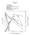
- the cell performance is also shown in Fig. 4 for the solid fuels; candle (paraffin wax) and wood pieces. While a natural flame of the candle gave output cell voltage (OCV) of 0.84 V, its output was up to 12 mW/cm 2 . By a supply of slight air to the wick, the power density improved up to 62 mW/cm 2 , here also, greater than that of ethanol. Although OCV reached around 0.8 V, the control of the flame was most difficult for the wood pieces, accordingly the lowest power density, 5 mW/cm 2 was obtained. These results strongly suggest that the flaming condition has a significant role for the output, and any fuel is able to liberate a higher power proper for the molecule, when an appropriate amount of air is given. Wood must become higher energy provider if it is flamed optimally.
- a flame may be mainly used for holding the operation temperature of the solid oxide type fuel cell element and fuel may be supplied by a fuel supplying device.
- a size of the fuel cell of the present invention can be easily decreased. Therefore, the fuel cell of the present invention can be used as a simple electric power supplying unit to operate an illuminating device, for example, to operate an illuminating device with a bonfire.
Landscapes
- Life Sciences & Earth Sciences (AREA)
- Engineering & Computer Science (AREA)
- Manufacturing & Machinery (AREA)
- Sustainable Development (AREA)
- Sustainable Energy (AREA)
- Chemical & Material Sciences (AREA)
- Chemical Kinetics & Catalysis (AREA)
- Electrochemistry (AREA)
- General Chemical & Material Sciences (AREA)
- Fuel Cell (AREA)
- Inert Electrodes (AREA)
- Compositions Of Oxide Ceramics (AREA)
Applications Claiming Priority (2)
| Application Number | Priority Date | Filing Date | Title |
|---|---|---|---|
| JP2002305769 | 2002-10-21 | ||
| JP2002305769A JP4104418B2 (ja) | 2002-10-21 | 2002-10-21 | 燃料電池 |
Publications (3)
| Publication Number | Publication Date |
|---|---|
| EP1414094A2 true EP1414094A2 (fr) | 2004-04-28 |
| EP1414094A3 EP1414094A3 (fr) | 2005-04-13 |
| EP1414094B1 EP1414094B1 (fr) | 2008-12-03 |
Family
ID=32064280
Family Applications (1)
| Application Number | Title | Priority Date | Filing Date |
|---|---|---|---|
| EP03256549A Expired - Lifetime EP1414094B1 (fr) | 2002-10-21 | 2003-10-17 | Structure de pile à combustible |
Country Status (5)
| Country | Link |
|---|---|
| US (1) | US7244525B2 (fr) |
| EP (1) | EP1414094B1 (fr) |
| JP (1) | JP4104418B2 (fr) |
| CA (1) | CA2445735C (fr) |
| DE (1) | DE60325003D1 (fr) |
Cited By (7)
| Publication number | Priority date | Publication date | Assignee | Title |
|---|---|---|---|---|
| EP1507305A2 (fr) * | 2003-08-11 | 2005-02-16 | Shinko Electric Industries Co., Ltd. | Dispositif de pile à combustible à électrolyte solide |
| EP1657773A1 (fr) * | 2003-08-21 | 2006-05-17 | Shinko Electric Industries Co., Ltd. | Generateur a pile a combustible a electrolyte solide |
| EP1675202A1 (fr) * | 2004-12-21 | 2006-06-28 | Shinko Electric Industries Co., Ltd. | Pile à combustible à oxyde solide avec chambre de combustion interne |
| EP1679759A3 (fr) * | 2005-01-07 | 2007-04-04 | Shinko Electric Industries Co., Ltd. | Cellule à combustible |
| EP1675204A3 (fr) * | 2004-12-22 | 2007-05-09 | Shinko Electric Industries Co., Ltd. | Pile à combustible |
| EP1936728A1 (fr) * | 2006-12-14 | 2008-06-25 | Shinko Electric Industries Co., Ltd. | Structure de pile à combustible à flamme directe |
| EP1939965A1 (fr) * | 2006-12-26 | 2008-07-02 | Shinko Electric Industries Co., Ltd. | Générateur de puissance à pile à combustible à oxyde solide |
Families Citing this family (16)
| Publication number | Priority date | Publication date | Assignee | Title |
|---|---|---|---|---|
| JP4859375B2 (ja) * | 2005-03-04 | 2012-01-25 | 新光電気工業株式会社 | 燃料電池発電システム |
| JP2006253016A (ja) * | 2005-03-11 | 2006-09-21 | Shinko Electric Ind Co Ltd | 固体酸化物燃料電池装置 |
| JP2006324190A (ja) | 2005-05-20 | 2006-11-30 | Shinko Electric Ind Co Ltd | 固体酸化物型燃料電池およびその製造方法 |
| JP5153062B2 (ja) | 2005-07-13 | 2013-02-27 | 新光電気工業株式会社 | 固体酸化物型燃料電池 |
| JP4953596B2 (ja) * | 2005-07-19 | 2012-06-13 | 新光電気工業株式会社 | 固体酸化物型燃料電池発電装置 |
| JP2007026942A (ja) * | 2005-07-19 | 2007-02-01 | Shinko Electric Ind Co Ltd | 固体酸化物型燃料電池利用の発電装置 |
| JP2007042354A (ja) * | 2005-08-02 | 2007-02-15 | Paloma Ind Ltd | 燃料電池の発電方法及びそれに用いるガスバーナ並びにそのガスバーナを備えたガス器具 |
| JP2007066578A (ja) * | 2005-08-29 | 2007-03-15 | Shinko Electric Ind Co Ltd | 直接火炎型燃料電池利用の発電装置 |
| US20070154759A1 (en) * | 2005-11-30 | 2007-07-05 | Shinko Electric Industries Co., Ltd. | Solid oxide fuel cell electric power generation apparatus |
| JP2007157336A (ja) * | 2005-11-30 | 2007-06-21 | Shinko Electric Ind Co Ltd | 固体酸化物型燃料電池利用の発電装置 |
| WO2007088925A1 (fr) * | 2006-02-02 | 2007-08-09 | Ritsumeikan Trust | Element de pile a combustible, module a pile a combustible, systeme cogenerateur de chaleur/energie et vehicule equipe de ce systeme, et procede de fonctionnement de pile a combustible |
| JP4861735B2 (ja) * | 2006-03-30 | 2012-01-25 | 新光電気工業株式会社 | 固体電解質燃料電池及びその製造方法 |
| JP2008140549A (ja) | 2006-11-29 | 2008-06-19 | Shinko Electric Ind Co Ltd | 燃料電池セルスタック用集電体及びそれを用いた直接火炎型燃料電池モジュール |
| JP4999436B2 (ja) * | 2006-12-01 | 2012-08-15 | 新光電気工業株式会社 | 直接火炎型燃料電池 |
| JP5361143B2 (ja) * | 2007-05-29 | 2013-12-04 | 新光電気工業株式会社 | 固体酸化物型燃料電池およびその製造方法 |
| JP2011210566A (ja) * | 2010-03-30 | 2011-10-20 | Mitsubishi Materials Corp | 固体酸化物形燃料電池の発電セルとその製造方法 |
Citations (2)
| Publication number | Priority date | Publication date | Assignee | Title |
|---|---|---|---|---|
| EP1261060A2 (fr) * | 2001-05-25 | 2002-11-27 | Shinko Electric Industries Co. Ltd. | Pile à combustible et empilement de plusieurs éléments pour celle-ci |
| EP1294036A2 (fr) * | 2001-09-17 | 2003-03-19 | Shinko Electric Industries Co. Ltd. | Pile à combustible |
Family Cites Families (3)
| Publication number | Priority date | Publication date | Assignee | Title |
|---|---|---|---|---|
| JPH0636782A (ja) * | 1992-07-15 | 1994-02-10 | Mitsubishi Heavy Ind Ltd | 固体電解質電解セル |
| JPH06196176A (ja) * | 1992-12-22 | 1994-07-15 | Matsushita Electric Ind Co Ltd | 燃焼装置 |
| US6004688A (en) * | 1997-07-16 | 1999-12-21 | The Board Of Regents Of The University Of Texas System | Solid oxide fuel cell and doped perovskite lanthanum gallate electrolyte therefor |
-
2002
- 2002-10-21 JP JP2002305769A patent/JP4104418B2/ja not_active Expired - Lifetime
-
2003
- 2003-10-17 EP EP03256549A patent/EP1414094B1/fr not_active Expired - Lifetime
- 2003-10-17 DE DE60325003T patent/DE60325003D1/de not_active Expired - Lifetime
- 2003-10-20 US US10/687,599 patent/US7244525B2/en active Active
- 2003-10-21 CA CA2445735A patent/CA2445735C/fr not_active Expired - Fee Related
Patent Citations (2)
| Publication number | Priority date | Publication date | Assignee | Title |
|---|---|---|---|---|
| EP1261060A2 (fr) * | 2001-05-25 | 2002-11-27 | Shinko Electric Industries Co. Ltd. | Pile à combustible et empilement de plusieurs éléments pour celle-ci |
| EP1294036A2 (fr) * | 2001-09-17 | 2003-03-19 | Shinko Electric Industries Co. Ltd. | Pile à combustible |
Non-Patent Citations (2)
| Title |
|---|
| PATENT ABSTRACTS OF JAPAN vol. 018, no. 252 (E-1547), 13 May 1994 (1994-05-13) & JP 06 036782 A (MITSUBISHI HEAVY IND LTD), 10 February 1994 (1994-02-10) * |
| PATENT ABSTRACTS OF JAPAN vol. 018, no. 540 (E-1616), 14 October 1994 (1994-10-14) & JP 06 196176 A (MATSUSHITA ELECTRIC IND CO LTD), 15 July 1994 (1994-07-15) * |
Cited By (11)
| Publication number | Priority date | Publication date | Assignee | Title |
|---|---|---|---|---|
| EP1507305A2 (fr) * | 2003-08-11 | 2005-02-16 | Shinko Electric Industries Co., Ltd. | Dispositif de pile à combustible à électrolyte solide |
| EP1507305A3 (fr) * | 2003-08-11 | 2006-01-04 | Shinko Electric Industries Co., Ltd. | Dispositif de pile à combustible à électrolyte solide |
| US7470480B2 (en) | 2003-08-11 | 2008-12-30 | Shinko Electric Industries Co., Ltd. | Solid electrolyte fuel-cell device |
| EP1657773A1 (fr) * | 2003-08-21 | 2006-05-17 | Shinko Electric Industries Co., Ltd. | Generateur a pile a combustible a electrolyte solide |
| EP1657773A4 (fr) * | 2003-08-21 | 2008-08-13 | Shinko Electric Ind Co | Generateur a pile a combustible a electrolyte solide |
| EP1675202A1 (fr) * | 2004-12-21 | 2006-06-28 | Shinko Electric Industries Co., Ltd. | Pile à combustible à oxyde solide avec chambre de combustion interne |
| EP1675204A3 (fr) * | 2004-12-22 | 2007-05-09 | Shinko Electric Industries Co., Ltd. | Pile à combustible |
| EP1679759A3 (fr) * | 2005-01-07 | 2007-04-04 | Shinko Electric Industries Co., Ltd. | Cellule à combustible |
| US7771886B2 (en) | 2005-01-07 | 2010-08-10 | Shinko Electric Industries Co., Ltd. | Fuel cell |
| EP1936728A1 (fr) * | 2006-12-14 | 2008-06-25 | Shinko Electric Industries Co., Ltd. | Structure de pile à combustible à flamme directe |
| EP1939965A1 (fr) * | 2006-12-26 | 2008-07-02 | Shinko Electric Industries Co., Ltd. | Générateur de puissance à pile à combustible à oxyde solide |
Also Published As
| Publication number | Publication date |
|---|---|
| JP4104418B2 (ja) | 2008-06-18 |
| EP1414094B1 (fr) | 2008-12-03 |
| DE60325003D1 (de) | 2009-01-15 |
| JP2004139936A (ja) | 2004-05-13 |
| US20040086761A1 (en) | 2004-05-06 |
| CA2445735C (fr) | 2011-10-04 |
| CA2445735A1 (fr) | 2004-04-21 |
| EP1414094A3 (fr) | 2005-04-13 |
| US7244525B2 (en) | 2007-07-17 |
Similar Documents
| Publication | Publication Date | Title |
|---|---|---|
| EP1414094B1 (fr) | Structure de pile à combustible | |
| CN101079495B (zh) | 固体氧化物燃料电池 | |
| JP4959138B2 (ja) | 燃料電池 | |
| US7566513B2 (en) | Solid electrolyte fuel cell with a multi-layer cathode formed of a solid electrolyte and electrode admixture | |
| US20060134486A1 (en) | Solid oxide fuel cells | |
| US8361671B2 (en) | Solid electrolyte fuel-cell device | |
| US7722980B2 (en) | Solid oxide fuel cell directly utilizing flame | |
| EP1699102B1 (fr) | Système de génération d'électricité utilisant des piles à combustible | |
| US7470480B2 (en) | Solid electrolyte fuel-cell device | |
| US20070190381A1 (en) | Solid oxide fuel cell electric power generation apparatus | |
| US20070048573A1 (en) | Direct-flame-exposure-type fuel-cell power generating apparatus | |
| US20060134484A1 (en) | Solid oxide fuel cells | |
| JP4953596B2 (ja) | 固体酸化物型燃料電池発電装置 | |
| US20070020494A1 (en) | Solid-oxide fuel-cell power generating apparatus | |
| JP2005063692A (ja) | 固体電解質燃料電池 | |
| EP1939965A1 (fr) | Générateur de puissance à pile à combustible à oxyde solide | |
| JP2006253016A (ja) | 固体酸化物燃料電池装置 | |
| JPWO2005020364A1 (ja) | 固体電解質燃料電池による発電装置 | |
| JP2006260830A (ja) | 固体酸化物燃料電池発電装置 |
Legal Events
| Date | Code | Title | Description |
|---|---|---|---|
| PUAI | Public reference made under article 153(3) epc to a published international application that has entered the european phase |
Free format text: ORIGINAL CODE: 0009012 |
|
| AK | Designated contracting states |
Kind code of ref document: A2 Designated state(s): AT BE BG CH CY CZ DE DK EE ES FI FR GB GR HU IE IT LI LU MC NL PT RO SE SI SK TR |
|
| AX | Request for extension of the european patent |
Extension state: AL LT LV MK |
|
| PUAL | Search report despatched |
Free format text: ORIGINAL CODE: 0009013 |
|
| AK | Designated contracting states |
Kind code of ref document: A3 Designated state(s): AT BE BG CH CY CZ DE DK EE ES FI FR GB GR HU IE IT LI LU MC NL PT RO SE SI SK TR |
|
| AX | Request for extension of the european patent |
Extension state: AL LT LV MK |
|
| 17P | Request for examination filed |
Effective date: 20050412 |
|
| AKX | Designation fees paid |
Designated state(s): DE FR GB |
|
| 17Q | First examination report despatched |
Effective date: 20050727 |
|
| GRAP | Despatch of communication of intention to grant a patent |
Free format text: ORIGINAL CODE: EPIDOSNIGR1 |
|
| GRAS | Grant fee paid |
Free format text: ORIGINAL CODE: EPIDOSNIGR3 |
|
| GRAA | (expected) grant |
Free format text: ORIGINAL CODE: 0009210 |
|
| AK | Designated contracting states |
Kind code of ref document: B1 Designated state(s): DE FR GB |
|
| REG | Reference to a national code |
Ref country code: GB Ref legal event code: FG4D |
|
| REF | Corresponds to: |
Ref document number: 60325003 Country of ref document: DE Date of ref document: 20090115 Kind code of ref document: P |
|
| PLBE | No opposition filed within time limit |
Free format text: ORIGINAL CODE: 0009261 |
|
| STAA | Information on the status of an ep patent application or granted ep patent |
Free format text: STATUS: NO OPPOSITION FILED WITHIN TIME LIMIT |
|
| 26N | No opposition filed |
Effective date: 20090904 |
|
| REG | Reference to a national code |
Ref country code: FR Ref legal event code: PLFP Year of fee payment: 14 |
|
| REG | Reference to a national code |
Ref country code: FR Ref legal event code: PLFP Year of fee payment: 15 |
|
| REG | Reference to a national code |
Ref country code: FR Ref legal event code: PLFP Year of fee payment: 16 |
|
| PGFP | Annual fee paid to national office [announced via postgrant information from national office to epo] |
Ref country code: FR Payment date: 20200914 Year of fee payment: 18 |
|
| PGFP | Annual fee paid to national office [announced via postgrant information from national office to epo] |
Ref country code: DE Payment date: 20201006 Year of fee payment: 18 Ref country code: GB Payment date: 20201007 Year of fee payment: 18 |
|
| REG | Reference to a national code |
Ref country code: DE Ref legal event code: R119 Ref document number: 60325003 Country of ref document: DE |
|
| GBPC | Gb: european patent ceased through non-payment of renewal fee |
Effective date: 20211017 |
|
| PG25 | Lapsed in a contracting state [announced via postgrant information from national office to epo] |
Ref country code: GB Free format text: LAPSE BECAUSE OF NON-PAYMENT OF DUE FEES Effective date: 20211017 Ref country code: DE Free format text: LAPSE BECAUSE OF NON-PAYMENT OF DUE FEES Effective date: 20220503 |
|
| PG25 | Lapsed in a contracting state [announced via postgrant information from national office to epo] |
Ref country code: FR Free format text: LAPSE BECAUSE OF NON-PAYMENT OF DUE FEES Effective date: 20211031 |