EP1413499B1 - Capteur d'angle de direction pour un dispositif de direction assistée - Google Patents
Capteur d'angle de direction pour un dispositif de direction assistée Download PDFInfo
- Publication number
- EP1413499B1 EP1413499B1 EP03024469A EP03024469A EP1413499B1 EP 1413499 B1 EP1413499 B1 EP 1413499B1 EP 03024469 A EP03024469 A EP 03024469A EP 03024469 A EP03024469 A EP 03024469A EP 1413499 B1 EP1413499 B1 EP 1413499B1
- Authority
- EP
- European Patent Office
- Prior art keywords
- steering
- resolver
- angle
- motor
- steering wheel
- Prior art date
- Legal status (The legal status is an assumption and is not a legal conclusion. Google has not performed a legal analysis and makes no representation as to the accuracy of the status listed.)
- Expired - Fee Related
Links
Images


Classifications
-
- B—PERFORMING OPERATIONS; TRANSPORTING
- B62—LAND VEHICLES FOR TRAVELLING OTHERWISE THAN ON RAILS
- B62D—MOTOR VEHICLES; TRAILERS
- B62D15/00—Steering not otherwise provided for
- B62D15/02—Steering position indicators ; Steering position determination; Steering aids
-
- G—PHYSICS
- G01—MEASURING; TESTING
- G01D—MEASURING NOT SPECIALLY ADAPTED FOR A SPECIFIC VARIABLE; ARRANGEMENTS FOR MEASURING TWO OR MORE VARIABLES NOT COVERED IN A SINGLE OTHER SUBCLASS; TARIFF METERING APPARATUS; MEASURING OR TESTING NOT OTHERWISE PROVIDED FOR
- G01D2205/00—Indexing scheme relating to details of means for transferring or converting the output of a sensing member
- G01D2205/20—Detecting rotary movement
- G01D2205/26—Details of encoders or position sensors specially adapted to detect rotation beyond a full turn of 360°, e.g. multi-rotation
-
- G—PHYSICS
- G01—MEASURING; TESTING
- G01D—MEASURING NOT SPECIALLY ADAPTED FOR A SPECIFIC VARIABLE; ARRANGEMENTS FOR MEASURING TWO OR MORE VARIABLES NOT COVERED IN A SINGLE OTHER SUBCLASS; TARIFF METERING APPARATUS; MEASURING OR TESTING NOT OTHERWISE PROVIDED FOR
- G01D2205/00—Indexing scheme relating to details of means for transferring or converting the output of a sensing member
- G01D2205/20—Detecting rotary movement
- G01D2205/28—The target being driven in rotation by additional gears
Definitions
- the present invention relates to an electric power steering device for employing an electric motor to assisting the steering force applied to road wheels. It further relates a method and apparatus for manufacturing the electric power steering device.
- a steering mechanism connected to a steering shaft is given an assist force generated by an electric motor thereby to reduce the steering force to be applied to a steering wheel.
- the steering wheel is rotated more than one full turn to the left and more than one full turn to the right within a limited rotational range.
- a neutral position of the steering wheel is assumed to be "the position that the steering wheel takes while the vehicle runs straight ahead", and a steering angle is grasped by detecting as an absolute position the position to which the steering wheel is turned from the neutral position to the left or right.
- the steering angle of the steering wheel is usually detected by the use of a rotary angle sensor which is composed of, e.g., a slit disc rotating with the steering shaft and a photo interrupter.
- a rotary angle sensor which is composed of, e.g., a slit disc rotating with the steering shaft and a photo interrupter.
- steering wheels of vehicles are generally of the construction that the angle of steered wheels (usu., front wheels) over the whole range cannot be controlled through the steering within one rotation (360 degrees).
- the steering wheel is capable of varying its steering angle as desired within a predetermined angular range by rotating the steering wheel through 720 degrees toward the plus side or the minus side.
- the same construction is taken as "the steering sensor and the power steering device" disclosed in the aforementioned Japanese application, it is impossible to detect the absolute rotational position of the steering wheel in addition to the rotational angle thereof by the use of one rotary angle sensor.
- Another electric power steering device has also been known, wherein there are employed a resolver as means for detecting the rotational position of an electric motor which generates the assisting force and another resolver as means for detecting the steering torque generated by a steering wheel.
- a resolver as means for detecting the rotational position of an electric motor which generates the assisting force
- another resolver as means for detecting the steering torque generated by a steering wheel.
- Document EP 1 026 068 A2 discloses an electric power assistance steering system, in which two sensors, which may be resolvers, are provided, of which one sensor (9) senses the angular position of a motor rotor and the other (10) senses the angular position of a steering shaft connected to wheels
- EP 1 026 068 A2 describes the use of a non-integer gear ratio for a gear box (7) connecting the steering shaft and the motor 6, which serves to provide a "beat" frequency between the outputs of the two sensors is described in more detail.
- Document DE 1997 12 869 A discloses a steering angle sensor system in which two sensors are used in order to enhance redundancy.
- DE 1997 12 869 A suggests using sensors having different performances in order to reduce costs. According to this document, it is sufficient to have only one sensor comprising the necessary resolution for detecting an angle, whereas it is sufficient for the other sensor to provide a coarser resolution.
- sensors operating with different measurement methods for example, using a resolver having pole-pairs (as in the present application) and an optical encoder using CCD technology.
- Another object of the present invention is to provide an improved method and apparatus for manufacturing an electric power steering device which is capable of precisely detecting the absolute rotational position of a steering wheel even under the condition of error factors being involved therein, so that there can be manufactured an electric power steering device which can be operated reliably in dependence on the absolute rotational position of the steering wheel so precisely detected.
- an electric power steering device which comprises a steering wheel, a first resolver for detecting a first steering angle indicating the rotational angle of a steering shaft connected to the steering wheel, and a second resolver having pole pairs different in number from those of the first resolver for detecting a second steering angle indicating the rotational angle of the steering shaft.
- the electric power steering device further comprises an electric motor for assisting the steering operation performed by a steering mechanism connected to the steering shaft, through a reduction gear mechanism, and a third resolver for detecting a motor electrical angle indicating the rotational angle of the electric motor.
- the electric power steering device is capable of controlling the electric motor based on the absolute rotational position of the steering wheel which is calculated from the first and second steering angles and the motor electrical angle. And, at least one of the reduction gear ratio of the reduction gear mechanism and the number of pole pairs of the third resolver is set so that a calculated value which is obtained by multiplying the reduction gear ratio with the number of the pole pairs represents a non-integer having a numerical value of the decimal place.
- the expression "pole pairs” means the gathering of plural pairs each pair of which comprise one N-pole and one S-pole.
- the calculated value which Is obtained by multiplying the reduction gear ratio with the number of the pole pairs represents a non-integer having a numerical value of the decimal place
- the calculated value becomes an integer.
- the steering angle (0 to 360 degrees) within one revolution of the steering wheel which is obtained from the first steering angle of the first resolver and the second steering angle of the second resolver can be made not take the same value within any one-rotational range unit as that within another one-rotational range unit of the plural left and right rotations of the steering wheel. Consequently, it becomes possible to detect the absolute rotational position of the steering wheel precisely, so that the motor for assisting the steering manipulation can reliably be controlled in dependence on the absolute rotational position of the steering wheel so precisely detected.
- a method of manufacturing an electric power steering device comprising a steering wheel, a first resolver for detecting a first steering angle indicating the rotational angle of a steering shaft connected to the steering wheel, a second resolver having pole pairs different in number from those of the first resolver for detecting a second steering angle indicating the rotational angle of the steering shaft, an electric motor for assisting the steering operation performed by a steering mechanism connected to the steering shaft, through a reduction gear mechanism, and a third resolver for detecting a motor electrical angle indicating the rotational angle of the electric motor.
- the electric power steering device is capable of controlling the electric motor based on the absolute rotational position of the steering wheel which is calculated from the first and second steering angles and the motor electrical angle.
- the method of manufacturing the electric power steering device as constructed above includes the step of setting at least one of the reduction gear ratio of the reduction gear mechanism and the number of pole pairs of the third resolver so that a calculated value which is obtained by multiplying the reduction gear ratio with the number of the pole pairs of the third resolver represents a non-integer which has a numerical value of the decimal place within one of numerical ranges "0.17 to 0.28", “0.39 to 0.42", "0.58 to 0.61" and "0.72 to 0.83".
- an apparatus for manufacturing an electric power steering device comprising a steering wheel, a first resolver for detecting a first steering angle indicating the rotational angle of a steering shaft connected to the steering wheel, a second resolver having pole pairs different in number from those of the first resolver for detecting a second steering angle indicating the rotational angle of the steering shaft, an electric motor for assisting the steering operation performed by a steering mechanism connected to the steering shaft, through a reduction gear mechanism, and a third resolver for detecting a motor electrical angle indicating the rotational angle of the electric motor.
- the electric power steering device is capable of controlling the electric motor based on the absolute rotational position of the steering wheel which is calculated from the first and second steering angles and the motor electrical angle.
- the apparatus for manufacturing the electric power steering device as constructed above further includes means for setting at least one of the reduction gear ratio of the reduction gear mechanism and the number of pole pairs of the third resolver so that a calculated value which is obtained by multiplying the reduction gear ratio with the number of the pole pairs of the third resolver represents a non-integer which has a numerical value of the decimal place within one of numerical ranges "0.17 to 0.28", “0.39 to 0.42", "0.58 to 0.61" and "0.72 to 0.83".
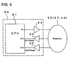
- the electric power steering device 20 is primarily composed of a steering wheel 21, a steering shaft 22, a pinion shaft 23, a rack shaft 24, a torque sensor 30, an electric motor 40, a motor resolver 44, a ball screw mechanism 50, an ECU (Electronic Control Unit) 60 and the like.
- the device 20 detects the steering state on the steering wheel 21 and assists the steering manipulation of the driver by controlling the electric motor 40 to generate an assist force depending on the steering state.
- Opposite ends of the rack shaft 24 are connected to steerable road wheels (usu., front wheels (not shown)) through tie rods and the like, respectively.
- the steering wheel 21 is connected to one end of the steering shaft 22, whose other end is connected by means of a pin 32 to an input shaft 23a of the toque sensor 30 and a torsion bar 31 which are both received in a pinion housing 25.
- the other end 31a of the torsion bar 31 is spline-connected to an output shaft 23b of the pinion shaft 23.
- the input shaft 23a and the output shaft 23b of the pinion shaft 23 are rotatably supported within the pinion housing 25 respectively through bearings 33a and 33b.
- a first resolver 35 constituting the torque sensor 30 is interposed between the input shaft 23a and the pinion housing 25, while a second resolver 37 also constituting the torque sensor 30 is interposed between the output shaft 23b and the pinion housing 25.
- the first and second resolvers 35, 37 are each capable of detecting the steering angle of the steering wheel 21 and are electrically connected to the ECU 60 through respective terminals 39, as typically shown in Figure 5 . The constructions of these resolvers 35, 37 will be described later in detail.
- a rack-and-pinion mechanism is constructed in this manner.
- the steering shaft 22 and the pinion shaft 23 are connected by means of a torsion bar 31 to be rotatable relative to each other through the torsion of the torsion bar 31, and the rotational angle of the steering shaft 22 or the rotational angle (mechanical angle) ⁇ Tm of the steering wheel 21 can be detected based on a first steering angle (electrical angle) ⁇ T1 and a second steering angle (electrical angle) ⁇ T2 which are detected respectively by the first and second resolvers 35, 37. Further, a torsional quantity (corresponding to the steering torque) can be detected as torsional angle based on the angular difference between the first steering angle ⁇ T1 and the second steering angle ⁇ T2, the ratio therebetween or the like.
- the rack shaft 24 is housed within a rack housing 26 and a motor housing 27 to pass therethrough and is formed with a male ball screw 24b at the intermediate portion thereof.
- a motor shaft 43 like a cylindrical sleeve is supported by bearings 29 to be rotatable in coaxial alignment with the rack shaft 24.
- the motor shaft 43 together with an exciting coil 42 and the like, constitutes the electric motor 40, wherein a field system that is generated by the exciting coil 42 wound around a stator 42 acts on permanent magnets 45 arranged on the external surface of the motor shaft 43 serving as a rotor, so that the motor shaft 43 can be rotated.
- the motor shaft 43 has a ball nut 52 fit on its internal surface to be rotatable bodily therewith.
- a female ball screw 52a is formed at the internal surface of the ball nut 52.
- a plurality of balls 54 are interposed between the female ball screw 52a of the ball screw nut 52 and the male ball screw 24b of the rack shaft 24. This constitutes a ball screw mechanism 50 capable of moving the rack shaft 24 in the axial direction thereof upon rotation of the motor shaft 43.
- the ball screw mechanism 50 composed of the both ball screws 24b, 52a and the like is able to convert the rotational torque in the positive-going and negative-going directions of the motor shaft 43 into the reciprocating motion of the rack shaft 24 in the axial direction thereof.
- the reciprocating motion becomes the assist force which reduces the manipulation or steering force to be exerted on the steering wheel 21, through the pinion shaft 23 constituting the rack-and-pinion mechanism together with the rack shaft 24.
- a motor resolver 44 capable of detecting the rotational angle (electrical angle) ⁇ Me of the motor shaft 43 is interposed between the motor shaft 43 of the motor 40 and the motor housing 27.
- the resolver 44 is electrically connected to the ECU 60 through terminals (not shown), as shown in Figure 5 .
- first resolver 35 the second resolver 37 and the motor resolver 44 will be described with reference to Figure 4(A) . Since these resolvers are substantially the same to one another in construction, the first resolver 35 is typically described with respect to those portions common to all the resolvers.
- the first resolver 35 is composed of a first yoke YK1, a second yoke YK2, a third yoke YK3 and a fourth yoke YK4, a first coil CL1, a second coil CL2, a third coil CL3 and a fourth coil CL4, and is of the type having five pole pairs (i.e., a so-called 5X).
- the term "the number of pole pairs" will be described later.
- the first yoke YK1 is formed as an annular cylinder encircled by the internal surface of the pinion housing 25 and is secured to the pinion housing 25.
- the first coil CL1 is wound along the internal surface of the first yoke YK1.
- the second yoke YK2 is formed also as an annular cylinder like the first yoke YK1 and is secured to the circumferential surface of the input shaft 23a of the pinion shaft 23 to face the first yoke YK1.
- the second coil CL2 is wound along the external surface of the second yoke YK2.
- the second yoke YK2 is rotatable bodily with the input shaft 23a.
- the third yoke YK3 is secured to the circumferential surface of the input shaft 23a at a position shifted axially from the second yoke YK2 and thus, is rotatable with the input shaft 23a.
- the third coil CL3 is wound on the third yoke YK3 and is electrically connected to the second coil CL2 of the second yoke YK2 in electrically parallel relation.
- the fourth yoke YK4 is formed as an annular cylinder encircled by the internal surface of the pinion housing 25 and is secured to the pinion housing 25.
- Each of the third and fourth coils CL3, CL4 is composed of two kinds of coils whose phases are shifted 90 degrees from each other, as schematically shown in Figure 5(B) .
- the second resolver 37 is constructed like the first resolver 35 except that the second yoke YK2, the third yoke YK3, the second coil CL2 and the third coil CL3 are provided on the output shaft 23b and that the number of the pole pairs is six (so-called "6X").
- the motor resolver 44 is constructed also like the first resolver 35, but is different from the same in the following respects.
- the first yoke YK1, the fourth yoke YK4, the first coil CL1 and the fourth coil YK4 are provided on the internal surface of the motor housing 27, while the second yoke YK2, the third yoke YK3, the second coil CL2 and the third coil CL3 are provided on the circumferential surface of the motor shaft 43.
- the number of the pole pairs in the motor resolver 44 is seven (so-called "7X").
- the first resolver 35 is composed of the first to fourth coils CL1-CL4 and is of the type so-called "one exciting phase, two output phases" (voltage detection type). Therefore, an exciting signal E1 which is output from an output port P0 of a CPU 61 constituting the ECU 60 is applied to the first coil CL1 and the second coil CL2 constituting a transformer, through a buffer amplifier 63 of the ECU 60 and is further applied to the third coil CL3 serving as one exciting phase. As a result, resolver output signals E2 and E3 depending on a detection angle ⁇ (electrical angle) can be obtained from the fourth coil CL4 including two output phase coils.
- the resolver output signals output from the first resolver 35 are analogue signals composed of a sine-phase signal and a cosine-phase signal, they are converted into digital signals which the CPU 61 can process, by being input into respective A-D (Analogue-to-Digital) converters incorporated in the CPU 61 through buffer amplifiers 64, 65 of the ECU 60.
- A-D Analogue-to-Digital
- the resolver output signals obtained from the first resolver 35 in this manner are converted by the CPU 61 into an electrical angle ⁇ T1 shown in Figure 6
- the resolver output signals obtained from the second resolver 37 are converted by the CPU 61 into another electrical angle ⁇ T2 shown in Figure 6 .
- the electrical angle ⁇ T1 obtained from the first resolver 35 has five (5) peak points per rotation (360 degrees) of the steering wheel 21. This is because the first resolver 35 is of the type having five pole pairs each pair of which is composed of one N-pole and one S-pole in the electrical sense, and because it can output electrical angles corresponding to 1800 degrees (360 x 5) for the 360 degree mechanical angles. In short, the first resolver 35 has a resolution of five (5) times as many as a resolver having a resolution of 360 electrical angles.
- the electrical angle ⁇ T2 obtained from the second resolver 37 has six (6) peak points per rotation (360 degrees) of the steering wheel 21. This is because the second resolver 37 is of the type having six pole pairs each pair of which is composed of one N-pole and one S-pole in the electrical sense, and because it can output electrical angles corresponding to 2160 degrees (360 x 6) for the 360 degree mechanical angles. In short, the second resolver 37 has a resolution of six (6) times as many as a resolver having a resolution of 360 electrical angles.
- the first resolver 35 outputs the electrical angle ⁇ T1 as its resolver signal while the second resolver 37 outputs the electrical angle ⁇ T2 as its resolver signal, but as understood from Figure 6 , they do not take the same value even at any angle of the steering wheel 21. Consequently, over one rotation of the steering wheel 21, a mechanical angle ⁇ Tm of a high resolution can be obtained based on the electrical angle ⁇ T1 of the first resolver 35 and the electrical angle ⁇ T2 of the second resolver 37 through the operation processing executed by the CPU 61.
- the steering torque T can be calculated from the relative rotational difference ⁇ indicating the torsion angle of the torsion bar 31 and the torsional rigidity of the torsion bar 31.
- the CPU 61 of the ECU 60 is able to control the aforementioned motor 40, so that the steering manipulation of the driver can be assisted with the steering force generated by the motor 40.
- motor rotational angle detecting the rotational angle of the motor shaft 43 (hereafter as "motor rotational angle") based on a resolver signal output from the motor resolver 44 can also be explained as follows:
- the CPU 61 composing the ECU 60 is electrically connected to each of the first and second resolvers 35, 37 and the motor resolver 44 through the buffer amplifiers 63, 64, 65. And, the first and second resolvers 35, 37 are able to detect the steering angle (electric angles ⁇ T1, ⁇ T2) of the steering wheel 21, while the motor resolver 44 is able to detect the motor rotational angle (electrical angle ⁇ Me) of the motor 40.
- absolute position detecting processing processing for detecting the absolute angular position of the steering wheel 21 (hereafter referred to as “absolute position detecting processing”) is executed based on the electrical angles ⁇ T1, ⁇ T2, ⁇ Me which are represented respectively by the resolver output signals output from the three resolvers.
- Step S101 processing for acquiring the electrical angles ⁇ T1, ⁇ T2, ⁇ Me of the resolvers 35, 37, 44 is executed at Step S101. More specifically, since the electrical angles ⁇ T1, ⁇ T2 which correspond to the steering angle of the steering wheel 21 are output from the first and second resolvers 35, 37, the resolver signals output from the first and second resolvers 35, 37 are acquired through the buffer amplifies 64, 65 and the A-D converters.
- the electrical angle ⁇ Me which corresponds to the motor rotational angle of the motor 40 is detected from the motor resolver 44, and the resolver signal output from the motor resolver 44 is acquired through the buffer amplifies 64, 65 and the A-D converters.
- Step S103 processing is executed to calculate the mechanical angle ⁇ Tm of the steering wheel 21 from the electrical angles ⁇ T1, ⁇ T2.
- the mechanical angle ⁇ Tm of the steering wheel 21 can be calculated based on the electrical angles ⁇ T1, ⁇ T2 of the two resolvers 35, 37 differing in the number of pole pairs from each other.
- This operation processing is described in detail in Japanese Patent Application No. 2002-196131 filed by the Assignee of the present application, and hence, reference is to be made to that application for details.
- symbol "r” denotes a calculation valve which is the product of the reduction gear ratio of the ball screw mechanism 50 with the number of pole pairs of the motor resolver 44, and as mentioned later, it is the essential requirement that the product is to be a non-integer with a numerical value of the decimal place.
- Step S107 processing is executed to convert the four calculated motor electrical angles ⁇ Me(A) into predetermined angular ranges. That is, in order that each of the calculated motor electrical angles ⁇ Me(A) calculated at Step S105 becomes within an angular range of 0 to 360 degrees, the electrical angles less than 0 degrees are processed to be taken as the absolute values, and the electrical angles larger than 360 degrees are processed under the calculation of " ⁇ Me(A)-INT( ⁇ Me(A) /360) x 360".
- the symbol "INT()" in this calculation stands for a function for converting the quotient within the parenthesis into an integer.
- Step S109 processing is executed to select from the four calculated motor electrical angles ⁇ Me(A) one which is closest in value to an actual motor electrical angle ⁇ Me (hereafter referred to as "real motor electric angle ⁇ Me" to be distinguished from the calculated motor electrical angles ⁇ Me(A)). That is, as mentioned later, of the four calculated motor electrical angles ⁇ Me(A) which have been obtained for the total rotations of the steering wheel 21 at Steps S105 and S109, one of them is the calculated motor electrical angle ⁇ Me(near) that properly represents the absolute position of the steering wheel 21, and therefore, the processing for selecting such one calculated motor electrical angle ⁇ Me(A) is executed at this step S109.
- the processing at this Step 109 may be modified to the processing for selecting one closest to an integer, from all the calculated motor electrical angles ⁇ Me(A) calculated through Steps S105 and S109.
- the processing for selecting one closest to the real motor electrical angle ⁇ Me detected by the motor resolver 44 is executed at this Step S109. This can be done by calculating the differences between the real motor electrical angle ⁇ Me acquired at Step S101 and all the calculated motor electrical angles ⁇ Me(A) and then, by selecting as the calculated motor electrical angle ⁇ Me(near) one corresponding to the smallest difference. In this way of selection, the algorithm for realizing the processing at Step S109 can be simplified compared to the processing for selecting one closest to an integer.
- step S111 processing is performed to judge whether or not, the calculated motor electrical angle ⁇ Me(near) which has been selected through Step S109 is really appropriate. More specifically, the calculated motor electrical angle 6Me(near) has been selected at Step S109 as one which is closest to the real motor electrical angle ⁇ Me detected by the motor resolver 44. However, in the event that the difference between the calculated motor electrical angle ⁇ Me(near) and the real motor electrical angle ⁇ Me exceeds a predetermined threshold value (e.g., 10 degrees), such a high probability can be anticipated that there has arisen an error exceeding a predetermined tolerance.
- a predetermined threshold value e.g. 10 degrees
- Such an error may be due to any one or some of the defects in dimensional accuracy of mechanical components which constitute the pinion shaft 23, the rack shaft 24, the ball screw mechanism 50 or the like, due to the abrasion or the like of the mechanical components, or due to the deterioration in temperature characteristic of semiconductor electronic components such as, for example, operational amplifiers for processing the resolver signals, or the like.
- the occurrence of the abnormality is alerted and a series of the absolute position detecting processing is terminated for the reason of the error.
- the routine proceeds to the next Step S113, wherein processing is executed to calculate an absolute steering angle ⁇ Am.
- Step 113 the parameter A indicative of the calculated motor electrical angle ⁇ Me selected at Step S109 (the index A in this particular embodiment is any of 0, 1,-1 and-2) is substituted into the following equation (4) to execute processing based on the mechanical angle ⁇ Tm of the steering wheel 21 which has been calculated at Step S103.
- the absolute steering angle ⁇ Am of the steering wheel 21 can be detected, so that the series of the absolute position detecting processing is terminated normally.
- ⁇ Am ⁇ Tm + 360 ⁇ A
- the parameter A obtained in this way can be updated or renewed. Accordingly, after the execution of the absolute position detecting processing, the absolute steering angle ⁇ Am can be calculated by the use of the equation noted above.
- updating the parameter A is executed using the following equations (4)' and (4)".
- a judgment is made as to whether or not, the angle which is obtained by subtracting the preceding mechanical angle ⁇ Tm-old from the present mechanical angle ⁇ Tm of the steering wheel 21 exceeds 180 degrees, namely whether or not, the equation (4)' below is satisfied. If the equation (4)' below is satisfied, it is meant that the steering wheel 21 has been rotated more than one rotation in the left turn.
- the parameter A can be updated appropriately, so that after the execution of the aforementioned absolute position detection processing, the absolute steering angle ⁇ Am can be calculated using the equation (4) above.
- the Assignee of the present application has represented a steering angle detected by the torque sensor 30 as symbol ⁇ t (corresponding to the aforementioned mechanical angle ⁇ Tm), an electrical angle of the motor rotational angle as symbol ⁇ m (corresponding to the aforementioned real motor electrical angle ⁇ Me), the absolute position Pt of the steering wheel 21 detected by a torque sensor as an equation (5) below, and the absolute position Pm of the steering wheel 21 detected from the motor rotational angle as an equation (6) below.
- the calculated value (r) is the product of the reduction gear ratio of the ball screw mechanism 50 with the number of pole pairs in the motor resolver 44.
- Pt ⁇ t + 360 ⁇ A
- Pm ⁇ m + 360 ⁇ B / r
- the parameter A is an integer taking one of - 2, -1, 0, 1.
- the parameter B becomes an integer within the range of -126 through 125 in the case that theoretically, there does not arise any error which is caused by the shaking or jolting in the mechanical system connecting the steering wheel 21 with the motor 40 or by the error in the absolute accuracy of the electrical angle of the first and second resolvers 35, 37 constituting the torque sensor 30 or of the motor resolver 44 of the motor 40.
- the time interval Tm1 at which the resolver 44 outputs its detection signal ⁇ m is set as 7 cycles which corresponds to the number of the pole pairs of the motor resolver 44
- the parameter B is the value which is given theoretically as an integer. Actually, however, there are involved some errors due to the shaking in the mechanical system connecting the steering wheel 21 with the motor 40, or due to errors in absolute accuracy of the electrical angles which are detected by the first and second resolvers 35, 37 of the torque sensor 30 and the motor resolver 44 of the motor 40.
- the parameter B includes a value of the decimal place and since four kinds of the B-parameters can be obtained from the equation (8) above in dependence on the values of the parameter A (i.e., -2, -1, 0, 1), a case may occur that in selecting one appropriate value (i.e., true value) as the absolute position of the steering wheel 21, such one appropriate value is confused with other three values (i.e., false values).
- the processing is executed to select the parameter B which of all the B-parameters, is closest to an integer.
- any of the three other values i.e., false values
- the appropriate value i.e., true value
- the calculated value (r) is the product of the reduction gear ratio of the ball screw mechanism 50 with the number of pole pairs in the motor resolver 44.
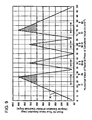
- Figure 9 is a characteristic chart which shows the variation of the room for the true value detection in connection with numerical values of the decimal place of the calculated value (r). The grounds of this characteristic chart will be described later.
- the difference between the true value ⁇ b and the false value ⁇ b closest to the true value ⁇ b is 20 degrees for example.
- the room for the true value detection corresponds to "angular deviation from the motor electrical angle" defined in the patent claims.
- the error due to the shaking of the mechanical system is ⁇ 0.24 degrees and that the detection accuracy of the torque sensor 30 is ⁇ 0.16 degrees
- the error of the mechanical angle ⁇ Tm of the steering wheel 21 which are calculated from the electrical angles ⁇ T1, ⁇ T2 as mentioned previously becomes 0.4 degrees as the sum thereof.
- the error becomes 48.6 degrees which the twice of the 24.3 degrees.
- Step S111 it is judged at Step S111 for the absolute position detecting processing whether or not, the difference between the calculated motor electrical angle ⁇ Me(near) and the real motor electrical angle ⁇ Me exceeds the predetermined threshold value (e.g., 10 degrees), and if it exceeds the predetermined threshold value, the routine under processing is terminated for the reason of abnormality (ERROR).
- the added value of 60 degrees which is made by adding the predetermined threshold value (e.g., 10 degrees) to the error zone boundary (i.e., 50 degrees) can be set as a lower limit value for the angular deviation from the calculated motor electrical angle ⁇ Me(A).
- a room (i.e., 60 degrees) for the true value detection calculated in this manner is also shown as a broken line in Figure 9 .
- the true value can be selected from the plural calculated motor electrical angles ⁇ Me(A) without being confused with other false values at the foregoing Step S109 even in the presence of the error due to the shaking in the mechanical system constituting the electric power steering device 20.
- the room of 60.0 to 90 degrees for the true value detection corresponds to 67% or more and 100% or less of the zigzag line K which represents the variation of the room for the true value detection in relation to the variation in the numerical value of the decimal place of the calculated value (r).
- the numerical value of the decimal place of the calculated value (r) within this zone are within one of ranges "from 0.17 to 0.28", "from 0.39 to 0.42", "from 0.58 to 0.61" and "from 0.72 to 0.83", as extracted from Figure 9 .
- Figure 10(A) shows the characteristic representing the variation of the deviations from the calculated motor electrical angle ⁇ Me(-2) in relation to the numerical values of the decimal place of the calculated value (r).
- the zone e.g., oblique line zone
- 60.0 to 90.0 degrees on the zigzag line K shown in Figure 9 can be applied as it is.
- the reduction gear ratio of the ball screw mechanism 50 is set so that the calculated value (r) which is the product of the reduction gear ratio with the number of pole pairs of the motor resolver 44 becomes a non-integer having a numerical value of the decimal place.
- the calculated value (r) has a zero value as the numerical value less that the decimal point or does not become an integer.
- the absolute position ⁇ Am of the steering wheel 21 can be precisely detected at Step S109 for the absolute position detecting processing executed by the CPU 61 of the ECU 60.
- the motor 40 for assisting the steering manipulation can be controlled by the ECU 60 in dependence on the absolute steering angle ⁇ Am of the steering wheel 21 which is detected in the manner mentioned above.
- the absolute position ⁇ Am of the steering wheel 21 can be precisely detected at Step S109 for the absolute position detecting processing executed by the CPU 61 of the ECU 60. Accordingly, like the case that the reduction gear ratio of the ball screw mechanism 50 is so set, the motor 40 for assisting the steering manipulation can be controlled by the ECU 60 in dependence on the absolute steering angle ⁇ Am of the steering wheel 21.
- the absolute steering angle ⁇ Am of the steering wheel 21 can be detected precisely, so that the ECU 60 is able to control the motor 40 for assisting the steering manipulation, based on the absolute steering angle ⁇ Am of the steering wheel 21 so precisely detected.
- the numerical ranges are for example "0.17 to 0.28", “0.39 to 0.42", "0.58 to 0.61" and "0.72 to 0.83".
- the absolute steering angle ⁇ Am of the steering wheel 21 can be detected precisely, so that the ECU 60 is able to control the motor 40 for assisting the steering manipulation, in dependence on the absolute steering angle ⁇ Am of the steering wheel 21 so precisely detected.
- the step or means for setting the numerical value of the decimal place of the calculated value (r) to one of, e.g., 0.17 to 0.28", “0.39 to 0.42", “0.58 to 0.61” and “0.72 to 0.83” may be replaced by means for setting the reduction gear ratio of the ball screw mechanism 50 by the following equations (9) and (10).
- the steering wheel 21 are rotated two rotations to the left and two rotations to the left and hence, four rotations in total.
- the present invention is not limited to the example as taken in the foregoing embodiment.
- the steering wheel is capable of rotating two rotations or more, the same technological functions and the effects can be obtained, for example, when it is rotated two rotations in total including one to the left and one to the right, when it is rotated six rotations including three to the left and three to the right, or when it Is rotated three rotations including 1.5 to the left and 1.5 to the right.
- the numerical value of the decimal place of the calculated value (r) is within the predetermined range. That is, the numerical value of the decimal place of the calculated value (r) which is obtained by multiplying the reduction gear ration of the reduction gear mechanism with the number of the pole pairs of the third resolver 44 is within the predetermined range.
- the numerical value of of the decimal place of the calculated value (r) is within one of the predetermined ranges.
- This predetermine ranges are numerical ranges of the decimal place which cause those angular deviations corresponding in value to 67% to 100% of the largest one of the angular deviations from the motor electrical angles which deviations are different for the respective rotational range units including at lest one left rotation and one right rotation of said steering wheel.
- the expression "67% to 100% of the largest one of the angular deviations" can be explained by the aforementioned zigzag line K shown in Figure 9 for example and means the oblique-line zones in Figure 9 each of which is within the range of 67% to 100% (60 to 90 degrees) of the largest value (90 degrees) of the zigzag line K.
- the step of and means for setting at least one of the reduction gear ratio of the reduction gear mechanism and the number of pole pairs of the third resolver 44 is so set that the calculated value (r) which is obtained by multiplying the reduction gear ratio with the number of pole pairs of the third resolver 44 represents a non-integer having one of "0.17 to 0.28", “0.39 to 0.42", "0.58 to 0,61” and "0.72 to 0.83" as the numerical value of the decimal place thereof.
- the numerical value of the decimal place of such a calculated value (r) is within one of numerical ranges of the decimal place which cause those angular deviations corresponding in value to 67% to 100% of the largest one of angular deviations from the motor electrical angles ⁇ Me.
- the numerical ranges of the decimal place are represented as "0.17 to 0.28", “0.39 to 0.42", "0.58 to 0.61” and "0.72 to 0.83".
- the absolute position of the steering wheel 21 can be detected precisely, so that the method and apparatus can be obtained for manufacturing the electric power steering device 20 which is capable of controlling the motor 40 for assisting the steering manipulation reliably in dependence on the absolute value of the steering wheel 21 so precisely detected.
- An electric power steering device employs, in addition to a motor resolver of an electric motor for assisting the rotational manipulation of a steering shaft, first and second resolvers which are made different in the number of N-S pole pairs from each other each for detecting the rotational position of the steering shaft.
- the reduction gear ratio of a reduction gear mechanism of a ball screw mechanism driven by the electric motor is set so that a calculated value which is obtained by multiplying the reduction gear ratio with the number of pole pairs of a motor resolver represents a non-integer having a numerical value of the decimal place. Thus, it does not occur that calculated value becomes an integer which does not have any numerical value of the decimal place.
- the mechanical angle of the steering wheel which is calculated based on electrical angles of the first and second resolvers can be made not take the same value within any one-rotational range unit as that within another one-rotational range unit of four rotations in total of the steering wheel including two left rotations and two right rotations. Consequently, it becomes possible to detect the absolute rotational position of the steering wheel precisely, so that the motor for assisting the steering manipulation can reliably be controlled in dependence on the absolute rotational position of the steering wheel so precisely detected.
Claims (3)
- Dispositif de direction assistée électrique ayant
un volant de direction (21) ;
un premier résolveur (35) destiné à détecter un premier angle de braquage (θT1) indiquant l'angle de rotation d'un arbre de direction (22) connecté audit volant de direction ;
un deuxième résolveur (37) ayant des paires de pôles dont le nombre est différent de celui dudit premier résolveur destiné à détecter un deuxième angle de braquage (θT2) indiquant l'angle de rotation dudit arbre de direction ;
un moteur électrique (40) destiné à faciliter l'opération de direction effectuée par un mécanisme de direction connecté audit arbre de direction, grâce à un mécanisme à engrenage de réduction (50) ; et
un troisième résolveur (44) destiné à détecter un angle électrique de moteur (θMe) indiquant l'angle de rotation dudit moteur électrique, ledit dispositif de direction assistée électrique étant capable de commander ledit moteur électrique sur la base de la position de rotation dudit volant de direction qui est calculée sur la base desdits premier et deuxième angles de braquage et dudit angle électrique de moteur, dans lequel :au moins l'un du rapport d'engrenage de réduction dudit mécanisme à engrenage de réduction et du nombre de paires de pôles dudit troisième résolveur est réglé de sorte qu'une valeur calculée qui est obtenue en multipliant ledit rapport d'engrenage de réduction par ledit nombre desdites paires de pôles représente un nombre non entier ayant une valeur numérique de la décimale dans l'une des plages numériques « 0,17 à 0,28 », « 0,39 à 0,42 », « 0,58 à 0,61 » et « 0,72 à 0,83 ». - Dispositif selon la revendication 1, dans lequel lesdites plages numériques de la décimale provoquent des écarts angulaires correspondant en valeur à 67 % à 100 % du plus grand des écarts angulaires à partir desdits angles électriques de moteur, lesquels écarts sont différents pour les unités de plage de rotation respectives comprenant au moins une rotation à gauche et une rotation à droite dudit volant de direction.
- Procédé de fabrication d'un dispositif de direction assistée électrique, comprenant les étapes consistant à
fabriquer un dispositif de direction assistée électrique ayant un volant de direction (21) ; un premier résolveur (35) destiné à détecter un premier angle de braquage (θT1) indiquant l'angle de rotation d'un arbre de direction connecté audit volant de direction (22) ; un deuxième résolveur (37) ayant des paires de pôles dont le nombre est différent de celui dudit premier résolveur destiné à détecter un deuxième angle de braquage (θT2) indiquant l'angle de rotation dudit arbre de direction ; un moteur électrique (40) destiné à faciliter l'opération de direction effectuée par un mécanisme de direction connecté audit arbre de direction, grâce à un mécanisme à engrenage de réduction (50) ; et un troisième résolveur (44) destiné à détecter un angle électrique de moteur (θMe) indiquant l'angle de rotation dudit moteur électrique ; ledit dispositif de direction assistée électrique étant capable de commander ledit moteur électrique sur la base de la position de rotation absolue dudit volant de direction qui est calculée à partir desdits premier et deuxième angles de braquage et dudit angle électrique de moteur,
ledit procédé comprenant l'étape consistant à régler au moins l'un dudit rapport d'engrenage de réduction dudit mécanisme à engrenage de réduction et du nombre de paires de pôles dudit troisième résolveur de sorte qu'une valeur calculée qui est obtenue en multipliant ledit rapport d'engrenage de réduction par ledit nombre de paires de pôles dudit troisième résolveur représente un nombre non entier qui a une valeur numérique de la décimale dans l'une des plages numériques « 0,17 à 0,28 », « 0,39 à 0,42 », « 0,58 à 0,61 » et « 0,72 à 0,83 ».
Applications Claiming Priority (2)
| Application Number | Priority Date | Filing Date | Title |
|---|---|---|---|
| JP2002309252 | 2002-10-24 | ||
| JP2002309252 | 2002-10-24 |
Publications (2)
| Publication Number | Publication Date |
|---|---|
| EP1413499A1 EP1413499A1 (fr) | 2004-04-28 |
| EP1413499B1 true EP1413499B1 (fr) | 2008-02-13 |
Family
ID=32064353
Family Applications (1)
| Application Number | Title | Priority Date | Filing Date |
|---|---|---|---|
| EP03024469A Expired - Fee Related EP1413499B1 (fr) | 2002-10-24 | 2003-10-23 | Capteur d'angle de direction pour un dispositif de direction assistée |
Country Status (3)
| Country | Link |
|---|---|
| US (1) | US6994181B2 (fr) |
| EP (1) | EP1413499B1 (fr) |
| DE (1) | DE60319045T2 (fr) |
Families Citing this family (18)
| Publication number | Priority date | Publication date | Assignee | Title |
|---|---|---|---|---|
| JP4042049B2 (ja) * | 2003-04-16 | 2008-02-06 | 株式会社ジェイテクト | 電動パワーステアリング装置の操舵角検出装置 |
| JP4604551B2 (ja) * | 2003-09-24 | 2011-01-05 | 株式会社ジェイテクト | レゾルバ信号の演算処理方法および演算処理装置 |
| DE602004004240T2 (de) * | 2004-03-10 | 2007-07-12 | Umbra Cuscinetti S.P.A. | Lenkeinheit für ein Elektrofahrzeug |
| DE102004046946B4 (de) * | 2004-09-28 | 2013-10-02 | Trw Automotive Gmbh | Verfahren zur Montage eines Lenkwinkel- und Lenkmomentsensors sowie Lenkgetriebe mit einem Lenkwinkel- und Lenkmomentsensor |
| US7325646B2 (en) * | 2005-07-15 | 2008-02-05 | Jtekt Corporation | Electric power steering apparatus |
| RU2278797C1 (ru) * | 2005-08-19 | 2006-06-27 | Открытое акционерное общество "Калужский завод электронных изделий" | Электромеханический усилитель руля автомобиля и электродвигатель для усилителя руля |
| WO2007139868A2 (fr) * | 2006-05-24 | 2007-12-06 | Tt Electronics Technology Limited | Détecteur de rotation multitours |
| EP1879087A3 (fr) * | 2006-07-10 | 2010-08-18 | Brose Schliesssysteme GmbH & Co. KG | Dispositif de détection de position pour un élément fonctionnel déplaçable et motorisé dans un véhicule |
| DE102007027041B4 (de) * | 2006-07-13 | 2015-01-15 | Ford Global Technologies, Llc | Verfahren zur Ermittlung eines Drehmomentes an einem Lenkungsstrang |
| EP1892172B1 (fr) * | 2006-08-21 | 2009-09-16 | JTEKT Corporation | Dispositif de direction |
| EP1990256B1 (fr) * | 2007-05-08 | 2011-06-15 | Jtekt Corporation | Dispositif de direction assistée électrique |
| JP4863953B2 (ja) * | 2007-08-30 | 2012-01-25 | 日立オートモティブシステムズ株式会社 | 物理量変換センサ及びそれを用いたモータ制御システム |
| KR101450320B1 (ko) * | 2010-04-20 | 2014-10-21 | 주식회사 만도 | 볼감속기를 구비한 랙구동형 전동식 조향장치 |
| KR101450322B1 (ko) * | 2011-01-31 | 2014-10-21 | 주식회사 만도 | 볼감속기를 구비한 랙구동형 전동식 조향장치 |
| WO2013175729A1 (fr) | 2012-05-22 | 2013-11-28 | 日本精工株式会社 | Dispositif de détection d'angle de direction de véhicule et dispositif de direction assistée électrique |
| SE538475C2 (en) * | 2014-03-28 | 2016-07-19 | Allied Motion Stockholm Ab | Method for deriving an absolute multiturn rotational angle of a rotating shaft, and a device therefore |
| FR3039491B1 (fr) * | 2015-07-31 | 2017-08-11 | Jtekt Europe Sas | Dispositif de direction assistee avec coque de protection etanche |
| CN106926894A (zh) * | 2015-12-31 | 2017-07-07 | 罗伯特·博世有限公司 | 方向盘转动信息确定装置和方向盘转动信息确定方法 |
Citations (3)
| Publication number | Priority date | Publication date | Assignee | Title |
|---|---|---|---|---|
| EP1020344A1 (fr) * | 1999-01-15 | 2000-07-19 | TRW LucasVarity Electric Steering Limited | Mécanisme de direction à assistence électrique |
| DE19941101A1 (de) * | 1999-08-30 | 2001-03-01 | Delphi Tech Inc | Sensoranordnung |
| EP1291264A2 (fr) * | 2001-09-05 | 2003-03-12 | Toyoda Koki Kabushiki Kaisha | Dispositif et procédé de mesure de position absolue |
Family Cites Families (21)
| Publication number | Priority date | Publication date | Assignee | Title |
|---|---|---|---|---|
| JPS59226806A (ja) | 1983-06-08 | 1984-12-20 | Fanuc Ltd | 絶対位置検出装置 |
| JPH037673A (ja) | 1989-05-24 | 1991-01-14 | Mitsubishi Electric Corp | モータ駆動式前後輪操舵装置 |
| US5202614A (en) * | 1989-09-25 | 1993-04-13 | Silicon Systems, Inc. | Self-commutating, back-emf sensing, brushless dc motor controller |
| US5072166A (en) | 1990-06-18 | 1991-12-10 | The Texas A&M University System | Position sensor elimination technique for the switched reluctance motor drive |
| US5028852A (en) * | 1990-06-21 | 1991-07-02 | Seagate Technology, Inc. | Position detection for a brushless DC motor without hall effect devices using a time differential method |
| US5254914A (en) * | 1990-06-29 | 1993-10-19 | Seagate Technology, Inc. | Position detection for a brushless DC motor without Hall effect devices using a mutual inductance detection method |
| JPH072135A (ja) | 1993-06-17 | 1995-01-06 | Toyota Motor Corp | 電動式パワーステアリング装置 |
| JP3095961B2 (ja) | 1994-10-04 | 2000-10-10 | 本田技研工業株式会社 | 車両用操舵装置の操舵反力制御装置 |
| EP0710600B1 (fr) | 1994-11-04 | 2001-10-24 | Trw Inc. | Procédé et appareil pour contrôler un moteur électrique |
| DE19506938A1 (de) | 1995-02-28 | 1996-08-29 | Bosch Gmbh Robert | Verfahren und Vorrichtung zur Winkelmessung bei einem drehbaren Körper |
| JP3218950B2 (ja) | 1995-12-11 | 2001-10-15 | トヨタ自動車株式会社 | 車両用操舵制御装置 |
| US5786754A (en) | 1995-12-13 | 1998-07-28 | Trw Inc. | Method and apparatus for electronically cancelling a vehicle direction signal in an electric assist steering system |
| US5880367A (en) * | 1996-07-11 | 1999-03-09 | First Inertia Switch Limited | Vehicle steering sensor device |
| DE19712869A1 (de) * | 1997-03-27 | 1998-10-01 | Itt Mfg Enterprises Inc | Lenkwinkelsensorsystem mit erhöhter Redundanz |
| GB9716658D0 (en) | 1997-08-07 | 1997-10-15 | Lucas Ind Plc | Improvements relating to motors |
| GB9902438D0 (en) | 1999-02-05 | 1999-03-24 | Trw Lucas Varity Electric | Improvements relating to electric power assisted steering assemblies |
| US6519549B1 (en) | 2000-07-31 | 2003-02-11 | Delphi Technologies, Inc. | Method and device for determining absolute angular position of a rotating body |
| DE10048911C1 (de) * | 2000-10-02 | 2002-04-25 | Ruf Electronics Gmbh | Verfahren und Vorrichtung zur Bestimmung der Absolutposition bei Weg- und Winkelgebern |
| US6469499B2 (en) * | 2001-02-06 | 2002-10-22 | Delphi Technologies, Inc. | Apparatus and method for low power position sensing systems |
| JP2003329524A (ja) * | 2002-05-13 | 2003-11-19 | Koyo Seiko Co Ltd | トルク検出装置 |
| JP4042049B2 (ja) * | 2003-04-16 | 2008-02-06 | 株式会社ジェイテクト | 電動パワーステアリング装置の操舵角検出装置 |
-
2003
- 2003-10-23 EP EP03024469A patent/EP1413499B1/fr not_active Expired - Fee Related
- 2003-10-23 DE DE60319045T patent/DE60319045T2/de not_active Expired - Lifetime
- 2003-10-24 US US10/691,543 patent/US6994181B2/en not_active Expired - Lifetime
Patent Citations (3)
| Publication number | Priority date | Publication date | Assignee | Title |
|---|---|---|---|---|
| EP1020344A1 (fr) * | 1999-01-15 | 2000-07-19 | TRW LucasVarity Electric Steering Limited | Mécanisme de direction à assistence électrique |
| DE19941101A1 (de) * | 1999-08-30 | 2001-03-01 | Delphi Tech Inc | Sensoranordnung |
| EP1291264A2 (fr) * | 2001-09-05 | 2003-03-12 | Toyoda Koki Kabushiki Kaisha | Dispositif et procédé de mesure de position absolue |
Also Published As
| Publication number | Publication date |
|---|---|
| DE60319045T2 (de) | 2009-02-05 |
| US6994181B2 (en) | 2006-02-07 |
| US20050016789A1 (en) | 2005-01-27 |
| DE60319045D1 (de) | 2008-03-27 |
| EP1413499A1 (fr) | 2004-04-28 |
Similar Documents
| Publication | Publication Date | Title |
|---|---|---|
| EP1413499B1 (fr) | Capteur d'angle de direction pour un dispositif de direction assistée | |
| US7325646B2 (en) | Electric power steering apparatus | |
| EP1462340B1 (fr) | Direction assistée électrique | |
| EP2159548A2 (fr) | Unité de détection d'anomalies pour résolveur et appareil à direction assistée électrique | |
| EP1468900B1 (fr) | Direction de véhicule | |
| US20030046012A1 (en) | Apparatus and method for detecting absolute position | |
| EP2078661B1 (fr) | Système de direction pour véhicule | |
| US20050230179A1 (en) | Vehicle steering apparatus | |
| EP1516799B1 (fr) | Direction assistée électrique et procédé pour compenser l'angle correspondant | |
| JP3969220B2 (ja) | 電動パワーステアリング装置の絶対位置検出装置及び絶対位置検出方法 | |
| EP1197725A2 (fr) | Appareil pour détecter l'angle de rotation, palpeur de moment de force et appareil de commande | |
| EP1910155B1 (fr) | Appareil de détection d'angle de direction et procédé associé | |
| EP1519174B1 (fr) | Procédé et dispositif de traitement du signal d'un résolveur | |
| EP1462341B1 (fr) | Procédé pour définir un paramètre de contrôle, dispositif pour définir un paramètre de contrôle, et direction assistée électrique | |
| EP1462786B1 (fr) | Capteur de couple et direction assistée électrique utilisant ce capteur | |
| EP1586864B1 (fr) | Dispositif de mesure de l'angle de rotation et direction assistée electrique | |
| JP5311102B2 (ja) | 車両用操舵装置 | |
| US6935194B2 (en) | Dual resolver device | |
| JP4020013B2 (ja) | 車両用操舵装置 | |
| JP3875202B2 (ja) | 電気式動力舵取装置、その製造方法および製造装置 | |
| JP4438386B2 (ja) | トルク検出装置 | |
| JP2005098781A (ja) | トルクセンサの故障検出方法、トルクセンサの故障検出装置 | |
| JP7192822B2 (ja) | 操舵角推定装置、操舵装置及び、操舵角推定方法 | |
| JP2007155641A (ja) | レゾルバ装置及びそれを用いたトルクセンサ |
Legal Events
| Date | Code | Title | Description |
|---|---|---|---|
| PUAI | Public reference made under article 153(3) epc to a published international application that has entered the european phase |
Free format text: ORIGINAL CODE: 0009012 |
|
| AK | Designated contracting states |
Kind code of ref document: A1 Designated state(s): AT BE BG CH CY CZ DE DK EE ES FI FR GB GR HU IE IT LI LU MC NL PT RO SE SI SK TR |
|
| AX | Request for extension of the european patent |
Extension state: AL LT LV MK |
|
| 17P | Request for examination filed |
Effective date: 20040914 |
|
| AKX | Designation fees paid |
Designated state(s): DE FR GB |
|
| RAP1 | Party data changed (applicant data changed or rights of an application transferred) |
Owner name: JTEKT CORPORATION |
|
| RIN1 | Information on inventor provided before grant (corrected) |
Inventor name: ASADA, ATSUHISA |
|
| GRAP | Despatch of communication of intention to grant a patent |
Free format text: ORIGINAL CODE: EPIDOSNIGR1 |
|
| GRAS | Grant fee paid |
Free format text: ORIGINAL CODE: EPIDOSNIGR3 |
|
| GRAA | (expected) grant |
Free format text: ORIGINAL CODE: 0009210 |
|
| AK | Designated contracting states |
Kind code of ref document: B1 Designated state(s): DE FR GB |
|
| REG | Reference to a national code |
Ref country code: GB Ref legal event code: FG4D |
|
| REF | Corresponds to: |
Ref document number: 60319045 Country of ref document: DE Date of ref document: 20080327 Kind code of ref document: P |
|
| ET | Fr: translation filed | ||
| PLBE | No opposition filed within time limit |
Free format text: ORIGINAL CODE: 0009261 |
|
| STAA | Information on the status of an ep patent application or granted ep patent |
Free format text: STATUS: NO OPPOSITION FILED WITHIN TIME LIMIT |
|
| 26N | No opposition filed |
Effective date: 20081114 |
|
| PGFP | Annual fee paid to national office [announced via postgrant information from national office to epo] |
Ref country code: GB Payment date: 20081022 Year of fee payment: 6 |
|
| PG25 | Lapsed in a contracting state [announced via postgrant information from national office to epo] |
Ref country code: GB Free format text: LAPSE BECAUSE OF NON-PAYMENT OF DUE FEES Effective date: 20091023 |
|
| REG | Reference to a national code |
Ref country code: FR Ref legal event code: PLFP Year of fee payment: 14 |
|
| REG | Reference to a national code |
Ref country code: FR Ref legal event code: PLFP Year of fee payment: 15 |
|
| REG | Reference to a national code |
Ref country code: FR Ref legal event code: PLFP Year of fee payment: 16 |
|
| PGFP | Annual fee paid to national office [announced via postgrant information from national office to epo] |
Ref country code: FR Payment date: 20200914 Year of fee payment: 18 |
|
| PGFP | Annual fee paid to national office [announced via postgrant information from national office to epo] |
Ref country code: DE Payment date: 20201013 Year of fee payment: 18 |
|
| REG | Reference to a national code |
Ref country code: DE Ref legal event code: R119 Ref document number: 60319045 Country of ref document: DE |
|
| PG25 | Lapsed in a contracting state [announced via postgrant information from national office to epo] |
Ref country code: DE Free format text: LAPSE BECAUSE OF NON-PAYMENT OF DUE FEES Effective date: 20220503 |
|
| PG25 | Lapsed in a contracting state [announced via postgrant information from national office to epo] |
Ref country code: FR Free format text: LAPSE BECAUSE OF NON-PAYMENT OF DUE FEES Effective date: 20211031 |