EP1413499B1 - Steering angle sensor arrangement for an electric power steering device - Google Patents
Steering angle sensor arrangement for an electric power steering device Download PDFInfo
- Publication number
- EP1413499B1 EP1413499B1 EP03024469A EP03024469A EP1413499B1 EP 1413499 B1 EP1413499 B1 EP 1413499B1 EP 03024469 A EP03024469 A EP 03024469A EP 03024469 A EP03024469 A EP 03024469A EP 1413499 B1 EP1413499 B1 EP 1413499B1
- Authority
- EP
- European Patent Office
- Prior art keywords
- steering
- resolver
- angle
- motor
- steering wheel
- Prior art date
- Legal status (The legal status is an assumption and is not a legal conclusion. Google has not performed a legal analysis and makes no representation as to the accuracy of the status listed.)
- Expired - Fee Related
Links
Images


Classifications
-
- B—PERFORMING OPERATIONS; TRANSPORTING
- B62—LAND VEHICLES FOR TRAVELLING OTHERWISE THAN ON RAILS
- B62D—MOTOR VEHICLES; TRAILERS
- B62D15/00—Steering not otherwise provided for
- B62D15/02—Steering position indicators ; Steering position determination; Steering aids
-
- G—PHYSICS
- G01—MEASURING; TESTING
- G01D—MEASURING NOT SPECIALLY ADAPTED FOR A SPECIFIC VARIABLE; ARRANGEMENTS FOR MEASURING TWO OR MORE VARIABLES NOT COVERED IN A SINGLE OTHER SUBCLASS; TARIFF METERING APPARATUS; MEASURING OR TESTING NOT OTHERWISE PROVIDED FOR
- G01D2205/00—Indexing scheme relating to details of means for transferring or converting the output of a sensing member
- G01D2205/20—Detecting rotary movement
- G01D2205/26—Details of encoders or position sensors specially adapted to detect rotation beyond a full turn of 360°, e.g. multi-rotation
-
- G—PHYSICS
- G01—MEASURING; TESTING
- G01D—MEASURING NOT SPECIALLY ADAPTED FOR A SPECIFIC VARIABLE; ARRANGEMENTS FOR MEASURING TWO OR MORE VARIABLES NOT COVERED IN A SINGLE OTHER SUBCLASS; TARIFF METERING APPARATUS; MEASURING OR TESTING NOT OTHERWISE PROVIDED FOR
- G01D2205/00—Indexing scheme relating to details of means for transferring or converting the output of a sensing member
- G01D2205/20—Detecting rotary movement
- G01D2205/28—The target being driven in rotation by additional gears
Definitions
- the present invention relates to an electric power steering device for employing an electric motor to assisting the steering force applied to road wheels. It further relates a method and apparatus for manufacturing the electric power steering device.
- a steering mechanism connected to a steering shaft is given an assist force generated by an electric motor thereby to reduce the steering force to be applied to a steering wheel.
- the steering wheel is rotated more than one full turn to the left and more than one full turn to the right within a limited rotational range.
- a neutral position of the steering wheel is assumed to be "the position that the steering wheel takes while the vehicle runs straight ahead", and a steering angle is grasped by detecting as an absolute position the position to which the steering wheel is turned from the neutral position to the left or right.
- the steering angle of the steering wheel is usually detected by the use of a rotary angle sensor which is composed of, e.g., a slit disc rotating with the steering shaft and a photo interrupter.
- a rotary angle sensor which is composed of, e.g., a slit disc rotating with the steering shaft and a photo interrupter.
- steering wheels of vehicles are generally of the construction that the angle of steered wheels (usu., front wheels) over the whole range cannot be controlled through the steering within one rotation (360 degrees).
- the steering wheel is capable of varying its steering angle as desired within a predetermined angular range by rotating the steering wheel through 720 degrees toward the plus side or the minus side.
- the same construction is taken as "the steering sensor and the power steering device" disclosed in the aforementioned Japanese application, it is impossible to detect the absolute rotational position of the steering wheel in addition to the rotational angle thereof by the use of one rotary angle sensor.
- Another electric power steering device has also been known, wherein there are employed a resolver as means for detecting the rotational position of an electric motor which generates the assisting force and another resolver as means for detecting the steering torque generated by a steering wheel.
- a resolver as means for detecting the rotational position of an electric motor which generates the assisting force
- another resolver as means for detecting the steering torque generated by a steering wheel.
- Document EP 1 026 068 A2 discloses an electric power assistance steering system, in which two sensors, which may be resolvers, are provided, of which one sensor (9) senses the angular position of a motor rotor and the other (10) senses the angular position of a steering shaft connected to wheels
- EP 1 026 068 A2 describes the use of a non-integer gear ratio for a gear box (7) connecting the steering shaft and the motor 6, which serves to provide a "beat" frequency between the outputs of the two sensors is described in more detail.
- Document DE 1997 12 869 A discloses a steering angle sensor system in which two sensors are used in order to enhance redundancy.
- DE 1997 12 869 A suggests using sensors having different performances in order to reduce costs. According to this document, it is sufficient to have only one sensor comprising the necessary resolution for detecting an angle, whereas it is sufficient for the other sensor to provide a coarser resolution.
- sensors operating with different measurement methods for example, using a resolver having pole-pairs (as in the present application) and an optical encoder using CCD technology.
- Another object of the present invention is to provide an improved method and apparatus for manufacturing an electric power steering device which is capable of precisely detecting the absolute rotational position of a steering wheel even under the condition of error factors being involved therein, so that there can be manufactured an electric power steering device which can be operated reliably in dependence on the absolute rotational position of the steering wheel so precisely detected.
- an electric power steering device which comprises a steering wheel, a first resolver for detecting a first steering angle indicating the rotational angle of a steering shaft connected to the steering wheel, and a second resolver having pole pairs different in number from those of the first resolver for detecting a second steering angle indicating the rotational angle of the steering shaft.
- the electric power steering device further comprises an electric motor for assisting the steering operation performed by a steering mechanism connected to the steering shaft, through a reduction gear mechanism, and a third resolver for detecting a motor electrical angle indicating the rotational angle of the electric motor.
- the electric power steering device is capable of controlling the electric motor based on the absolute rotational position of the steering wheel which is calculated from the first and second steering angles and the motor electrical angle. And, at least one of the reduction gear ratio of the reduction gear mechanism and the number of pole pairs of the third resolver is set so that a calculated value which is obtained by multiplying the reduction gear ratio with the number of the pole pairs represents a non-integer having a numerical value of the decimal place.
- the expression "pole pairs” means the gathering of plural pairs each pair of which comprise one N-pole and one S-pole.
- the calculated value which Is obtained by multiplying the reduction gear ratio with the number of the pole pairs represents a non-integer having a numerical value of the decimal place
- the calculated value becomes an integer.
- the steering angle (0 to 360 degrees) within one revolution of the steering wheel which is obtained from the first steering angle of the first resolver and the second steering angle of the second resolver can be made not take the same value within any one-rotational range unit as that within another one-rotational range unit of the plural left and right rotations of the steering wheel. Consequently, it becomes possible to detect the absolute rotational position of the steering wheel precisely, so that the motor for assisting the steering manipulation can reliably be controlled in dependence on the absolute rotational position of the steering wheel so precisely detected.
- a method of manufacturing an electric power steering device comprising a steering wheel, a first resolver for detecting a first steering angle indicating the rotational angle of a steering shaft connected to the steering wheel, a second resolver having pole pairs different in number from those of the first resolver for detecting a second steering angle indicating the rotational angle of the steering shaft, an electric motor for assisting the steering operation performed by a steering mechanism connected to the steering shaft, through a reduction gear mechanism, and a third resolver for detecting a motor electrical angle indicating the rotational angle of the electric motor.
- the electric power steering device is capable of controlling the electric motor based on the absolute rotational position of the steering wheel which is calculated from the first and second steering angles and the motor electrical angle.
- the method of manufacturing the electric power steering device as constructed above includes the step of setting at least one of the reduction gear ratio of the reduction gear mechanism and the number of pole pairs of the third resolver so that a calculated value which is obtained by multiplying the reduction gear ratio with the number of the pole pairs of the third resolver represents a non-integer which has a numerical value of the decimal place within one of numerical ranges "0.17 to 0.28", “0.39 to 0.42", "0.58 to 0.61" and "0.72 to 0.83".
- an apparatus for manufacturing an electric power steering device comprising a steering wheel, a first resolver for detecting a first steering angle indicating the rotational angle of a steering shaft connected to the steering wheel, a second resolver having pole pairs different in number from those of the first resolver for detecting a second steering angle indicating the rotational angle of the steering shaft, an electric motor for assisting the steering operation performed by a steering mechanism connected to the steering shaft, through a reduction gear mechanism, and a third resolver for detecting a motor electrical angle indicating the rotational angle of the electric motor.
- the electric power steering device is capable of controlling the electric motor based on the absolute rotational position of the steering wheel which is calculated from the first and second steering angles and the motor electrical angle.
- the apparatus for manufacturing the electric power steering device as constructed above further includes means for setting at least one of the reduction gear ratio of the reduction gear mechanism and the number of pole pairs of the third resolver so that a calculated value which is obtained by multiplying the reduction gear ratio with the number of the pole pairs of the third resolver represents a non-integer which has a numerical value of the decimal place within one of numerical ranges "0.17 to 0.28", “0.39 to 0.42", "0.58 to 0.61" and "0.72 to 0.83".
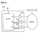
- the electric power steering device 20 is primarily composed of a steering wheel 21, a steering shaft 22, a pinion shaft 23, a rack shaft 24, a torque sensor 30, an electric motor 40, a motor resolver 44, a ball screw mechanism 50, an ECU (Electronic Control Unit) 60 and the like.
- the device 20 detects the steering state on the steering wheel 21 and assists the steering manipulation of the driver by controlling the electric motor 40 to generate an assist force depending on the steering state.
- Opposite ends of the rack shaft 24 are connected to steerable road wheels (usu., front wheels (not shown)) through tie rods and the like, respectively.
- the steering wheel 21 is connected to one end of the steering shaft 22, whose other end is connected by means of a pin 32 to an input shaft 23a of the toque sensor 30 and a torsion bar 31 which are both received in a pinion housing 25.
- the other end 31a of the torsion bar 31 is spline-connected to an output shaft 23b of the pinion shaft 23.
- the input shaft 23a and the output shaft 23b of the pinion shaft 23 are rotatably supported within the pinion housing 25 respectively through bearings 33a and 33b.
- a first resolver 35 constituting the torque sensor 30 is interposed between the input shaft 23a and the pinion housing 25, while a second resolver 37 also constituting the torque sensor 30 is interposed between the output shaft 23b and the pinion housing 25.
- the first and second resolvers 35, 37 are each capable of detecting the steering angle of the steering wheel 21 and are electrically connected to the ECU 60 through respective terminals 39, as typically shown in Figure 5 . The constructions of these resolvers 35, 37 will be described later in detail.
- a rack-and-pinion mechanism is constructed in this manner.
- the steering shaft 22 and the pinion shaft 23 are connected by means of a torsion bar 31 to be rotatable relative to each other through the torsion of the torsion bar 31, and the rotational angle of the steering shaft 22 or the rotational angle (mechanical angle) ⁇ Tm of the steering wheel 21 can be detected based on a first steering angle (electrical angle) ⁇ T1 and a second steering angle (electrical angle) ⁇ T2 which are detected respectively by the first and second resolvers 35, 37. Further, a torsional quantity (corresponding to the steering torque) can be detected as torsional angle based on the angular difference between the first steering angle ⁇ T1 and the second steering angle ⁇ T2, the ratio therebetween or the like.
- the rack shaft 24 is housed within a rack housing 26 and a motor housing 27 to pass therethrough and is formed with a male ball screw 24b at the intermediate portion thereof.
- a motor shaft 43 like a cylindrical sleeve is supported by bearings 29 to be rotatable in coaxial alignment with the rack shaft 24.
- the motor shaft 43 together with an exciting coil 42 and the like, constitutes the electric motor 40, wherein a field system that is generated by the exciting coil 42 wound around a stator 42 acts on permanent magnets 45 arranged on the external surface of the motor shaft 43 serving as a rotor, so that the motor shaft 43 can be rotated.
- the motor shaft 43 has a ball nut 52 fit on its internal surface to be rotatable bodily therewith.
- a female ball screw 52a is formed at the internal surface of the ball nut 52.
- a plurality of balls 54 are interposed between the female ball screw 52a of the ball screw nut 52 and the male ball screw 24b of the rack shaft 24. This constitutes a ball screw mechanism 50 capable of moving the rack shaft 24 in the axial direction thereof upon rotation of the motor shaft 43.
- the ball screw mechanism 50 composed of the both ball screws 24b, 52a and the like is able to convert the rotational torque in the positive-going and negative-going directions of the motor shaft 43 into the reciprocating motion of the rack shaft 24 in the axial direction thereof.
- the reciprocating motion becomes the assist force which reduces the manipulation or steering force to be exerted on the steering wheel 21, through the pinion shaft 23 constituting the rack-and-pinion mechanism together with the rack shaft 24.
- a motor resolver 44 capable of detecting the rotational angle (electrical angle) ⁇ Me of the motor shaft 43 is interposed between the motor shaft 43 of the motor 40 and the motor housing 27.
- the resolver 44 is electrically connected to the ECU 60 through terminals (not shown), as shown in Figure 5 .
- first resolver 35 the second resolver 37 and the motor resolver 44 will be described with reference to Figure 4(A) . Since these resolvers are substantially the same to one another in construction, the first resolver 35 is typically described with respect to those portions common to all the resolvers.
- the first resolver 35 is composed of a first yoke YK1, a second yoke YK2, a third yoke YK3 and a fourth yoke YK4, a first coil CL1, a second coil CL2, a third coil CL3 and a fourth coil CL4, and is of the type having five pole pairs (i.e., a so-called 5X).
- the term "the number of pole pairs" will be described later.
- the first yoke YK1 is formed as an annular cylinder encircled by the internal surface of the pinion housing 25 and is secured to the pinion housing 25.
- the first coil CL1 is wound along the internal surface of the first yoke YK1.
- the second yoke YK2 is formed also as an annular cylinder like the first yoke YK1 and is secured to the circumferential surface of the input shaft 23a of the pinion shaft 23 to face the first yoke YK1.
- the second coil CL2 is wound along the external surface of the second yoke YK2.
- the second yoke YK2 is rotatable bodily with the input shaft 23a.
- the third yoke YK3 is secured to the circumferential surface of the input shaft 23a at a position shifted axially from the second yoke YK2 and thus, is rotatable with the input shaft 23a.
- the third coil CL3 is wound on the third yoke YK3 and is electrically connected to the second coil CL2 of the second yoke YK2 in electrically parallel relation.
- the fourth yoke YK4 is formed as an annular cylinder encircled by the internal surface of the pinion housing 25 and is secured to the pinion housing 25.
- Each of the third and fourth coils CL3, CL4 is composed of two kinds of coils whose phases are shifted 90 degrees from each other, as schematically shown in Figure 5(B) .
- the second resolver 37 is constructed like the first resolver 35 except that the second yoke YK2, the third yoke YK3, the second coil CL2 and the third coil CL3 are provided on the output shaft 23b and that the number of the pole pairs is six (so-called "6X").
- the motor resolver 44 is constructed also like the first resolver 35, but is different from the same in the following respects.
- the first yoke YK1, the fourth yoke YK4, the first coil CL1 and the fourth coil YK4 are provided on the internal surface of the motor housing 27, while the second yoke YK2, the third yoke YK3, the second coil CL2 and the third coil CL3 are provided on the circumferential surface of the motor shaft 43.
- the number of the pole pairs in the motor resolver 44 is seven (so-called "7X").
- the first resolver 35 is composed of the first to fourth coils CL1-CL4 and is of the type so-called "one exciting phase, two output phases" (voltage detection type). Therefore, an exciting signal E1 which is output from an output port P0 of a CPU 61 constituting the ECU 60 is applied to the first coil CL1 and the second coil CL2 constituting a transformer, through a buffer amplifier 63 of the ECU 60 and is further applied to the third coil CL3 serving as one exciting phase. As a result, resolver output signals E2 and E3 depending on a detection angle ⁇ (electrical angle) can be obtained from the fourth coil CL4 including two output phase coils.
- the resolver output signals output from the first resolver 35 are analogue signals composed of a sine-phase signal and a cosine-phase signal, they are converted into digital signals which the CPU 61 can process, by being input into respective A-D (Analogue-to-Digital) converters incorporated in the CPU 61 through buffer amplifiers 64, 65 of the ECU 60.
- A-D Analogue-to-Digital
- the resolver output signals obtained from the first resolver 35 in this manner are converted by the CPU 61 into an electrical angle ⁇ T1 shown in Figure 6
- the resolver output signals obtained from the second resolver 37 are converted by the CPU 61 into another electrical angle ⁇ T2 shown in Figure 6 .
- the electrical angle ⁇ T1 obtained from the first resolver 35 has five (5) peak points per rotation (360 degrees) of the steering wheel 21. This is because the first resolver 35 is of the type having five pole pairs each pair of which is composed of one N-pole and one S-pole in the electrical sense, and because it can output electrical angles corresponding to 1800 degrees (360 x 5) for the 360 degree mechanical angles. In short, the first resolver 35 has a resolution of five (5) times as many as a resolver having a resolution of 360 electrical angles.
- the electrical angle ⁇ T2 obtained from the second resolver 37 has six (6) peak points per rotation (360 degrees) of the steering wheel 21. This is because the second resolver 37 is of the type having six pole pairs each pair of which is composed of one N-pole and one S-pole in the electrical sense, and because it can output electrical angles corresponding to 2160 degrees (360 x 6) for the 360 degree mechanical angles. In short, the second resolver 37 has a resolution of six (6) times as many as a resolver having a resolution of 360 electrical angles.
- the first resolver 35 outputs the electrical angle ⁇ T1 as its resolver signal while the second resolver 37 outputs the electrical angle ⁇ T2 as its resolver signal, but as understood from Figure 6 , they do not take the same value even at any angle of the steering wheel 21. Consequently, over one rotation of the steering wheel 21, a mechanical angle ⁇ Tm of a high resolution can be obtained based on the electrical angle ⁇ T1 of the first resolver 35 and the electrical angle ⁇ T2 of the second resolver 37 through the operation processing executed by the CPU 61.
- the steering torque T can be calculated from the relative rotational difference ⁇ indicating the torsion angle of the torsion bar 31 and the torsional rigidity of the torsion bar 31.
- the CPU 61 of the ECU 60 is able to control the aforementioned motor 40, so that the steering manipulation of the driver can be assisted with the steering force generated by the motor 40.
- motor rotational angle detecting the rotational angle of the motor shaft 43 (hereafter as "motor rotational angle") based on a resolver signal output from the motor resolver 44 can also be explained as follows:
- the CPU 61 composing the ECU 60 is electrically connected to each of the first and second resolvers 35, 37 and the motor resolver 44 through the buffer amplifiers 63, 64, 65. And, the first and second resolvers 35, 37 are able to detect the steering angle (electric angles ⁇ T1, ⁇ T2) of the steering wheel 21, while the motor resolver 44 is able to detect the motor rotational angle (electrical angle ⁇ Me) of the motor 40.
- absolute position detecting processing processing for detecting the absolute angular position of the steering wheel 21 (hereafter referred to as “absolute position detecting processing”) is executed based on the electrical angles ⁇ T1, ⁇ T2, ⁇ Me which are represented respectively by the resolver output signals output from the three resolvers.
- Step S101 processing for acquiring the electrical angles ⁇ T1, ⁇ T2, ⁇ Me of the resolvers 35, 37, 44 is executed at Step S101. More specifically, since the electrical angles ⁇ T1, ⁇ T2 which correspond to the steering angle of the steering wheel 21 are output from the first and second resolvers 35, 37, the resolver signals output from the first and second resolvers 35, 37 are acquired through the buffer amplifies 64, 65 and the A-D converters.
- the electrical angle ⁇ Me which corresponds to the motor rotational angle of the motor 40 is detected from the motor resolver 44, and the resolver signal output from the motor resolver 44 is acquired through the buffer amplifies 64, 65 and the A-D converters.
- Step S103 processing is executed to calculate the mechanical angle ⁇ Tm of the steering wheel 21 from the electrical angles ⁇ T1, ⁇ T2.
- the mechanical angle ⁇ Tm of the steering wheel 21 can be calculated based on the electrical angles ⁇ T1, ⁇ T2 of the two resolvers 35, 37 differing in the number of pole pairs from each other.
- This operation processing is described in detail in Japanese Patent Application No. 2002-196131 filed by the Assignee of the present application, and hence, reference is to be made to that application for details.
- symbol "r” denotes a calculation valve which is the product of the reduction gear ratio of the ball screw mechanism 50 with the number of pole pairs of the motor resolver 44, and as mentioned later, it is the essential requirement that the product is to be a non-integer with a numerical value of the decimal place.
- Step S107 processing is executed to convert the four calculated motor electrical angles ⁇ Me(A) into predetermined angular ranges. That is, in order that each of the calculated motor electrical angles ⁇ Me(A) calculated at Step S105 becomes within an angular range of 0 to 360 degrees, the electrical angles less than 0 degrees are processed to be taken as the absolute values, and the electrical angles larger than 360 degrees are processed under the calculation of " ⁇ Me(A)-INT( ⁇ Me(A) /360) x 360".
- the symbol "INT()" in this calculation stands for a function for converting the quotient within the parenthesis into an integer.
- Step S109 processing is executed to select from the four calculated motor electrical angles ⁇ Me(A) one which is closest in value to an actual motor electrical angle ⁇ Me (hereafter referred to as "real motor electric angle ⁇ Me" to be distinguished from the calculated motor electrical angles ⁇ Me(A)). That is, as mentioned later, of the four calculated motor electrical angles ⁇ Me(A) which have been obtained for the total rotations of the steering wheel 21 at Steps S105 and S109, one of them is the calculated motor electrical angle ⁇ Me(near) that properly represents the absolute position of the steering wheel 21, and therefore, the processing for selecting such one calculated motor electrical angle ⁇ Me(A) is executed at this step S109.
- the processing at this Step 109 may be modified to the processing for selecting one closest to an integer, from all the calculated motor electrical angles ⁇ Me(A) calculated through Steps S105 and S109.
- the processing for selecting one closest to the real motor electrical angle ⁇ Me detected by the motor resolver 44 is executed at this Step S109. This can be done by calculating the differences between the real motor electrical angle ⁇ Me acquired at Step S101 and all the calculated motor electrical angles ⁇ Me(A) and then, by selecting as the calculated motor electrical angle ⁇ Me(near) one corresponding to the smallest difference. In this way of selection, the algorithm for realizing the processing at Step S109 can be simplified compared to the processing for selecting one closest to an integer.
- step S111 processing is performed to judge whether or not, the calculated motor electrical angle ⁇ Me(near) which has been selected through Step S109 is really appropriate. More specifically, the calculated motor electrical angle 6Me(near) has been selected at Step S109 as one which is closest to the real motor electrical angle ⁇ Me detected by the motor resolver 44. However, in the event that the difference between the calculated motor electrical angle ⁇ Me(near) and the real motor electrical angle ⁇ Me exceeds a predetermined threshold value (e.g., 10 degrees), such a high probability can be anticipated that there has arisen an error exceeding a predetermined tolerance.
- a predetermined threshold value e.g. 10 degrees
- Such an error may be due to any one or some of the defects in dimensional accuracy of mechanical components which constitute the pinion shaft 23, the rack shaft 24, the ball screw mechanism 50 or the like, due to the abrasion or the like of the mechanical components, or due to the deterioration in temperature characteristic of semiconductor electronic components such as, for example, operational amplifiers for processing the resolver signals, or the like.
- the occurrence of the abnormality is alerted and a series of the absolute position detecting processing is terminated for the reason of the error.
- the routine proceeds to the next Step S113, wherein processing is executed to calculate an absolute steering angle ⁇ Am.
- Step 113 the parameter A indicative of the calculated motor electrical angle ⁇ Me selected at Step S109 (the index A in this particular embodiment is any of 0, 1,-1 and-2) is substituted into the following equation (4) to execute processing based on the mechanical angle ⁇ Tm of the steering wheel 21 which has been calculated at Step S103.
- the absolute steering angle ⁇ Am of the steering wheel 21 can be detected, so that the series of the absolute position detecting processing is terminated normally.
- ⁇ Am ⁇ Tm + 360 ⁇ A
- the parameter A obtained in this way can be updated or renewed. Accordingly, after the execution of the absolute position detecting processing, the absolute steering angle ⁇ Am can be calculated by the use of the equation noted above.
- updating the parameter A is executed using the following equations (4)' and (4)".
- a judgment is made as to whether or not, the angle which is obtained by subtracting the preceding mechanical angle ⁇ Tm-old from the present mechanical angle ⁇ Tm of the steering wheel 21 exceeds 180 degrees, namely whether or not, the equation (4)' below is satisfied. If the equation (4)' below is satisfied, it is meant that the steering wheel 21 has been rotated more than one rotation in the left turn.
- the parameter A can be updated appropriately, so that after the execution of the aforementioned absolute position detection processing, the absolute steering angle ⁇ Am can be calculated using the equation (4) above.
- the Assignee of the present application has represented a steering angle detected by the torque sensor 30 as symbol ⁇ t (corresponding to the aforementioned mechanical angle ⁇ Tm), an electrical angle of the motor rotational angle as symbol ⁇ m (corresponding to the aforementioned real motor electrical angle ⁇ Me), the absolute position Pt of the steering wheel 21 detected by a torque sensor as an equation (5) below, and the absolute position Pm of the steering wheel 21 detected from the motor rotational angle as an equation (6) below.
- the calculated value (r) is the product of the reduction gear ratio of the ball screw mechanism 50 with the number of pole pairs in the motor resolver 44.
- Pt ⁇ t + 360 ⁇ A
- Pm ⁇ m + 360 ⁇ B / r
- the parameter A is an integer taking one of - 2, -1, 0, 1.
- the parameter B becomes an integer within the range of -126 through 125 in the case that theoretically, there does not arise any error which is caused by the shaking or jolting in the mechanical system connecting the steering wheel 21 with the motor 40 or by the error in the absolute accuracy of the electrical angle of the first and second resolvers 35, 37 constituting the torque sensor 30 or of the motor resolver 44 of the motor 40.
- the time interval Tm1 at which the resolver 44 outputs its detection signal ⁇ m is set as 7 cycles which corresponds to the number of the pole pairs of the motor resolver 44
- the parameter B is the value which is given theoretically as an integer. Actually, however, there are involved some errors due to the shaking in the mechanical system connecting the steering wheel 21 with the motor 40, or due to errors in absolute accuracy of the electrical angles which are detected by the first and second resolvers 35, 37 of the torque sensor 30 and the motor resolver 44 of the motor 40.
- the parameter B includes a value of the decimal place and since four kinds of the B-parameters can be obtained from the equation (8) above in dependence on the values of the parameter A (i.e., -2, -1, 0, 1), a case may occur that in selecting one appropriate value (i.e., true value) as the absolute position of the steering wheel 21, such one appropriate value is confused with other three values (i.e., false values).
- the processing is executed to select the parameter B which of all the B-parameters, is closest to an integer.
- any of the three other values i.e., false values
- the appropriate value i.e., true value
- the calculated value (r) is the product of the reduction gear ratio of the ball screw mechanism 50 with the number of pole pairs in the motor resolver 44.
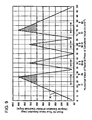
- Figure 9 is a characteristic chart which shows the variation of the room for the true value detection in connection with numerical values of the decimal place of the calculated value (r). The grounds of this characteristic chart will be described later.
- the difference between the true value ⁇ b and the false value ⁇ b closest to the true value ⁇ b is 20 degrees for example.
- the room for the true value detection corresponds to "angular deviation from the motor electrical angle" defined in the patent claims.
- the error due to the shaking of the mechanical system is ⁇ 0.24 degrees and that the detection accuracy of the torque sensor 30 is ⁇ 0.16 degrees
- the error of the mechanical angle ⁇ Tm of the steering wheel 21 which are calculated from the electrical angles ⁇ T1, ⁇ T2 as mentioned previously becomes 0.4 degrees as the sum thereof.
- the error becomes 48.6 degrees which the twice of the 24.3 degrees.
- Step S111 it is judged at Step S111 for the absolute position detecting processing whether or not, the difference between the calculated motor electrical angle ⁇ Me(near) and the real motor electrical angle ⁇ Me exceeds the predetermined threshold value (e.g., 10 degrees), and if it exceeds the predetermined threshold value, the routine under processing is terminated for the reason of abnormality (ERROR).
- the added value of 60 degrees which is made by adding the predetermined threshold value (e.g., 10 degrees) to the error zone boundary (i.e., 50 degrees) can be set as a lower limit value for the angular deviation from the calculated motor electrical angle ⁇ Me(A).
- a room (i.e., 60 degrees) for the true value detection calculated in this manner is also shown as a broken line in Figure 9 .
- the true value can be selected from the plural calculated motor electrical angles ⁇ Me(A) without being confused with other false values at the foregoing Step S109 even in the presence of the error due to the shaking in the mechanical system constituting the electric power steering device 20.
- the room of 60.0 to 90 degrees for the true value detection corresponds to 67% or more and 100% or less of the zigzag line K which represents the variation of the room for the true value detection in relation to the variation in the numerical value of the decimal place of the calculated value (r).
- the numerical value of the decimal place of the calculated value (r) within this zone are within one of ranges "from 0.17 to 0.28", "from 0.39 to 0.42", "from 0.58 to 0.61" and "from 0.72 to 0.83", as extracted from Figure 9 .
- Figure 10(A) shows the characteristic representing the variation of the deviations from the calculated motor electrical angle ⁇ Me(-2) in relation to the numerical values of the decimal place of the calculated value (r).
- the zone e.g., oblique line zone
- 60.0 to 90.0 degrees on the zigzag line K shown in Figure 9 can be applied as it is.
- the reduction gear ratio of the ball screw mechanism 50 is set so that the calculated value (r) which is the product of the reduction gear ratio with the number of pole pairs of the motor resolver 44 becomes a non-integer having a numerical value of the decimal place.
- the calculated value (r) has a zero value as the numerical value less that the decimal point or does not become an integer.
- the absolute position ⁇ Am of the steering wheel 21 can be precisely detected at Step S109 for the absolute position detecting processing executed by the CPU 61 of the ECU 60.
- the motor 40 for assisting the steering manipulation can be controlled by the ECU 60 in dependence on the absolute steering angle ⁇ Am of the steering wheel 21 which is detected in the manner mentioned above.
- the absolute position ⁇ Am of the steering wheel 21 can be precisely detected at Step S109 for the absolute position detecting processing executed by the CPU 61 of the ECU 60. Accordingly, like the case that the reduction gear ratio of the ball screw mechanism 50 is so set, the motor 40 for assisting the steering manipulation can be controlled by the ECU 60 in dependence on the absolute steering angle ⁇ Am of the steering wheel 21.
- the absolute steering angle ⁇ Am of the steering wheel 21 can be detected precisely, so that the ECU 60 is able to control the motor 40 for assisting the steering manipulation, based on the absolute steering angle ⁇ Am of the steering wheel 21 so precisely detected.
- the numerical ranges are for example "0.17 to 0.28", “0.39 to 0.42", "0.58 to 0.61" and "0.72 to 0.83".
- the absolute steering angle ⁇ Am of the steering wheel 21 can be detected precisely, so that the ECU 60 is able to control the motor 40 for assisting the steering manipulation, in dependence on the absolute steering angle ⁇ Am of the steering wheel 21 so precisely detected.
- the step or means for setting the numerical value of the decimal place of the calculated value (r) to one of, e.g., 0.17 to 0.28", “0.39 to 0.42", “0.58 to 0.61” and “0.72 to 0.83” may be replaced by means for setting the reduction gear ratio of the ball screw mechanism 50 by the following equations (9) and (10).
- the steering wheel 21 are rotated two rotations to the left and two rotations to the left and hence, four rotations in total.
- the present invention is not limited to the example as taken in the foregoing embodiment.
- the steering wheel is capable of rotating two rotations or more, the same technological functions and the effects can be obtained, for example, when it is rotated two rotations in total including one to the left and one to the right, when it is rotated six rotations including three to the left and three to the right, or when it Is rotated three rotations including 1.5 to the left and 1.5 to the right.
- the numerical value of the decimal place of the calculated value (r) is within the predetermined range. That is, the numerical value of the decimal place of the calculated value (r) which is obtained by multiplying the reduction gear ration of the reduction gear mechanism with the number of the pole pairs of the third resolver 44 is within the predetermined range.
- the numerical value of of the decimal place of the calculated value (r) is within one of the predetermined ranges.
- This predetermine ranges are numerical ranges of the decimal place which cause those angular deviations corresponding in value to 67% to 100% of the largest one of the angular deviations from the motor electrical angles which deviations are different for the respective rotational range units including at lest one left rotation and one right rotation of said steering wheel.
- the expression "67% to 100% of the largest one of the angular deviations" can be explained by the aforementioned zigzag line K shown in Figure 9 for example and means the oblique-line zones in Figure 9 each of which is within the range of 67% to 100% (60 to 90 degrees) of the largest value (90 degrees) of the zigzag line K.
- the step of and means for setting at least one of the reduction gear ratio of the reduction gear mechanism and the number of pole pairs of the third resolver 44 is so set that the calculated value (r) which is obtained by multiplying the reduction gear ratio with the number of pole pairs of the third resolver 44 represents a non-integer having one of "0.17 to 0.28", “0.39 to 0.42", "0.58 to 0,61” and "0.72 to 0.83" as the numerical value of the decimal place thereof.
- the numerical value of the decimal place of such a calculated value (r) is within one of numerical ranges of the decimal place which cause those angular deviations corresponding in value to 67% to 100% of the largest one of angular deviations from the motor electrical angles ⁇ Me.
- the numerical ranges of the decimal place are represented as "0.17 to 0.28", “0.39 to 0.42", "0.58 to 0.61” and "0.72 to 0.83".
- the absolute position of the steering wheel 21 can be detected precisely, so that the method and apparatus can be obtained for manufacturing the electric power steering device 20 which is capable of controlling the motor 40 for assisting the steering manipulation reliably in dependence on the absolute value of the steering wheel 21 so precisely detected.
- An electric power steering device employs, in addition to a motor resolver of an electric motor for assisting the rotational manipulation of a steering shaft, first and second resolvers which are made different in the number of N-S pole pairs from each other each for detecting the rotational position of the steering shaft.
- the reduction gear ratio of a reduction gear mechanism of a ball screw mechanism driven by the electric motor is set so that a calculated value which is obtained by multiplying the reduction gear ratio with the number of pole pairs of a motor resolver represents a non-integer having a numerical value of the decimal place. Thus, it does not occur that calculated value becomes an integer which does not have any numerical value of the decimal place.
- the mechanical angle of the steering wheel which is calculated based on electrical angles of the first and second resolvers can be made not take the same value within any one-rotational range unit as that within another one-rotational range unit of four rotations in total of the steering wheel including two left rotations and two right rotations. Consequently, it becomes possible to detect the absolute rotational position of the steering wheel precisely, so that the motor for assisting the steering manipulation can reliably be controlled in dependence on the absolute rotational position of the steering wheel so precisely detected.
Description
- The present invention relates to an electric power steering device for employing an electric motor to assisting the steering force applied to road wheels. It further relates a method and apparatus for manufacturing the electric power steering device.
- Heretofore, there have been known electric power steering devices of the type that a steering mechanism connected to a steering shaft is given an assist force generated by an electric motor thereby to reduce the steering force to be applied to a steering wheel. In an electric power steering device of this kind, the steering wheel is rotated more than one full turn to the left and more than one full turn to the right within a limited rotational range. Thus, a neutral position of the steering wheel is assumed to be "the position that the steering wheel takes while the vehicle runs straight ahead", and a steering angle is grasped by detecting as an absolute position the position to which the steering wheel is turned from the neutral position to the left or right.
- And, the steering angle of the steering wheel is usually detected by the use of a rotary angle sensor which is composed of, e.g., a slit disc rotating with the steering shaft and a photo interrupter. For example, taking the configuration like "the steering sensor and the power steering device" disclosed on
pages 2 to 8 and figures 1 to 4 inJapanese unexamined, published patent application No. 2002-145095 - By the way, steering wheels of vehicles are generally of the construction that the angle of steered wheels (usu., front wheels) over the whole range cannot be controlled through the steering within one rotation (360 degrees). For example, as the steering wheel is turned from the center or the neutral position two rotations (720 degrees) in the left direction and two rotations (720 degrees) in the right direction, the steering wheel is capable of varying its steering angle as desired within a predetermined angular range by rotating the steering wheel through 720 degrees toward the plus side or the minus side. For this reason, even where the same construction is taken as "the steering sensor and the power steering device" disclosed in the aforementioned Japanese application, it is impossible to detect the absolute rotational position of the steering wheel in addition to the rotational angle thereof by the use of one rotary angle sensor. Therefore, plural rotary angle sensors have to be combined in detecting the absolute rotational position. However, since in another aspect, the construction using the plural rotary angle sensors directly results in increasing the product cost as well as in heightening the frequency of trouble occurrence, such construction as to increase the number of components is difficult to adopt as a matter of the fact.
- Another electric power steering device has also been known, wherein there are employed a resolver as means for detecting the rotational position of an electric motor which generates the assisting force and another resolver as means for detecting the steering torque generated by a steering wheel. However, it was found through researches of the present inventor that it may occur in dependence on some angular positions of the steering wheel that the latter known electric power steering device cannot precisely distinguish some absolute rotational positions from others precisely or definitely.
-
Document EP 1 026 068 A2 discloses an electric power assistance steering system, in which two sensors, which may be resolvers, are provided, of which one sensor (9) senses the angular position of a motor rotor and the other (10) senses the angular position of a steering shaft connected towheels EP 1 026 068 A2 describes the use of a non-integer gear ratio for a gear box (7) connecting the steering shaft and themotor 6, which serves to provide a "beat" frequency between the outputs of the two sensors is described in more detail. - Document
DE 1997 12 869 A discloses a steering angle sensor system in which two sensors are used in order to enhance redundancy. In particular,DE 1997 12 869 A suggests using sensors having different performances in order to reduce costs. According to this document, it is sufficient to have only one sensor comprising the necessary resolution for detecting an angle, whereas it is sufficient for the other sensor to provide a coarser resolution. Furthermore, it is suggested the use of sensors operating with different measurement methods, for example, using a resolver having pole-pairs (as in the present application) and an optical encoder using CCD technology. - Accordingly, it is a primary object of the present invention to provide an improved electric power steering device capable of precisely detecting the absolute rotational position of a steering wheel even under the condition of error factors being involved therein, so that a motor for assisting the steering manipulation can be controlled based on the absolute rotational position of the steering wheel so precisely detected.
- Another object of the present invention is to provide an improved method and apparatus for manufacturing an electric power steering device which is capable of precisely detecting the absolute rotational position of a steering wheel even under the condition of error factors being involved therein, so that there can be manufactured an electric power steering device which can be operated reliably in dependence on the absolute rotational position of the steering wheel so precisely detected.
- Briefly, according to the present invention, there is provided an electric power steering device, which comprises a steering wheel, a first resolver for detecting a first steering angle indicating the rotational angle of a steering shaft connected to the steering wheel, and a second resolver having pole pairs different in number from those of the first resolver for detecting a second steering angle indicating the rotational angle of the steering shaft. The electric power steering device further comprises an electric motor for assisting the steering operation performed by a steering mechanism connected to the steering shaft, through a reduction gear mechanism, and a third resolver for detecting a motor electrical angle indicating the rotational angle of the electric motor. The electric power steering device is capable of controlling the electric motor based on the absolute rotational position of the steering wheel which is calculated from the first and second steering angles and the motor electrical angle. And, at least one of the reduction gear ratio of the reduction gear mechanism and the number of pole pairs of the third resolver is set so that a calculated value which is obtained by multiplying the reduction gear ratio with the number of the pole pairs represents a non-integer having a numerical value of the decimal place. Herein, the expression "pole pairs" means the gathering of plural pairs each pair of which comprise one N-pole and one S-pole.
- With this construction, since at least one of the reduction gear ratio of the reduction gear mechanism and the number of pole pairs of the third resolver is set so that the calculated value which Is obtained by multiplying the reduction gear ratio with the number of the pole pairs represents a non-integer having a numerical value of the decimal place, it does not occur that the calculated value has zero as its numerical value of the decimal place, in other words, the calculated value becomes an integer. Thus, the steering angle (0 to 360 degrees) within one revolution of the steering wheel which is obtained from the first steering angle of the first resolver and the second steering angle of the second resolver can be made not take the same value within any one-rotational range unit as that within another one-rotational range unit of the plural left and right rotations of the steering wheel. Consequently, it becomes possible to detect the absolute rotational position of the steering wheel precisely, so that the motor for assisting the steering manipulation can reliably be controlled in dependence on the absolute rotational position of the steering wheel so precisely detected.
- In another as aspect of the present invention, a method of manufacturing an electric power steering device is provided, wherein the electric power steering device comprises a steering wheel, a first resolver for detecting a first steering angle indicating the rotational angle of a steering shaft connected to the steering wheel, a second resolver having pole pairs different in number from those of the first resolver for detecting a second steering angle indicating the rotational angle of the steering shaft, an electric motor for assisting the steering operation performed by a steering mechanism connected to the steering shaft, through a reduction gear mechanism, and a third resolver for detecting a motor electrical angle indicating the rotational angle of the electric motor. The electric power steering device is capable of controlling the electric motor based on the absolute rotational position of the steering wheel which is calculated from the first and second steering angles and the motor electrical angle. The method of manufacturing the electric power steering device as constructed above includes the step of setting at least one of the reduction gear ratio of the reduction gear mechanism and the number of pole pairs of the third resolver so that a calculated value which is obtained by multiplying the reduction gear ratio with the number of the pole pairs of the third resolver represents a non-integer which has a numerical value of the decimal place within one of numerical ranges "0.17 to 0.28", "0.39 to 0.42", "0.58 to 0.61" and "0.72 to 0.83".
- In a further aspect of the present invention, an apparatus for manufacturing an electric power steering device is provided, wherein the electric power steering device comprises a steering wheel, a first resolver for detecting a first steering angle indicating the rotational angle of a steering shaft connected to the steering wheel, a second resolver having pole pairs different in number from those of the first resolver for detecting a second steering angle indicating the rotational angle of the steering shaft, an electric motor for assisting the steering operation performed by a steering mechanism connected to the steering shaft, through a reduction gear mechanism, and a third resolver for detecting a motor electrical angle indicating the rotational angle of the electric motor. The electric power steering device is capable of controlling the electric motor based on the absolute rotational position of the steering wheel which is calculated from the first and second steering angles and the motor electrical angle. The apparatus for manufacturing the electric power steering device as constructed above further includes means for setting at least one of the reduction gear ratio of the reduction gear mechanism and the number of pole pairs of the third resolver so that a calculated value which is obtained by multiplying the reduction gear ratio with the number of the pole pairs of the third resolver represents a non-integer which has a numerical value of the decimal place within one of numerical ranges "0.17 to 0.28", "0.39 to 0.42", "0.58 to 0.61" and "0.72 to 0.83".
- The foregoing and other objects and many of the attendant advantages of the present invention may readily be appreciated as the same becomes better understood by reference to the preferred embodiment of the present invention when considered in connection with the accompanying drawings, wherein like reference numerals designate the same or corresponding parts throughout several views, and in which:
-
Figure 1 is an external view partly in section of an electric power steering device of an embodiment according to the present invention; -
Figure 2 is an enlarged view of the part encircled by a one-dot chain line II inFigure 1 ; -
Figure 3 is another enlarged view of the part encircled by a one-dot chain line III inFigure 1 ; -
Figure 4(A) is an explanatory view of resolvers used in the electric power steering device of the embodiment; -
Figure 4(B) is a circuit chart showing the circuit configuration of each of the resolvers; -
Figure 5 is a block diagram showing the configuration in connection between an ECU controlling the electric power steering device of the embodiment and each of the resolvers; -
Figure 6 is a characteristic chart showing resolver signals of first and second resolvers and the mechanical angle of a steering wheel in connection with the rotational angle of the steering wheel; -
Figure 7 is a flow chart showing the flow of absolute position detecting processing executed by the CPU shown inFigure 5 ; -
Figure 8 (A) is a characteristic graph showing the variations of the mechanical angle θTm of a steering wheel and the electrical angle θMe of an electric motor in connection with the rotational amount of the steering wheel in the case of a calculated value being (r)=3.75; -
Figure 8 (B) is another characteristic graph similar toFigure 8 (A) in the case of the calculated value being (r)=3.05; -
Figure 8 (C) is still another characteristic graph similar toFigure 8 (A) in the case of the calculated value being (r)=4.00; -
Figure 9 is a characteristic graph (zigzag line K) showing the variation of a room for true-value detection in connection with a numerical value of the decimal place of the calculated value (r); -
Figure 10(A) is a characteristic graph showing the deviations from calculated motor electrical angles θMe(-2) in connection with the variation in a numerical value of the decimal place of the calculated value (r); -
Figure 10(B) is a similar characteristic graph (zigzag line K) wherein the deviations shown inFigure 10(A) are represented as being turned back each time of reaching the deviation of 180-degrees; -
Figure 11(A) is a characteristic graph showing the deviations from calculated motor electrical angles θMe(-1) in connection with the variation in the numerical value of the decimal place of the calculated value (r); and -
Figure 11(B) is a similar characteristic graph (zigzag line L) wherein the deviations shown inFigure 11(A) are represented as being turned back each time of reaching the deviation of 180-degrees. - Hereafter, an electric power steering device and a method and apparatus for manufacturing the same in the embodiment according to the present invention will be described with reference to the accompanying drawings.
- First of all, the construction of an electric
power steering device 20 in the embodiment according to the present invention will be described with reference toFigures 1 through 6 . As shown inFigures 1 and5 , the electricpower steering device 20 is primarily composed of asteering wheel 21, asteering shaft 22, apinion shaft 23, arack shaft 24, atorque sensor 30, anelectric motor 40, amotor resolver 44, aball screw mechanism 50, an ECU (Electronic Control Unit) 60 and the like. Thedevice 20 detects the steering state on thesteering wheel 21 and assists the steering manipulation of the driver by controlling theelectric motor 40 to generate an assist force depending on the steering state. Opposite ends of therack shaft 24 are connected to steerable road wheels (usu., front wheels (not shown)) through tie rods and the like, respectively. - More specifically, as shown in
Figures 1 and2 , thesteering wheel 21 is connected to one end of thesteering shaft 22, whose other end is connected by means of apin 32 to an input shaft 23a of thetoque sensor 30 and atorsion bar 31 which are both received in apinion housing 25. The other end 31a of thetorsion bar 31 is spline-connected to an output shaft 23b of thepinion shaft 23. - The input shaft 23a and the output shaft 23b of the
pinion shaft 23 are rotatably supported within thepinion housing 25 respectively through bearings 33a and 33b. Afirst resolver 35 constituting thetorque sensor 30 is interposed between the input shaft 23a and thepinion housing 25, while asecond resolver 37 also constituting thetorque sensor 30 is interposed between the output shaft 23b and thepinion housing 25. The first andsecond resolvers steering wheel 21 and are electrically connected to theECU 60 through respective terminals 39, as typically shown inFigure 5 . The constructions of theseresolvers - At an extreme end portion of the output shaft 23b of the
pinion shaft 23, there is formed a pinion gear 23c, to which a rack gear 24a on therack shaft 24 is connected in meshing engagement. Thus, a rack-and-pinion mechanism is constructed in this manner. - With this construction, the steering
shaft 22 and thepinion shaft 23 are connected by means of atorsion bar 31 to be rotatable relative to each other through the torsion of thetorsion bar 31, and the rotational angle of the steeringshaft 22 or the rotational angle (mechanical angle) θTm of thesteering wheel 21 can be detected based on a first steering angle (electrical angle) θT1 and a second steering angle (electrical angle) θT2 which are detected respectively by the first andsecond resolvers - As shown in
Figures 1 and3 , therack shaft 24 is housed within arack housing 26 and amotor housing 27 to pass therethrough and is formed with a male ball screw 24b at the intermediate portion thereof. Around the ball screw 24b, amotor shaft 43 like a cylindrical sleeve is supported bybearings 29 to be rotatable in coaxial alignment with therack shaft 24. Themotor shaft 43, together with anexciting coil 42 and the like, constitutes theelectric motor 40, wherein a field system that is generated by theexciting coil 42 wound around astator 42 acts onpermanent magnets 45 arranged on the external surface of themotor shaft 43 serving as a rotor, so that themotor shaft 43 can be rotated. - The
motor shaft 43 has aball nut 52 fit on its internal surface to be rotatable bodily therewith. A female ball screw 52a is formed at the internal surface of theball nut 52. A plurality ofballs 54 are interposed between the female ball screw 52a of theball screw nut 52 and the male ball screw 24b of therack shaft 24. This constitutes aball screw mechanism 50 capable of moving therack shaft 24 in the axial direction thereof upon rotation of themotor shaft 43. - That is, the
ball screw mechanism 50 composed of the both ball screws 24b, 52a and the like is able to convert the rotational torque in the positive-going and negative-going directions of themotor shaft 43 into the reciprocating motion of therack shaft 24 in the axial direction thereof. Thus, the reciprocating motion becomes the assist force which reduces the manipulation or steering force to be exerted on thesteering wheel 21, through thepinion shaft 23 constituting the rack-and-pinion mechanism together with therack shaft 24. - A
motor resolver 44 capable of detecting the rotational angle (electrical angle) θMe of themotor shaft 43 is interposed between themotor shaft 43 of themotor 40 and themotor housing 27. Theresolver 44 is electrically connected to theECU 60 through terminals (not shown), as shown inFigure 5 . - Now, the constructions of the
first resolver 35, thesecond resolver 37 and themotor resolver 44 will be described with reference toFigure 4(A) . Since these resolvers are substantially the same to one another in construction, thefirst resolver 35 is typically described with respect to those portions common to all the resolvers. - As shown in
Figure 4(A) , thefirst resolver 35 is composed of a first yoke YK1, a second yoke YK2, a third yoke YK3 and a fourth yoke YK4, a first coil CL1, a second coil CL2, a third coil CL3 and a fourth coil CL4, and is of the type having five pole pairs (i.e., a so-called 5X). The term "the number of pole pairs" will be described later. - The first yoke YK1 is formed as an annular cylinder encircled by the internal surface of the
pinion housing 25 and is secured to thepinion housing 25. The first coil CL1 is wound along the internal surface of the first yoke YK1. On the other hand, the second yoke YK2 is formed also as an annular cylinder like the first yoke YK1 and is secured to the circumferential surface of the input shaft 23a of thepinion shaft 23 to face the first yoke YK1. The second coil CL2 is wound along the external surface of the second yoke YK2. Thus, the second yoke YK2 is rotatable bodily with the input shaft 23a. - The third yoke YK3 is secured to the circumferential surface of the input shaft 23a at a position shifted axially from the second yoke YK2 and thus, is rotatable with the input shaft 23a. The third coil CL3 is wound on the third yoke YK3 and is electrically connected to the second coil CL2 of the second yoke YK2 in electrically parallel relation. On the contrary, like the first yoke YK1, the fourth yoke YK4 is formed as an annular cylinder encircled by the internal surface of the
pinion housing 25 and is secured to thepinion housing 25. Each of the third and fourth coils CL3, CL4 is composed of two kinds of coils whose phases are shifted 90 degrees from each other, as schematically shown inFigure 5(B) . - The
second resolver 37 is constructed like thefirst resolver 35 except that the second yoke YK2, the third yoke YK3, the second coil CL2 and the third coil CL3 are provided on the output shaft 23b and that the number of the pole pairs is six (so-called "6X"). - Further, the
motor resolver 44 is constructed also like thefirst resolver 35, but is different from the same in the following respects. In thismotor resolver 44, the first yoke YK1, the fourth yoke YK4, the first coil CL1 and the fourth coil YK4 are provided on the internal surface of themotor housing 27, while the second yoke YK2, the third yoke YK3, the second coil CL2 and the third coil CL3 are provided on the circumferential surface of themotor shaft 43. Further, the number of the pole pairs in themotor resolver 44 is seven (so-called "7X"). - Next, the electrical characteristics of the
first resolver 35, thesecond resolver 37 and themotor resolver 44 will be described with reference toFigure 4(B) . These resolvers are almost the same in electrical characteristic as one another, and therefore, thefirst resolver 35 will be typically described. - As mentioned earlier, the
first resolver 35 is composed of the first to fourth coils CL1-CL4 and is of the type so-called "one exciting phase, two output phases" (voltage detection type). Therefore, an exciting signal E1 which is output from an output port P0 of aCPU 61 constituting theECU 60 is applied to the first coil CL1 and the second coil CL2 constituting a transformer, through a buffer amplifier 63 of theECU 60 and is further applied to the third coil CL3 serving as one exciting phase. As a result, resolver output signals E2 and E3 depending on a detection angle θ (electrical angle) can be obtained from the fourth coil CL4 including two output phase coils. Then, since the resolver output signals output from thefirst resolver 35 are analogue signals composed of a sine-phase signal and a cosine-phase signal, they are converted into digital signals which theCPU 61 can process, by being input into respective A-D (Analogue-to-Digital) converters incorporated in theCPU 61 throughbuffer amplifiers 64, 65 of theECU 60. - In this particular embodiment, the resolver output signals obtained from the
first resolver 35 in this manner are converted by theCPU 61 into an electrical angle θT1 shown inFigure 6 , and in the same manner, the resolver output signals obtained from thesecond resolver 37 are converted by theCPU 61 into another electrical angle θT2 shown inFigure 6 . - Herein, it is noted that the electrical angle θT1 obtained from the
first resolver 35 has five (5) peak points per rotation (360 degrees) of thesteering wheel 21. This is because thefirst resolver 35 is of the type having five pole pairs each pair of which is composed of one N-pole and one S-pole in the electrical sense, and because it can output electrical angles corresponding to 1800 degrees (360 x 5) for the 360 degree mechanical angles. In short, thefirst resolver 35 has a resolution of five (5) times as many as a resolver having a resolution of 360 electrical angles. - Further, it is noted that the electrical angle θT2 obtained from the
second resolver 37 has six (6) peak points per rotation (360 degrees) of thesteering wheel 21. This is because thesecond resolver 37 is of the type having six pole pairs each pair of which is composed of one N-pole and one S-pole in the electrical sense, and because it can output electrical angles corresponding to 2160 degrees (360 x 6) for the 360 degree mechanical angles. In short, thesecond resolver 37 has a resolution of six (6) times as many as a resolver having a resolution of 360 electrical angles. - As mentioned above, the
first resolver 35 outputs the electrical angle θT1 as its resolver signal while thesecond resolver 37 outputs the electrical angle θT2 as its resolver signal, but as understood fromFigure 6 , they do not take the same value even at any angle of thesteering wheel 21. Consequently, over one rotation of thesteering wheel 21, a mechanical angle θTm of a high resolution can be obtained based on the electrical angle θT1 of thefirst resolver 35 and the electrical angle θT2 of thesecond resolver 37 through the operation processing executed by theCPU 61. - Next, description will be made as to the torque detection which is based on the resolver signals output from the first and
second resolvers - When the
steering wheel 21 is manipulated by the driver to rotate the input shaft 23a of thepinion shaft 23 through a rotational angle θ1 with an alternate current voltage E1 being applied to the first coil CL1 shown inFigure 4(B) , a magnetic flux is generated around the first yoke YK1 and the second yoke YK2 in dependence upon the applied voltage E1. - Since at this time, an alternate current voltage depending on the change in the magnetic flux is induced in the second coil CL2, an alternate current voltage is also induced in the third coil CL3 connected to the second coil CL2. The alternate current voltage generated in the third coil CL3 causes an alternate current voltage to be induced in the fourth coil CL4, whereby alternate current voltages E2 and E3 are output. At this time, the alternate current voltages E2 and E3 of two kinds which are different in phase from each other are output from the fourth coil CL4 which is composed of coils of two kinds, and these alternate current voltages E2, E3 respectively satisfy relations expressed by the following equations (1) and (2).


- In the above equations (1) and (2), the symbol "K" represents the voltage transformation ratio.
- Therefore, "θ" can be calculated from the above equations (1) and (2). This angle θ represents the rotational angle θ1 of the input shaft 23b of the
pinion shaft 23. On the other hand, since the output shaft 23b of thepinion shaft 23 which is connected to the input shaft 23a through thetorsion bar 31 is rotated upon rotation of the input shaft 23a, thesecond resolver 37 provided at the side of the output shaft 23b outputs corresponding signals E2 and E3, based on which the rotational angle θ2 can also be calculated using the above equations (1) and (2). - The
torsion bar 31, when given a torsion, brings about the relative rotational difference Δθ (=θ1-θ2) between the input shaft 23a and the output shaft 23b. As a result, the steering torque T can be calculated from the relative rotational difference Δθ indicating the torsion angle of thetorsion bar 31 and the torsional rigidity of thetorsion bar 31. Accordingly, by executing a known assist control for assisting the steering force in dependence on the calculated steering torque T, theCPU 61 of theECU 60 is able to control theaforementioned motor 40, so that the steering manipulation of the driver can be assisted with the steering force generated by themotor 40. - Further, detecting the rotational angle of the motor shaft 43 (hereafter as "motor rotational angle") based on a resolver signal output from the
motor resolver 44 can also be explained as follows: - When the
motor shaft 43 is rotated a certain rotational angle with an alternate current voltage E1 being applied to the first coil CL1 of themotor resolver 44, a magnetic flux is generated around the first yoke YK1 in dependence upon the applied voltage E1, and the generated magnetic flux is conveyed to the second yoke YK2. Since this magnetic flux flows across the second coil YK2 to induce an alternate current voltage, an alternate current voltage is generated also in the third coil CL3 connected to the second coil CL2. The alternate current voltage generated in the third coil CL3 causes an alternate current to be induced in the fourth coil CL4, whereby alternate current voltages E2 and E3 are output. Thus, the motor rotational angle can be calculated by substituting the applied alternate voltage E1 and the output alternate currents E2, E3 into the aforementioned equations (1) and (2). The motor rotational angle detected in this way can be utilized for various controls in the electricpower steering device 20. - Subsequently, the processing for detecting the absolute position of the
steering wheel 21 in the electricpower steering device 20 as constructed above will be described with reference toFigures 7 through Figure 11 . - As described with reference to
Figure 5 , theCPU 61 composing theECU 60 is electrically connected to each of the first andsecond resolvers motor resolver 44 through thebuffer amplifiers 63, 64, 65. And, the first andsecond resolvers steering wheel 21, while themotor resolver 44 is able to detect the motor rotational angle (electrical angle θMe) of themotor 40. Thus, in this particular embodiment, processing for detecting the absolute angular position of the steering wheel 21 (hereafter referred to as "absolute position detecting processing") is executed based on the electrical angles θT1, θT2, θMe which are represented respectively by the resolver output signals output from the three resolvers. It is to be noted that the absolute position detecting processing is executed immediately after an ignition switch is made ON, and in the subsequence to this, a parameter A (A =1, 0, -1, -2) which indicates the range in the rotation of thesteering wheels 21 obtained through the absolute position detecting processing is updated at regular time interval (e.g., each five milliseconds) in response to a timer-based interruption or the like. - As shown in
Figure 7 , in the absolute position detecting processing, after a predetermined initializing processing, processing for acquiring the electrical angles θT1, θT2, θMe of theresolvers steering wheel 21 are output from the first andsecond resolvers second resolvers motor 40 is detected from themotor resolver 44, and the resolver signal output from themotor resolver 44 is acquired through the buffer amplifies 64, 65 and the A-D converters. - At the next Step S103, processing is executed to calculate the mechanical angle θTm of the
steering wheel 21 from the electrical angles θT1, θT2. In this particular embodiment, since the first andsecond resolvers steering wheel 21 can be calculated based on the electrical angles θT1, θT2 of the tworesolvers Japanese Patent Application No. 2002-196131 - At the next step S105, processing is executed to calculate the electrical angle θMe(A) corresponding to each rotational amount (A=1, 0, -1, - 2). For example, with respect to the neutral position of the
steering wheel 21 as the steering center, one rotational range (0<θ≦360 degrees) to the right is set as A=0, and another successive rotational range (360<θ≦ 720 degrees) to the right is set as A=1, while with respect to the neutral position as the steering center, one rotational range (0>θ≧-360 degrees) to the left is set as A=-1 and another successive rotational range (-360<θ≦-720 degrees) to the left is set as A=-2. In the case of the rotational ranges being so set, four calculated motor electrical angles θMe(1), θMe(0), θMe(-1), θMe(-2) which respectively correspond to A=1, 0, -1, -2 are calculated using the following equation (3). That is, at this Step S105, processing is executed to calculate the calculated motor electrical angle θMe(A) for each of the total rotations (in this particular embodiment, for four rotations of the steering wheel 21) of thesteering wheel 21.
- In this equation, symbol "r" denotes a calculation valve which is the product of the reduction gear ratio of the
ball screw mechanism 50 with the number of pole pairs of themotor resolver 44, and as mentioned later, it is the essential requirement that the product is to be a non-integer with a numerical value of the decimal place. In this particular embodiment, since the reduction gear ratio of theball screw mechanism 50 has been set to 8.2 for example, and the number of pole pairs of themotor resolver 44 has been set to 7 for example, the calculated value becomes 57.4 (=8.2 x 7), and the numerical value of the decimal place is 0.4. - Further, at Step S107, processing is executed to convert the four calculated motor electrical angles θMe(A) into predetermined angular ranges. That is, in order that each of the calculated motor electrical angles θMe(A) calculated at Step S105 becomes within an angular range of 0 to 360 degrees, the electrical angles less than 0 degrees are processed to be taken as the absolute values, and the electrical angles larger than 360 degrees are processed under the calculation of "θMe(A)-INT(θMe(A) /360) x 360". The symbol "INT()" in this calculation stands for a function for converting the quotient within the parenthesis into an integer.
- For example, the conversion processing is executed in such a way that where the calculated motor electrical angle θMe(-2) is - 80 degrees, it is converted into +80 degrees (=|-80 degrees|), where the calculated motor electrical angle θMe(1) is 380 degrees, it is converted into 20 degrees (= 380-1
x 360 degrees) and where the calculated motor electrical angle θMe(2) is -400 degrees, it is converted into 40 degrees (= |-400-(-360)|). - At successive Step S109, processing is executed to select from the four calculated motor electrical angles θMe(A) one which is closest in value to an actual motor electrical angle θMe (hereafter referred to as "real motor electric angle θMe" to be distinguished from the calculated motor electrical angles θMe(A)). That is, as mentioned later, of the four calculated motor electrical angles θMe(A) which have been obtained for the total rotations of the
steering wheel 21 at Steps S105 and S109, one of them is the calculated motor electrical angle θMe(near) that properly represents the absolute position of thesteering wheel 21, and therefore, the processing for selecting such one calculated motor electrical angle θMe(A) is executed at this step S109. - The processing at this
Step 109 may be modified to the processing for selecting one closest to an integer, from all the calculated motor electrical angles θMe(A) calculated through Steps S105 and S109. In this particular embodiment, however, the processing for selecting one closest to the real motor electrical angle θMe detected by themotor resolver 44 is executed at this Step S109. This can be done by calculating the differences between the real motor electrical angle θMe acquired at Step S101 and all the calculated motor electrical angles θMe(A) and then, by selecting as the calculated motor electrical angle θMe(near) one corresponding to the smallest difference. In this way of selection, the algorithm for realizing the processing at Step S109 can be simplified compared to the processing for selecting one closest to an integer. - At step S111, processing is performed to judge whether or not, the calculated motor electrical angle θMe(near) which has been selected through Step S109 is really appropriate. More specifically, the calculated motor electrical angle 6Me(near) has been selected at Step S109 as one which is closest to the real motor electrical angle θMe detected by the
motor resolver 44. However, in the event that the difference between the calculated motor electrical angle θMe(near) and the real motor electrical angle θMe exceeds a predetermined threshold value (e.g., 10 degrees), such a high probability can be anticipated that there has arisen an error exceeding a predetermined tolerance. Such an error may be due to any one or some of the defects in dimensional accuracy of mechanical components which constitute thepinion shaft 23, therack shaft 24, theball screw mechanism 50 or the like, due to the abrasion or the like of the mechanical components, or due to the deterioration in temperature characteristic of semiconductor electronic components such as, for example, operational amplifiers for processing the resolver signals, or the like. In such an event, the occurrence of the abnormality is alerted and a series of the absolute position detecting processing is terminated for the reason of the error. (ERROR) - On the contrary, the difference between the calculated motor electrical angle θMe(near) and the actual motor electrical angle θMe is smaller than the predetermined threshold value, it is judged that no error is found in the mechanical components which constitute the
pinion shaft 23, therack shaft 24, theball screw mechanism 50 or the like or the semiconductor electronic components such as, for example, operational amplifiers for processing the resolver signals, or the like. Thus, the routine proceeds to the next Step S113, wherein processing is executed to calculate an absolute steering angle θAm. That is, in this Step 113, the parameter A indicative of the calculated motor electrical angle θMe selected at Step S109 (the index A in this particular embodiment is any of 0, 1,-1 and-2) is substituted into the following equation (4) to execute processing based on the mechanical angle θTm of thesteering wheel 21 which has been calculated at Step S103. As a consequence, the absolute steering angle θAm of thesteering wheel 21 can be detected, so that the series of the absolute position detecting processing is terminated normally.
- By observing the mechanical angle θTm which is obtained from the outputs of the first and
second resolvers - That is, updating the parameter A is executed using the following equations (4)' and (4)". First of all, a judgment is made as to whether or not, the angle which is obtained by subtracting the preceding mechanical angle θTm-old from the present mechanical angle θTm of the
steering wheel 21 exceeds 180 degrees, namely whether or not, the equation (4)' below is satisfied. If the equation (4)' below is satisfied, it is meant that thesteering wheel 21 has been rotated more than one rotation in the left turn. Thus, the parameter A is decremented to renew like A=A-1, and the present mechanical angle θTm is stored as the preceding mechanical angle θTm-old. - If the equation (4)' below is not satisfied, on the contrary, a judgment is made of whether or not, the angle which is obtained by subtracting the preceding mechanical angle θTm-old from the present mechanical angle θTm of the
steering wheel 21 is smaller than 180 degrees, namely whether or not, the equation (4)" below is satisfied. If the equation (4)" below is satisfied, it is meant that thesteering wheel 21 has been rotated more than one rotation in the right turn. Thus, the parameter A is incremented to renew like A=A+1, and the present mechanical angle θTm is stored as the preceding mechanical angle θTm-old. Further, if any of the equations (4)' and (4)" is not satisfied, it is meant that thesteering wheel 21 is being rotated within one rotation in the left or right turn. Thus, it is unnecessary to renew the parameter A and the preceding mechanical angle θTm-old, and the present value of the parameter A and the preceding mechanical angle θTm-old are kept as they are.

- In accordance with this algorithm, the parameter A can be updated appropriately, so that after the execution of the aforementioned absolute position detection processing, the absolute steering angle θAm can be calculated using the equation (4) above.
- Herein, explanation will be made as to the reason why the calculated value (r) of the aforementioned equation (3) used at Step S105 is accompanied by an essential requirement that it should be a non-integer having a numerical value of the decimal place.
- In the
Japanese patent application No. 2002-196131 torque sensor 30 as symbol θt (corresponding to the aforementioned mechanical angle θTm), an electrical angle of the motor rotational angle as symbol θm (corresponding to the aforementioned real motor electrical angle θMe), the absolute position Pt of thesteering wheel 21 detected by a torque sensor as an equation (5) below, and the absolute position Pm of thesteering wheel 21 detected from the motor rotational angle as an equation (6) below. It is noted that the calculated value (r) is the product of the reduction gear ratio of theball screw mechanism 50 with the number of pole pairs in themotor resolver 44.

- In the equation (5), the parameter A is an integer taking one of - 2, -1, 0, 1. In the equation (6), the parameter B becomes an integer within the range of -126 through 125 in the case that theoretically, there does not arise any error which is caused by the shaking or jolting in the mechanical system connecting the
steering wheel 21 with themotor 40 or by the error in the absolute accuracy of the electrical angle of the first andsecond resolvers torque sensor 30 or of themotor resolver 44 of themotor 40. - Since each of the equations (5) and (6) above represents the absolute position of the
steering wheel 21 and since the both equations (5) and (6) are equal to each other, an equation (7) below holds true, from which an equation (8) below is derived.

- In the aforementioned Japanese patent application filed by the Assignee of this application, the calculated value (r) in the equations (5) through (8) above has been represented as being replaced as 57.4. This is because where the
rack shaft 24 is moved S millimeters by one rotation of thesteering wheel 21 and where the lead of theball screw mechanism 50 is L, themotor shaft 43 is rotated through S/L by the S millimeter movement of therack shaft 24, and this motion conversion is set to correspond to 8.2 in the reduction gear ration of theball screw mechanism 50. The reason above is also because where the time interval Tm1 at which theresolver 44 outputs its detection signal θm is set as 7 cycles which corresponds to the number of the pole pairs of themotor resolver 44, the time interval Tm2 at which themotor resolver 44 outputs its detection signal θm for one rotation of the steering shaft 21 (or the pinion shaft 23), in other words, the product which is obtained by multiplying the reduction gear ratio of theball screw mechanism 50 with the number of the poles pairs of themotor resolver 44 becomes 57.4 (= Tml x (S / L)=7 x 8.2). - As mentioned earlier, the parameter B is the value which is given theoretically as an integer. Actually, however, there are involved some errors due to the shaking in the mechanical system connecting the
steering wheel 21 with themotor 40, or due to errors in absolute accuracy of the electrical angles which are detected by the first andsecond resolvers torque sensor 30 and themotor resolver 44 of themotor 40. Therefore, realistically, since the parameter B includes a value of the decimal place and since four kinds of the B-parameters can be obtained from the equation (8) above in dependence on the values of the parameter A (i.e., -2, -1, 0, 1), a case may occur that in selecting one appropriate value (i.e., true value) as the absolute position of thesteering wheel 21, such one appropriate value is confused with other three values (i.e., false values). - That is, in the device described in the aforementioned
Japanese patent application No. 2002-196131 - For example,
Figure 8(A) to 8(C) are characteristic charts each showing the variations of the mechanical angle θTm (Thick line) of thesteering wheel 21 and the real motor electrical angles θMe (Fine line) detected by themotor resolver 44 in relation to the rotational amounts (A =-2, -1, 0, 1) of thesteering wheel 21.Figure 8(A) shows the characteristic in the case of the calculated value being set as r=3.75,Figure 8(B) shows that in the case of the calculated value being set as r=3.05, andFigure 8(C) shows that in the case of the calculated value being set as r=4.00. The calculated value (r) is the product of the reduction gear ratio of theball screw mechanism 50 with the number of pole pairs in themotor resolver 44. - As shown in
Figure 8(A) , in the case that the numerical value of the decimal place is set to 0.75 (e.g., r=3.75), for example, when the value ya which corresponds to the neutral position of thesteering wheel 21 is a true value, three other values αa, βa, δa take respective values which are different 90 degrees from one another as well as from the true value γa. That is,Figure 8(A) demonstrates that even in the presence of errors due to the shaking of the mechanical system or the like, the true value ya has a room of 90 degrees from any of the adjoining values, so that there is little chance to cause the true value γa to be confused with the false values αa, βa, δa. - Also, as shown in
Figure 8(B) , in the case that the numerical value of the decimal place is set to 0.05 (e.g., r=3.05), when the value γb which corresponds to the neutral position of thesteering wheel 21 is a true value, this true value γb has only the difference of about 10 degrees from the false values αb, βb, δb. That is,Figure 8(B) demonstrates that since the true value γb has only a small room of about 10 degrees from the adjoining values, there is some chance for the true value γb to be confused with the false values αb, βb, δb in dependence upon the magnitude of the error due to,e.g., the shaking of the mechanical system. - On the other hand, as shown in
Figure 8(C) , in the case that the numerical value of the decimal place Is set to 0 (zero) (e.g., r= 4.00), when the value γc which corresponds to the neutral position of thesteering wheel 21 is a true value, other false values αc, βc, δc take the same value as the true value γc (there is no room), so that the true value ya cannot be distinguished from other false values αc, βc, δc. That is,Figure 8(C) demonstrates that it is impossible to distinguish the true value γc from other false values αc, βc, δc. - As described above, it can be understood from
Figures 8(A), 8(B), 8(C) that the value (r) which is the product of the reduction gear ratio of theball screw mechanism 50 with the number of pole pairs in themotor resolver 44 substantially has a large influence on selecting the true value from the plural calculated motor electrical angles θMe(A) without confusing with the false values at the aforementioned Step S109. It can also be understood from the figures that in particular, the true value cannot be identified where the value of the calculated value (r) is an integer. This is the ground that it is the essential requirement as mentioned earlier that the calculated value (r) in the equation (3) above with which a calculation processing is executed at Step S105 should be a non-integer having a numerical value of the decimal place. - Next, the influence that such room is given by the errors due to the shaking in the mechanical system constituting the electric
power steering device 20 will be described with reference toFigures 8(A), 8(B), 8(C) andFigure 9. Figure 9 is a characteristic chart which shows the variation of the room for the true value detection in connection with numerical values of the decimal place of the calculated value (r). The grounds of this characteristic chart will be described later. - Herein, the expression "the room for the true value detection" means an index or the like that represents as an absolute value (0≦the smallest deviation < 180 degrees) the difference between the true value and a false value closest to the true value which are selected from among the calculated motor electrical angles θMe(A) of four kinds (A=-2,-1, 0, 1) calculated as mentioned earlier. For example, in the instance shown in
Figure 8(B) , the difference between the true value γb and the false value δb closest to the true value γb is 20 degrees for example. The room for the true value detection corresponds to "angular deviation from the motor electrical angle" defined in the patent claims. - For example, assuming now that in this particular embodiment, the error due to the shaking of the mechanical system is ±0.24 degrees and that the detection accuracy of the
torque sensor 30 is ±0.16 degrees, the error of the mechanical angle θTm of thesteering wheel 21 which are calculated from the electrical angles θT1, θT2 as mentioned previously becomes 0.4 degrees as the sum thereof. - Herein, since the motor electrical angle θMe(A) is calculated by the equation (3) above, the calculated motor electrical angle θMe(0) in the case of A=0, θTm=0 and r=60.67 for example is calculated by replacing θTm with θTm=(0+0.4) including the error 0.4 of the θTm and then, by substituting θTm=(0+0.4) into the equation (3) and becomes ((0+0.4) +360 x 0) x 60.76 = 24.3 degrees). That is, the error 0.4 is multiplied with (r) (in this example, multiplied with 60.76) to be reflected on the calculated motor electrical angles θMe(A). Such error is anticipated to be involved in the true value as well as in the false values adjoining thereto and hence, when calculated under such anticipation, is to be made twice. Thus, the error becomes 48.6 degrees which the twice of the 24.3 degrees.
- Accordingly, as having been described with reference to
Figure 8(A) , even when the true value has a room of 90 degrees from the value adjoining thereto, the error due to the shaking of the mechanical system gives the calculated motor electrical angle θMe(A) an error of almost 50 degrees (≒48.6 degrees), whereby it results that the room is restrained to 40 degrees (=90-50). Where such error zone is represented as shown inFigure 9 , the boundary of the error zone can be specified by drawing a one-dot chain line along the line of the 50-room for the true value detection. - Further, as having been described with reference to
Figure 7 , in this particular embodiment, it is judged at Step S111 for the absolute position detecting processing whether or not, the difference between the calculated motor electrical angle θMe(near) and the real motor electrical angle θMe exceeds the predetermined threshold value (e.g., 10 degrees), and if it exceeds the predetermined threshold value, the routine under processing is terminated for the reason of abnormality (ERROR). In this connection, the added value of 60 degrees which is made by adding the predetermined threshold value (e.g., 10 degrees) to the error zone boundary (i.e., 50 degrees) can be set as a lower limit value for the angular deviation from the calculated motor electrical angle θMe(A). A room (i.e., 60 degrees) for the true value detection calculated in this manner is also shown as a broken line inFigure 9 . - That is, where as shown in
Figure 9 , the numerical value of the decimal place of the calculated value (r) is set to reside in the zone (the oblique line zone inFigure 9 ) within which the room for the true value detection is not smaller than 60.0 degrees and not larger than 90.0 degrees (i.e., 60.0 through 90.0 degrees), the true value can be selected from the plural calculated motor electrical angles θMe(A) without being confused with other false values at the foregoing Step S109 even in the presence of the error due to the shaking in the mechanical system constituting the electricpower steering device 20. - In the concrete, since the room of 60 degrees for the true value detection corresponds to 67 percents (=60/90) of 90 degrees which is the largest value of the zigzag line K shown in
Figure 9 , the room of 60.0 to 90 degrees for the true value detection corresponds to 67% or more and 100% or less of the zigzag line K which represents the variation of the room for the true value detection in relation to the variation in the numerical value of the decimal place of the calculated value (r). And, the numerical value of the decimal place of the calculated value (r) within this zone are within one of ranges "from 0.17 to 0.28", "from 0.39 to 0.42", "from 0.58 to 0.61" and "from 0.72 to 0.83", as extracted fromFigure 9 . Where the calculated value (r) having any of these values has been set, it is possible to select the true value from the plural calculated motor electrical angles θMe(A) without being confused with other false values. It is to be noted that the ranges "from 0.17 to 0.28", "from 0.39 to 0.42", "from 0.58 to 0.61" and "from 0.72 to 0.83" are numerical ranges of the decimal place which cause those angular deviations corresponding in value to 67% to 100% of the largest one of angular deviations from the motor electrical angles which deviations are different for the respective rotational range units including at lest one left rotation and one right rotation of the steering wheel. - Furthermore, where the room for the true value detection is set to 90 degrees which is 100% of the upper limit of the error zone (oblique line zone), it becomes the largest. That is, as understood in
Figure 8(A) , since thesteering wheel 21 is rotated through four rotations as the parameter A varies like A =-2, -1, 0, 1, the 90-degrees obtained by dividing 360 degrees by 4 (=360/4) corresponds to the mid position between the false values βa, δa which are angularly positioned respectively at opposite sides of the true value γa, so that the room for the true value detection becomes the largest. Therefore, the upper limit of the error zone is set to 90 degrees. - Next, the grounds for the characteristic chart (zigzag line K) representing the variation of the room for the true value detection in relation to the numerical values of the decimal place of the calculated value (r) will be described with reference to
Figures 10(A), 10(B) ,11(A), and 11(B) .Figure 10(A) shows the characteristic representing the variation of the deviations from the calculated motor electrical angle θMe(-2) in relation to the numerical values of the decimal place of the calculated value (r). - As having been described with reference to
Figure 8(C) , where the numerical value of the decimal place of the calculated value (r) is set to 0 (zero), the calculated motor electrical angle θMe(A) takes the same value for any of the four-kind rotational amounts (A =-2, -1, 0, 1) of thesteering wheel 21, and therefore, it is unable to distinguish the true value from the false values. That is, inFigure 10(A) , where the numerical value of the decimal place of the calculated value (r) is set to 0 (zero), since the deviation from the broken line for A=-2 becomes zero, each of the solid line for A=-1, the dotted line for A= 0 and the one-dot chain line for A=1 takes 0 (zero) value. - On the contrary, as the numerical value of the decimal place is increased gradually, any of the solid line for A=-1, the dotted line for A= 0 and the one-dot chain line for A=1 increases the deviation from the broken line for A=-2. In this case, the positive inclination amount is enlarged in the sequence or order of the solid line for A=-1, the dotted line for A=0 and the one-dot chain line for A=1. This is because the product of the parameter A with 360 is further multiplied by the calculated value (r), as understood from the equation (3) above. Therefore, taking the broken line for A=-2 as the base, as understood from
Figure 10(A) , the solid line form=-1 varies from 0 to 360 degrees, the dotted line for A=0 varies from 0 to 720 degrees which is twice as much as the solid line for A=-1. And, the one-dot chain line for A=1 varies 0 to 1080 degrees which is three times as much as the solid line for A=-1. - Where the deviations of the calculated motor electrical angle θMe(A) from the base of the broken line for A=-2 are calculated in the respective cases of A=-1, A=0 and A=1 as the numerical value of the decimal place of the calculated value (r) is varied from 0 to 1, it would be understood that a relationship shown in
Figure 10(A) exists among them. And, where the respective deviations so calculated are represented as being turned back each time of reaching 180 degrees, there can be obtained a characteristic chart of a chevron shape as shown inFigure 10(B) . The broken line for A=-2 is omitted inFigure 10(B) . - More specifically, while the solid line for A=-1 increases linearly from 0 to 360 degrees in
Figure 10(A) , it turns back each time of reaching 180 degrees inFigure 10(B) . Thus, the solid line for A=-1 inFigure 10(B) turns back each time the numerical value of the decimal place of the calculated value (r) reaches 0.5, thereby to decrease linearly with a negative inclination and thus, forms a zigzag line (solid line) drawing an isosceles triangle. - And, while the dotted line for A=0 increases linearly from 0 to 720 degrees in
Figure 10(A) , it turns back each time of reaching 180 degrees and 0 degree inFigure 10(B) . Thus, the dotted line for A=0 inFigure 10(B) turns back each time the numerical value of the decimal place of the calculated value (r) reaches 0.25, 0.5 and 0.75, thereby to repeat increase and decrease twice and thus, forms a zigzag line (dotted line) drawing two isosceles triangles. - Further, while the one-dot chain line for A=1 increases linearly from 0 to 1080 degrees in
Figure 10(A) , it turns back each time of reaching 180 degrees and 0 degrees inFigure 10(B) . Thus, the one-dot chain line for A=1 inFigure 10(B) turns back each time the numerical value of the decimal place of the calculated value (r) reaches 0.167, 0.333, 0.5, 0.667 and 0.833 thereby to repeat increase and decrease three times and thus, forms a zigzag line (one-dot chain line) drawing three isosceles triangles. - Further, where the calculated motor electrical angle θMe(-2) in the case of A=-2 is assumed as the true value, each of the zigzag lines represented above shows that as the deviation from the broken line for A=-2 comes close to 0 (zero), the confusion tends to arise between the calculated motor electrical angle θMe(-2) as the true value and the calculated motor electrical angles θMe(-1), θMe(0) and θMe(1) respectively as other false values. Therefore, where the false values each of which is closest to the electrical angle θMe(-2) as the true value at each of the numerical values of the decimal place are selected from the zigzag lines, the zigzag line K (represented by the thick line in
Figure 10(B) can be generated. That is, this zigzag line K is the characteristic (zigzag line K), as described with reference toFigure 9 , which represents the variation in the room for the true value detection in relation to the numerical values of the decimal place of the calculated value (r). - In
Figures 10(A) and 10(B) , the deviations of the calculated motor electrical angles θMe(A) from the broken line for A=-2 taken as the base are calculated in the respective cases of A=-1, A= 0 and A=1 as the numerical value of the decimal place of the calculated value (r) is varied from 0 to 1. However, where the deviations of the calculated motor electrical angles θMe(A) from the solid line for A=-1 taken as the base are calculated in the respective cases of A=-2, A=0 and A=1, they are represented as shown inFigure 11(A) . And, where the deviations represented inFigure 11(A) are represented as being turned back each time of reaching 180 degrees, there can be obtained another characteristic chart of a chevron shape as shown inFigure 11(B) . Then, on the assumption that takes as the true value the calculated motor electrical angle θMe(-1) in the case of A=-1, where the false values each of which is closest to the electrical angle θMe(-1) as the true value at each of numerical values of the decimal place are selected from the zigzag lines, another zigzag line L (represented by the thick one-dot chain line inFigure 11(B) can be generated. The solid line for A=-1 is omitted inFigure 11(B) . - Further, where the deviations of the calculated motor electrical angles θMe(A) from the dotted line for A=0 taken as the base are calculated in the respective cases of A=-2, A=-1 and A= 1, the deviations in the cases of A=-1 and A=1 from the dotted line for A= 0 taken as the base are same, and the deviation in the case of A=-2 is larger than the deviations in the cases of A=-1 and A=1. Therefore, the deviations of the calculated motor electrical angles θMe(A) from the dotted line for A=0 taken as the base can be represented like the case that the broken line for A=-1 is set as the base as shown in
Figures 11(A) and 11(B) . - Further, where the deviations of the calculated motor electrical angles θMe(A) from the one-dot chain line for A=1 taken as the base are calculated in the respective cases of A=-2, A= -1 and A=0, the deviations are shifted in the order of the cases A=0, A=-1 and A=-2. Thus, the deviations from the broke line for A=1 can be represented like the case that the broken line for A=-2 is taken as the base as shown in
Figures 10(A) and 10(B) . - Furthermore, where the characteristic chart in
Figure 10(B) is compared with that inFigure 11(B) , the characteristic of an isosceles triangle which has a peak (the maximum value) at the calculated value (r)= 0.5 in the case of A=-1 shown inFigure 10(B) is the same as the characteristic of an isosceles triangle which has a peak (the maximum value) at the calculated value (r)=0.5 in the cases of A=0 and A= - 2 shown inFigure 11(B) . Similarly, the characteristics of two isosceles triangles which have peaks (the maximum values) at the calculated values (r)=0.25 and (r)=0.75 in the case of A=0 shown inFigure 10(B) are the same as the characteristics of two isosceles triangles which have a peak (the maximum value) at the calculated value (r)= 0.25 in the case of A= 1 and another peak (the maximum value) at the calculated value (r)=0.75 in the case of A=0 shown inFigure 11(B) . - Thus, with respect to the zigzag line L (
Figure 11(B) ) which is obtained by calculating the deviations of the calculated motor electrical angles θMe(A) in the respective cases A=-2, A=0 and A=1 from the broken line in the case of A=-1 and with respect to the zigzag line L (Figure 11(B) ) which is obtained by calculating the deviations of the calculated motor electrical angles θMe(A) in the respective cases A=-2, A=- 1 and A=1 from the dotted line in the case of A=0, the zone (e.g., 60 to 120 degrees) around the largest value (about 120 degrees) comes to be included within the zone (i.e., oblique line zone) of 60.0 to 90 degrees shown by the zigzag line K inFigure 9 . Thus, also in the cases of the broken line for A=-2 and for A=0 being taken as the base, the zone (e.g., oblique line zone) of 60.0 to 90.0 degrees on the zigzag line K shown inFigure 9 can be applied as it is. - As described hereinabove, in the electric
power steering device 20 according to the present embodiment, the reduction gear ratio of theball screw mechanism 50 is set so that the calculated value (r) which is the product of the reduction gear ratio with the number of pole pairs of themotor resolver 44 becomes a non-integer having a numerical value of the decimal place. Thus, it does not take place that the calculated value (r) has a zero value as the numerical value less that the decimal point or does not become an integer. Thus, the mechanical angle θTm of thesteering wheel 21 which can be calculated based on the electrical angle θT1 of thefirst resolver 35 and the electrical angle θT2 of thesecond resolver 37 is made not to take the same value in the rotational range unit (A=-2, -1, 0, 1) of any rotation of the total 4 rotations including two rotations to the left and two rotations to the right, of thesteering wheel 21. As a result, the absolute position θAm of thesteering wheel 21 can be precisely detected at Step S109 for the absolute position detecting processing executed by theCPU 61 of theECU 60. Accordingly, themotor 40 for assisting the steering manipulation can be controlled by theECU 60 in dependence on the absolute steering angle θAm of thesteering wheel 21 which is detected in the manner mentioned above. - In a modified form of the embodiment, the number of pole pairs of the
motor resolver 44 may be set so that the calculated value (r) which is the product of the reduction gear ratio with the number of pole pairs of themotor resolver 44 becomes a non-integer having a numerical value of the decimal place. If so setting is made, the mechanical angle θTm of thesteering wheel 21 which can be calculated based on the electrical angle θT1 of thefirst resolver 35 and the electrical angle θT2 of thesecond resolver 37 is made not to take the same value in the rotational range unit (A =-2, -1, 0, 1) of any rotation of the total 4 rotations including two rotations to the left and two rotations to the right, of thesteering wheel 21. Thus, the absolute position θAm of thesteering wheel 21 can be precisely detected at Step S109 for the absolute position detecting processing executed by theCPU 61 of theECU 60. Accordingly, like the case that the reduction gear ratio of theball screw mechanism 50 is so set, themotor 40 for assisting the steering manipulation can be controlled by theECU 60 in dependence on the absolute steering angle θAm of thesteering wheel 21. - Also, in the electric
power steering device 20 according to the present embodiment, the numerical value of the decimal place of the calculated value (r) is within a predetermined range, and the predetermined range is set to a range of 67% to 100% of the maximum value of the deviations from the calculated motor electrical angle θMe(-2) which are different respectively for the rotational ranges (A =-2, -1, 0, 1) in the four rotations in total including two left rotations and two right rotations of thesteering wheel 21. Thus, even where a detection error arises on the mechanical angle θTm of thesteering wheel 21 due to the defects in dimensional accuracy of the mechanical components which constitute thepinion shaft 23, therack shaft 24, theball screw mechanism 50 or the like, due to the abrasion of the mechanical components or due to the deterioration in temperature characteristic of the electronic components for processing the resolver signals or the like, it can be realized that a rotational range unit and another rotational range unit (in the example shown inFigure 10 for example, between rotational range A=-2 and rotational range A= -1, between rotational range A=-1 and rotational range A=0, and between rotational range A=0 and rotational range A=1) do not take the same value. Accordingly, even where such error occurs, the absolute steering angle θAm of thesteering wheel 21 can be detected precisely, so that theECU 60 is able to control themotor 40 for assisting the steering manipulation, based on the absolute steering angle θAm of thesteering wheel 21 so precisely detected. - Further, in the electric
power steering device 20 and the apparatus and method for manufacturing the electricpower steering device 20, the numerical value of the decimal place of the calculated value (r) is set to be within one of numerical ranges of the decimal place which cause those angular deviations corresponding in value to 67% to 100% of the largest one of angular deviations from the calculated motor electrical angle θMe(-2) which deviations are different for the respective rotational ranges (A =-2, -1, 0, 1) in the four rotations in total including two left rotations and two right rotations of thesteering wheel 21. The numerical ranges are for example "0.17 to 0.28", "0.39 to 0.42", "0.58 to 0.61" and "0.72 to 0.83". Thus, even where a detection error arises on the mechanical angle θTm of thesteering wheel 21 due to the defects in dimensional accuracy of the mechanical components which constitute thepinion shaft 23, therack shaft 24, theball screw mechanism 50 or the like, due to the abrasion of the mechanical components or due to the deterioration in temperature characteristic of the electronic components for processing the resolver signals or the like, it can be realized that a rotational range unit and another rotational range unit (in the example shown inFigure 10 for example, between rotational range A=-2 and rotational range A=-1, between rotational range A=-1 and rotational range A=0 and between rotational range A=0 and rotational range A=1) do not take the same value. Accordingly, even where such error occurs, the absolute steering angle θAm of thesteering wheel 21 can be detected precisely, so that theECU 60 is able to control themotor 40 for assisting the steering manipulation, in dependence on the absolute steering angle θAm of thesteering wheel 21 so precisely detected. - It is to be noted that in the method and apparatus for manufacturing the electric power steering device, the step or means for setting the numerical value of the decimal place of the calculated value (r) to one of, e.g., 0.17 to 0.28", "0.39 to 0.42", "0.58 to 0.61" and "0.72 to 0.83" may be replaced by means for setting the reduction gear ratio of the
ball screw mechanism 50 by the following equations (9) and (10).

- In the foregoing embodiment, description has been made taking the example that the
steering wheel 21 are rotated two rotations to the left and two rotations to the left and hence, four rotations in total. The present invention is not limited to the example as taken in the foregoing embodiment. As long as the steering wheel is capable of rotating two rotations or more, the same technological functions and the effects can be obtained, for example, when it is rotated two rotations in total including one to the left and one to the right, when it is rotated six rotations including three to the left and three to the right, or when it Is rotated three rotations including 1.5 to the left and 1.5 to the right. - Finally, various features and the attendant advantages of the foregoing embodiment will be summarized as follows:
- That is, in the foregoing embodiment, since at least one of the reduction gear ratio of the reduction gear mechanism and the number of pole pairs of the
third resolver 44 is set so that a calculated value (r) which is obtained by multiplying the reduction gear ratio with the number of the pole pairs represents a non-integer having a numerical value of the decimal place, it does not occur that the calculated value (r) has zero as its numerical value of the decimal place, in other words, the calculated value (r) becomes an integer. Thus, the steering angle (0 to 360 degrees) within one revolution of thesteering wheel 21 which is obtained from the first steering angle θT1 of thefirst resolver 35 and the second steering angle θT2 of thesecond resolver 37 can be made not take the same value within any one rotational range unit (A =-2,-1, 0, 1) as that within another rotational range unit of the plural left and right rotations of thesteering wheel 21. Consequently, it becomes possible to detect the absolute rotational position of the steering wheel precisely, so that the motor for assisting the steering manipulation can reliably controlled in dependence on the absolute rotational position of the steering wheel so precisely detected. - Further in the foregoing embodiment, the numerical value of the decimal place of the calculated value (r) is within the predetermined range. That is, the numerical value of the decimal place of the calculated value (r) which is obtained by multiplying the reduction gear ration of the reduction gear mechanism with the number of the pole pairs of the
third resolver 44 is within the predetermined range. Thus, in addition to the advantage that the steering angle (0 to 360 degrees) within one revolution of the steering wheel 12 which is obtained from the first steering angle θT1 of thefirst resolver 35 and the second steering angle θT2 of thesecond resolver 44 does not take the same value within any one rotational range unit (A 2, -1, 0, 1) as that within another rotational range unit of the plural left and right rotations of thesteering wheel 21, non-interference area can be secured between one rotational range unit with another unit next thereto. That is, where an detection error in the steering angle of thesteering wheel 21 arises due to the errors in the dimensional accuracy of the mechanical components which constitute the steering mechanism or due to the abrasion of such mechanical components or due to errors in the temperature characteristic of the electrical components for processing the resolver signals, there can be provided a room for which the numerical value of the decimal place of the calculated value (r) within one rotational range unit of thesteering wheel 21 does not become the same value as that within another range unit next thereto. Thus, even where such error arises, the absolute value of the steering wheel can be detected precisely, so that themotor 40 for assisting the steering manipulation can be controlled reliably in dependence on the absolute value of thesteering wheel 21 so precisely detected. - Also in the foregoing embodiment, the numerical value of of the decimal place of the calculated value (r) is within one of the predetermined ranges. This predetermine ranges are numerical ranges of the decimal place which cause those angular deviations corresponding in value to 67% to 100% of the largest one of the angular deviations from the motor electrical angles which deviations are different for the respective rotational range units including at lest one left rotation and one right rotation of said steering wheel.
- For example, assuming now that with the neutral position of the steering wheel as a center, one rotation range (0<θ≦360 degrees) to the right of the
steering wheel 21 is taken as A=0 and another rotation range (360<θ≦720 degrees) to the right of thesteering wheel 21 is taken as A=1 and that with the neutral position of the steering wheel as the center, one rotation range (0<θ≦-360 degrees) to the left of thesteering wheel 21 is taken as A=-1 and another rotation range (-360<θ≦-720 degrees) to the left of thesteering wheel 21 is taken as A=-2, it was found through experiments and researches by the present inventor that the motor electrical angles within other respective one-rotational ranges A=-1, 0, 1 in relation to the motor electrical angle within one rotational range A=-2 respectively have the angular deviations shown inFigure 10(A) in relation to the numerical value less that the decimal point of the calculated value of the motor electrical angle within one rotational range A=-2. It was also found that where these angular deviations are represented as being turned back each time of reaching a 180-degree electrical angle, there can be obtained the zigzag line K shown inFigure 10(B) (the thick one-dot chain line in the figure). This zigzag line K is generated by selecting the smallest angular deviation from those angular deviations within each of the respective one-rotational ranges A=-1, 0, 1 for each of the numerical values (0 to 1) of the decimal place. - Herein, the expression "the angular deviations of the motor electrical angles which are different for respective rotational range units including at least one left rotation and one right rotation of the steering wheel" means those represented by the zigzag line K which, as shown in
Figure 10(b) , shows the deviations from the motor electrical angles within the one rotational range unit A=-2 in relation to the variation in the numerical value of the decimal place of the calculated value (r). Further, the expression "67% to 100% of the largest one of the angular deviations" can be explained by the aforementioned zigzag line K shown inFigure 9 for example and means the oblique-line zones inFigure 9 each of which is within the range of 67% to 100% (60 to 90 degrees) of the largest value (90 degrees) of the zigzag line K. - With the arrangement made above, even where an detection error in the steering angle of the
steering wheel 21 arises due to the errors in the dimensional accuracy of the mechanical components which constitute the steering mechanism, due to the abrasion of such mechanical components, or due to the errors in the temperature characteristics of the electrical components for processing the resolver signals, it can be realized that the calculated values of the motor electrical angles do not become the same values between two one-rotational range units (in the instance ofFigure 10(A) for example, between one rotational range A=-2 and one rotational range A=-1, between one rotational range A=-1 and one rotational range A=0, and between one rotational range A=0 and one rotational range A=1) which adjoin to each other due to such errors. Accordingly, even where such an error arises, the absolute position of thesteering wheel 21 can be detected precisely, so that themotor 40 for assisting the steering manipulation can be controlled reliably in dependence on the absolute value of thesteering wheel 21 so precisely detected. - Furthermore, in the embodiment implementing the method of manufacturing the electric power steering device and in the embodiment realizing the apparatus for manufacturing the same, the step of and means for setting at least one of the reduction gear ratio of the reduction gear mechanism and the number of pole pairs of the
third resolver 44 is so set that the calculated value (r) which is obtained by multiplying the reduction gear ratio with the number of pole pairs of thethird resolver 44 represents a non-integer having one of "0.17 to 0.28", "0.39 to 0.42", "0.58 to 0,61" and "0.72 to 0.83" as the numerical value of the decimal place thereof. That is, the numerical value of the decimal place of such a calculated value (r) is within one of numerical ranges of the decimal place which cause those angular deviations corresponding in value to 67% to 100% of the largest one of angular deviations from the motor electrical angles θMe. The angular deviations are different for the respective rotational range units (A =-2, -1, 0, 1) including at lest one left rotation and one right rotation of thesteering wheel 21. In the concrete, the numerical ranges of the decimal place are represented as "0.17 to 0.28", "0.39 to 0.42", "0.58 to 0.61" and "0.72 to 0.83". The reason why these numerical ranges are provided is that, assuming that with respect to the neutral position of thesteering wheel 21 as a center, one rotation range (0<θ≦360 degrees) to the right of the steering wheel is taken as A=0 and another rotation range (360<θ≦720 degrees) to the right of the steering wheel is taken as A=1 and that with respect to the neutral position of the steering wheel as the center, one rotation range (0<θ≦-360 degrees) to the left of the steering wheel is taken as A=-1, and another rotation range (-360<θ≦-720 degrees) to the left of the steering wheel is taken as A=-2, the zigzag line K shown inFigure 9 can be obtained by choosing the smallest angular deviation (A=-2 as shown inFigure 10(A) ) as the base from those deviations within the respective one-rotational ranges A=-2,-1, 0, 1. - Thus, even where an detection error in the steering angle of the
steering wheel 21 arises due to the errors in the dimensional accuracy of the mechanical components which constitute the steering mechanism, due to the abrasion of such mechanical components, or due to errors in the temperature characteristics of the electrical components for processing the resolver signals, it can be realized that the calculated values of the motor electrical angles θMe do not become the same values between two one-rotational ranges (inFigure 10(A) for example, between one rotational range A=-2 and one rotational range A=-1, between one rotational range A=-1 and one rotational range A=0, and between one rotational range A=0 and one rotational range A=1) which adjoin to each other due to the error. Accordingly, even where such an error arises, the absolute position of thesteering wheel 21 can be detected precisely, so that the method and apparatus can be obtained for manufacturing the electricpower steering device 20 which is capable of controlling themotor 40 for assisting the steering manipulation reliably in dependence on the absolute value of thesteering wheel 21 so precisely detected. - An electric power steering device according to the embodiment disclosed herein employs, in addition to a motor resolver of an electric motor for assisting the rotational manipulation of a steering shaft, first and second resolvers which are made different in the number of N-S pole pairs from each other each for detecting the rotational position of the steering shaft. The reduction gear ratio of a reduction gear mechanism of a ball screw mechanism driven by the electric motor is set so that a calculated value which is obtained by multiplying the reduction gear ratio with the number of pole pairs of a motor resolver represents a non-integer having a numerical value of the decimal place. Thus, it does not occur that calculated value becomes an integer which does not have any numerical value of the decimal place. As a result, it can be realized that the mechanical angle of the steering wheel which is calculated based on electrical angles of the first and second resolvers can be made not take the same value within any one-rotational range unit as that within another one-rotational range unit of four rotations in total of the steering wheel including two left rotations and two right rotations. Consequently, it becomes possible to detect the absolute rotational position of the steering wheel precisely, so that the motor for assisting the steering manipulation can reliably be controlled in dependence on the absolute rotational position of the steering wheel so precisely detected.
Claims (3)
- An electric power steering device having
a steering wheel (21);
a first resolver (35) for detecting a first steering angle (θT1) indicating the rotational angle of a steering shaft (22) connected to said steering wheel;
a second resolver (37) having pole pairs different in number from those of said first resolver for detecting a second steering angle (θT2) indicating the rotational angle of said steering shaft;
an electric motor (40) for assisting the steering operation performed by a steering mechanism connected to said steering shaft, through a reduction gear mechanism (50); and
a third resolver (44) for detecting a motor electrical angle (θMe) indicating the rotational angle of said electric motor, said electric power steering device being capable of controlling said electric motor based on the rotational position of said steering wheel which is calculated based on said first and second steering angles and said motor electric angle, wherein:at least one of the reduction gear ratio of said reduction gear mechanism and the number of pole pairs of said third resolver is set so that a calculated value which is obtained by multiplying said reduction gear ratio with said number of said pole pairs represents a non-integer having a numerical value of the decimal place within one of numerical ranges "0.17 to 0.28", "0.39 to 0.42", "0.58 to 0.61" and "0.72 to 0.83". - The device as set forth in Claim 1, wherein said numerical ranges of the decimal place cause those angular deviations corresponding in value to 67% to 100% of the largest one of angular deviations from said motor electrical angles which deviations are different for the respective rotational range units including at lest one left rotation and one right rotation of said steering wheel.
- A method of manufacturing an electric power steering device, comprising the steps of
manufacturing an electric power steering device having a steering wheel (21); a first resolver (35) for detecting a first steering angle (θT1) indicating the rotational angle of a steering shaft connected to said steering wheel (22); a second resolver (37) having pole pairs different in number from those of said first resolver for detecting a second steering angle (θT2) indicating the rotational angle of said steering shaft; an electric motor (40) for assisting the steering operation performed by a steering mechanism connected to said steering shaft, through a reduction gear mechanism (50); and a third resolver (44) for detecting a motor electrical angle (θMe) indicating the rotational angle of said electric motor; said electric power steering device being capable of controlling said electric motor based on the absolute rotational position of said steering wheel which is calculated from said first and second steering angles and said motor electrical angle,
said method including the step of setting at least one of said reduction gear ratio of said reduction gear mechanism and the number of pole pairs of said third resolver so that a calculated value which is obtained by multiplying said reduction gear ratio with said number of pole pairs of said third resolver represents a non-integer which has a numerical value of the decimal place within one of numerical ranges "0.17 to 0.28", "0.39 to 0.42", "0.58 to 0.61" and "0.72 to 0.83".
Applications Claiming Priority (2)
| Application Number | Priority Date | Filing Date | Title |
|---|---|---|---|
| JP2002309252 | 2002-10-24 | ||
| JP2002309252 | 2002-10-24 |
Publications (2)
| Publication Number | Publication Date |
|---|---|
| EP1413499A1 EP1413499A1 (en) | 2004-04-28 |
| EP1413499B1 true EP1413499B1 (en) | 2008-02-13 |
Family
ID=32064353
Family Applications (1)
| Application Number | Title | Priority Date | Filing Date |
|---|---|---|---|
| EP03024469A Expired - Fee Related EP1413499B1 (en) | 2002-10-24 | 2003-10-23 | Steering angle sensor arrangement for an electric power steering device |
Country Status (3)
| Country | Link |
|---|---|
| US (1) | US6994181B2 (en) |
| EP (1) | EP1413499B1 (en) |
| DE (1) | DE60319045T2 (en) |
Families Citing this family (18)
| Publication number | Priority date | Publication date | Assignee | Title |
|---|---|---|---|---|
| JP4042049B2 (en) * | 2003-04-16 | 2008-02-06 | 株式会社ジェイテクト | Steering angle detection device for electric power steering device |
| JP4604551B2 (en) | 2003-09-24 | 2011-01-05 | 株式会社ジェイテクト | Resolver signal arithmetic processing method and arithmetic processing apparatus |
| ES2277664T3 (en) * | 2004-03-10 | 2007-07-16 | Umbra Cuscinetti S.P.A. | STEERING UNIT FOR AN ELECTRIC VEHICLE. |
| DE102004046946B4 (en) * | 2004-09-28 | 2013-10-02 | Trw Automotive Gmbh | Method for mounting a steering angle and steering torque sensor and steering gear with a steering angle and steering torque sensor |
| US7325646B2 (en) * | 2005-07-15 | 2008-02-05 | Jtekt Corporation | Electric power steering apparatus |
| RU2278797C1 (en) * | 2005-08-19 | 2006-06-27 | Открытое акционерное общество "Калужский завод электронных изделий" | Electromechanical steering booster and steering booster electric motor |
| CN101534630A (en) * | 2006-05-24 | 2009-09-16 | Tt电子技术有限公司 | Multiturn rotational sensor |
| EP1879087A3 (en) * | 2006-07-10 | 2010-08-18 | Brose Schliesssysteme GmbH & Co. KG | Position detection assembly for a motor-driven adjustable functional element in a motor vehicle |
| DE102007027041B4 (en) * | 2006-07-13 | 2015-01-15 | Ford Global Technologies, Llc | Method for determining a torque on a steering line |
| DE602007002453D1 (en) * | 2006-08-21 | 2009-10-29 | Jtekt Corp | steering device |
| EP1990256B1 (en) * | 2007-05-08 | 2011-06-15 | Jtekt Corporation | Electric power steering device |
| JP4863953B2 (en) * | 2007-08-30 | 2012-01-25 | 日立オートモティブシステムズ株式会社 | Physical quantity conversion sensor and motor control system using the same |
| KR101450320B1 (en) * | 2010-04-20 | 2014-10-21 | 주식회사 만도 | Rack Assist Type Electric Power Steering Apparatus having Ball Reducer |
| KR101450322B1 (en) * | 2011-01-31 | 2014-10-21 | 주식회사 만도 | Rack Assist Type Electric Power Steering Apparatus having Ball Reducer |
| WO2013175729A1 (en) | 2012-05-22 | 2013-11-28 | 日本精工株式会社 | Vehicle steering angle detection device and electric power steering device |
| EP3122615A4 (en) * | 2014-03-28 | 2017-06-28 | Allied Motion Stockholm AB | Method for deriving an absolute multiturn rotational angle of a rotating shaft, and a device therefore |
| FR3039491B1 (en) * | 2015-07-31 | 2017-08-11 | Jtekt Europe Sas | ASSISTED STEERING DEVICE WITH SEALED PROTECTION COVER |
| CN106926894A (en) * | 2015-12-31 | 2017-07-07 | 罗伯特·博世有限公司 | Steering wheel rotation information determining device and steering wheel rotation information determine method |
Citations (3)
| Publication number | Priority date | Publication date | Assignee | Title |
|---|---|---|---|---|
| EP1020344A1 (en) * | 1999-01-15 | 2000-07-19 | TRW LucasVarity Electric Steering Limited | Electrical power assisted steering assemblies |
| DE19941101A1 (en) * | 1999-08-30 | 2001-03-01 | Delphi Tech Inc | Sensor arrangement for steering wheel angle in motor vehicle has three sensor units for determining rotary position of steering wheel, evaluation circuit that evaluates signals from all units |
| EP1291264A2 (en) * | 2001-09-05 | 2003-03-12 | Toyoda Koki Kabushiki Kaisha | Apparatus and method for detecting absolute position |
Family Cites Families (21)
| Publication number | Priority date | Publication date | Assignee | Title |
|---|---|---|---|---|
| JPS59226806A (en) | 1983-06-08 | 1984-12-20 | Fanuc Ltd | Absolute position detector |
| JPH037673A (en) * | 1989-05-24 | 1991-01-14 | Mitsubishi Electric Corp | Motor-driven front & rear wheel steering device |
| US5202614A (en) * | 1989-09-25 | 1993-04-13 | Silicon Systems, Inc. | Self-commutating, back-emf sensing, brushless dc motor controller |
| US5072166A (en) * | 1990-06-18 | 1991-12-10 | The Texas A&M University System | Position sensor elimination technique for the switched reluctance motor drive |
| US5028852A (en) * | 1990-06-21 | 1991-07-02 | Seagate Technology, Inc. | Position detection for a brushless DC motor without hall effect devices using a time differential method |
| US5254914A (en) * | 1990-06-29 | 1993-10-19 | Seagate Technology, Inc. | Position detection for a brushless DC motor without Hall effect devices using a mutual inductance detection method |
| JPH072135A (en) | 1993-06-17 | 1995-01-06 | Toyota Motor Corp | Motor-operated power steering device |
| JP3095961B2 (en) * | 1994-10-04 | 2000-10-10 | 本田技研工業株式会社 | Steering reaction force control device for vehicle steering system |
| EP0710600B1 (en) * | 1994-11-04 | 2001-10-24 | Trw Inc. | Method and apparatus for controlling an electric motor |
| DE19506938A1 (en) * | 1995-02-28 | 1996-08-29 | Bosch Gmbh Robert | Method and device for measuring the angle of a rotatable body |
| JP3218950B2 (en) * | 1995-12-11 | 2001-10-15 | トヨタ自動車株式会社 | Vehicle steering control device |
| US5786754A (en) * | 1995-12-13 | 1998-07-28 | Trw Inc. | Method and apparatus for electronically cancelling a vehicle direction signal in an electric assist steering system |
| US5880367A (en) * | 1996-07-11 | 1999-03-09 | First Inertia Switch Limited | Vehicle steering sensor device |
| DE19712869A1 (en) * | 1997-03-27 | 1998-10-01 | Itt Mfg Enterprises Inc | Steering angle sensor system with increased redundancy |
| GB9716658D0 (en) * | 1997-08-07 | 1997-10-15 | Lucas Ind Plc | Improvements relating to motors |
| GB9902438D0 (en) * | 1999-02-05 | 1999-03-24 | Trw Lucas Varity Electric | Improvements relating to electric power assisted steering assemblies |
| US6519549B1 (en) * | 2000-07-31 | 2003-02-11 | Delphi Technologies, Inc. | Method and device for determining absolute angular position of a rotating body |
| DE10048911C1 (en) * | 2000-10-02 | 2002-04-25 | Ruf Electronics Gmbh | Method and device for determining the absolute position in position and angle encoders |
| US6469499B2 (en) * | 2001-02-06 | 2002-10-22 | Delphi Technologies, Inc. | Apparatus and method for low power position sensing systems |
| JP2003329524A (en) * | 2002-05-13 | 2003-11-19 | Koyo Seiko Co Ltd | Torque detector |
| JP4042049B2 (en) * | 2003-04-16 | 2008-02-06 | 株式会社ジェイテクト | Steering angle detection device for electric power steering device |
-
2003
- 2003-10-23 EP EP03024469A patent/EP1413499B1/en not_active Expired - Fee Related
- 2003-10-23 DE DE60319045T patent/DE60319045T2/en not_active Expired - Lifetime
- 2003-10-24 US US10/691,543 patent/US6994181B2/en not_active Expired - Lifetime
Patent Citations (3)
| Publication number | Priority date | Publication date | Assignee | Title |
|---|---|---|---|---|
| EP1020344A1 (en) * | 1999-01-15 | 2000-07-19 | TRW LucasVarity Electric Steering Limited | Electrical power assisted steering assemblies |
| DE19941101A1 (en) * | 1999-08-30 | 2001-03-01 | Delphi Tech Inc | Sensor arrangement for steering wheel angle in motor vehicle has three sensor units for determining rotary position of steering wheel, evaluation circuit that evaluates signals from all units |
| EP1291264A2 (en) * | 2001-09-05 | 2003-03-12 | Toyoda Koki Kabushiki Kaisha | Apparatus and method for detecting absolute position |
Also Published As
| Publication number | Publication date |
|---|---|
| DE60319045T2 (en) | 2009-02-05 |
| EP1413499A1 (en) | 2004-04-28 |
| DE60319045D1 (en) | 2008-03-27 |
| US6994181B2 (en) | 2006-02-07 |
| US20050016789A1 (en) | 2005-01-27 |
Similar Documents
| Publication | Publication Date | Title |
|---|---|---|
| EP1413499B1 (en) | Steering angle sensor arrangement for an electric power steering device | |
| US7325646B2 (en) | Electric power steering apparatus | |
| EP1462340B1 (en) | Electrically driven steering apparatus | |
| EP2159548A2 (en) | Abnormality detection unit for resolver and electric power steering apparatus | |
| EP1468900B1 (en) | Vehicle steering apparatus | |
| US20030046012A1 (en) | Apparatus and method for detecting absolute position | |
| EP2078661A1 (en) | Steering System for vehicle | |
| US20050230179A1 (en) | Vehicle steering apparatus | |
| EP1516799B1 (en) | Electric power steering apparatus and angle compensating method therefor | |
| JP3969220B2 (en) | Absolute position detection device and absolute position detection method for electric power steering device | |
| EP1197725A2 (en) | Rotational angle detecting apparatus, torque sensor and steering apparatus | |
| EP1910155B1 (en) | Steering angle sensing apparatus and method thereof | |
| EP1519174B1 (en) | Resolver signal processing method and processing apparatus | |
| EP1462341B1 (en) | Setting method for control parameter, setting device for control parameter, and electric power steering device | |
| EP1462786B1 (en) | Torque sensor and electric steering device using the same | |
| EP1586864B1 (en) | Rotation angle detecting apparatus and electric power steering apparatus | |
| JP5311102B2 (en) | Vehicle steering system | |
| US6935194B2 (en) | Dual resolver device | |
| JP4020013B2 (en) | Vehicle steering system | |
| JP3875202B2 (en) | Electric power steering apparatus, manufacturing method and manufacturing apparatus thereof | |
| JP4438386B2 (en) | Torque detection device | |
| JP2005098781A (en) | Failure detection method and device of torque sensor | |
| JP7192822B2 (en) | Steering angle estimation device, steering device, and steering angle estimation method | |
| JP2007155641A (en) | Resolver device and torque sensor using the same |
Legal Events
| Date | Code | Title | Description |
|---|---|---|---|
| PUAI | Public reference made under article 153(3) epc to a published international application that has entered the european phase |
Free format text: ORIGINAL CODE: 0009012 |
|
| AK | Designated contracting states |
Kind code of ref document: A1 Designated state(s): AT BE BG CH CY CZ DE DK EE ES FI FR GB GR HU IE IT LI LU MC NL PT RO SE SI SK TR |
|
| AX | Request for extension of the european patent |
Extension state: AL LT LV MK |
|
| 17P | Request for examination filed |
Effective date: 20040914 |
|
| AKX | Designation fees paid |
Designated state(s): DE FR GB |
|
| RAP1 | Party data changed (applicant data changed or rights of an application transferred) |
Owner name: JTEKT CORPORATION |
|
| RIN1 | Information on inventor provided before grant (corrected) |
Inventor name: ASADA, ATSUHISA |
|
| GRAP | Despatch of communication of intention to grant a patent |
Free format text: ORIGINAL CODE: EPIDOSNIGR1 |
|
| GRAS | Grant fee paid |
Free format text: ORIGINAL CODE: EPIDOSNIGR3 |
|
| GRAA | (expected) grant |
Free format text: ORIGINAL CODE: 0009210 |
|
| AK | Designated contracting states |
Kind code of ref document: B1 Designated state(s): DE FR GB |
|
| REG | Reference to a national code |
Ref country code: GB Ref legal event code: FG4D |
|
| REF | Corresponds to: |
Ref document number: 60319045 Country of ref document: DE Date of ref document: 20080327 Kind code of ref document: P |
|
| ET | Fr: translation filed | ||
| PLBE | No opposition filed within time limit |
Free format text: ORIGINAL CODE: 0009261 |
|
| STAA | Information on the status of an ep patent application or granted ep patent |
Free format text: STATUS: NO OPPOSITION FILED WITHIN TIME LIMIT |
|
| 26N | No opposition filed |
Effective date: 20081114 |
|
| PGFP | Annual fee paid to national office [announced via postgrant information from national office to epo] |
Ref country code: GB Payment date: 20081022 Year of fee payment: 6 |
|
| PG25 | Lapsed in a contracting state [announced via postgrant information from national office to epo] |
Ref country code: GB Free format text: LAPSE BECAUSE OF NON-PAYMENT OF DUE FEES Effective date: 20091023 |
|
| REG | Reference to a national code |
Ref country code: FR Ref legal event code: PLFP Year of fee payment: 14 |
|
| REG | Reference to a national code |
Ref country code: FR Ref legal event code: PLFP Year of fee payment: 15 |
|
| REG | Reference to a national code |
Ref country code: FR Ref legal event code: PLFP Year of fee payment: 16 |
|
| PGFP | Annual fee paid to national office [announced via postgrant information from national office to epo] |
Ref country code: FR Payment date: 20200914 Year of fee payment: 18 |
|
| PGFP | Annual fee paid to national office [announced via postgrant information from national office to epo] |
Ref country code: DE Payment date: 20201013 Year of fee payment: 18 |
|
| REG | Reference to a national code |
Ref country code: DE Ref legal event code: R119 Ref document number: 60319045 Country of ref document: DE |
|
| PG25 | Lapsed in a contracting state [announced via postgrant information from national office to epo] |
Ref country code: DE Free format text: LAPSE BECAUSE OF NON-PAYMENT OF DUE FEES Effective date: 20220503 |
|
| PG25 | Lapsed in a contracting state [announced via postgrant information from national office to epo] |
Ref country code: FR Free format text: LAPSE BECAUSE OF NON-PAYMENT OF DUE FEES Effective date: 20211031 |