EP1412732B1 - Halbleiterbauelement als kapazitiver feuchtesensor, sowie ein verfahren zur herstellung des halbleiterbauelements - Google Patents
Halbleiterbauelement als kapazitiver feuchtesensor, sowie ein verfahren zur herstellung des halbleiterbauelements Download PDFInfo
- Publication number
- EP1412732B1 EP1412732B1 EP02754323A EP02754323A EP1412732B1 EP 1412732 B1 EP1412732 B1 EP 1412732B1 EP 02754323 A EP02754323 A EP 02754323A EP 02754323 A EP02754323 A EP 02754323A EP 1412732 B1 EP1412732 B1 EP 1412732B1
- Authority
- EP
- European Patent Office
- Prior art keywords
- layer
- electrode
- capacitive sensor
- sensor according
- medium
- Prior art date
- Legal status (The legal status is an assumption and is not a legal conclusion. Google has not performed a legal analysis and makes no representation as to the accuracy of the status listed.)
- Expired - Lifetime
Links
- 239000004065 semiconductor Substances 0.000 title claims abstract description 20
- 238000004519 manufacturing process Methods 0.000 title description 4
- 239000011148 porous material Substances 0.000 claims abstract description 15
- 229910052710 silicon Inorganic materials 0.000 claims abstract description 12
- 239000010703 silicon Substances 0.000 claims abstract description 12
- 239000000758 substrate Substances 0.000 claims abstract description 10
- 238000005530 etching Methods 0.000 claims description 21
- KRHYYFGTRYWZRS-UHFFFAOYSA-N Fluorane Chemical compound F KRHYYFGTRYWZRS-UHFFFAOYSA-N 0.000 claims description 10
- 238000000034 method Methods 0.000 claims description 9
- 239000000463 material Substances 0.000 claims description 3
- 239000000654 additive Substances 0.000 claims 5
- 230000000996 additive effect Effects 0.000 claims 5
- LFQSCWFLJHTTHZ-UHFFFAOYSA-N Ethanol Chemical compound CCO LFQSCWFLJHTTHZ-UHFFFAOYSA-N 0.000 claims 3
- 230000015572 biosynthetic process Effects 0.000 claims 1
- 238000001035 drying Methods 0.000 claims 1
- 230000005684 electric field Effects 0.000 claims 1
- -1 for example ethanol Chemical compound 0.000 claims 1
- 239000007788 liquid Substances 0.000 claims 1
- 238000009736 wetting Methods 0.000 claims 1
- 239000010410 layer Substances 0.000 description 53
- 239000003990 capacitor Substances 0.000 description 11
- XUIMIQQOPSSXEZ-UHFFFAOYSA-N Silicon Chemical compound [Si] XUIMIQQOPSSXEZ-UHFFFAOYSA-N 0.000 description 10
- 229920000642 polymer Polymers 0.000 description 9
- 239000002243 precursor Substances 0.000 description 5
- 230000018109 developmental process Effects 0.000 description 3
- 229910052751 metal Inorganic materials 0.000 description 3
- 239000002184 metal Substances 0.000 description 3
- 229910021426 porous silicon Inorganic materials 0.000 description 3
- VYPSYNLAJGMNEJ-UHFFFAOYSA-N Silicium dioxide Chemical compound O=[Si]=O VYPSYNLAJGMNEJ-UHFFFAOYSA-N 0.000 description 2
- 230000001419 dependent effect Effects 0.000 description 2
- 239000012535 impurity Substances 0.000 description 2
- 230000000873 masking effect Effects 0.000 description 2
- 230000002411 adverse Effects 0.000 description 1
- 229910052782 aluminium Inorganic materials 0.000 description 1
- XAGFODPZIPBFFR-UHFFFAOYSA-N aluminium Chemical compound [Al] XAGFODPZIPBFFR-UHFFFAOYSA-N 0.000 description 1
- 239000004020 conductor Substances 0.000 description 1
- 230000006378 damage Effects 0.000 description 1
- 238000011156 evaluation Methods 0.000 description 1
- PCHJSUWPFVWCPO-UHFFFAOYSA-N gold Chemical compound [Au] PCHJSUWPFVWCPO-UHFFFAOYSA-N 0.000 description 1
- 239000010931 gold Substances 0.000 description 1
- 229910052737 gold Inorganic materials 0.000 description 1
- 238000010438 heat treatment Methods 0.000 description 1
- 239000011229 interlayer Substances 0.000 description 1
- 238000001465 metallisation Methods 0.000 description 1
- 238000002161 passivation Methods 0.000 description 1
- 230000008929 regeneration Effects 0.000 description 1
- 238000011069 regeneration method Methods 0.000 description 1
- 239000000377 silicon dioxide Substances 0.000 description 1
- 230000008961 swelling Effects 0.000 description 1
Images
Classifications
-
- G—PHYSICS
- G01—MEASURING; TESTING
- G01N—INVESTIGATING OR ANALYSING MATERIALS BY DETERMINING THEIR CHEMICAL OR PHYSICAL PROPERTIES
- G01N27/00—Investigating or analysing materials by the use of electric, electrochemical, or magnetic means
- G01N27/02—Investigating or analysing materials by the use of electric, electrochemical, or magnetic means by investigating impedance
- G01N27/04—Investigating or analysing materials by the use of electric, electrochemical, or magnetic means by investigating impedance by investigating resistance
- G01N27/12—Investigating or analysing materials by the use of electric, electrochemical, or magnetic means by investigating impedance by investigating resistance of a solid body in dependence upon absorption of a fluid; of a solid body in dependence upon reaction with a fluid, for detecting components in the fluid
- G01N27/121—Investigating or analysing materials by the use of electric, electrochemical, or magnetic means by investigating impedance by investigating resistance of a solid body in dependence upon absorption of a fluid; of a solid body in dependence upon reaction with a fluid, for detecting components in the fluid for determining moisture content, e.g. humidity, of the fluid
Definitions
- the invention relates to a capacitive sensor, in particular a humidity sensor, and a method for producing a capacitive sensor according to the preamble of the relevant independent patent claim.
- Known multilayer semiconductor components for determining the quantity and / or type of a semiconductor component that acts on the semiconductor component have a capacitor arrangement. On a located between a first and a second electrode layer, the medium acts. In the case of a semiconductor device that forms a humidity sensor, this is the humidity of the air surrounding the semiconductor device. In a known humidity sensor, humidity penetrates through a structured cover electrode into the moisture-sensitive layer and changes the dielectric constant of this layer. This results in a moisture-dependent change in the capacitance of the capacitor formed by the two electrodes and the moisture-sensitive layer, which is evaluated.
- a capacitive humidity sensor comprising a silicon substrate, a first and a second electrode and a Intermediate layer of porous silicon, whose pores are accessible to the moist air to be examined, disclosed.
- the first electrode is an aluminum back contact
- the second electrode is a lid electrode made of deposited gold.
- British patent application GB 2 043 908 A shows another capacitive humidity sensor with a doped silicon substrate as first electrode, and a metal layer as second electrode. Between the two electrodes is an intermediate layer of hygroscopic silica.
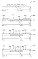
- the known humidity sensor 100 illustrated in FIG. 1 has a silicon substrate 101, a bottom electrode or lower electrode 102, which is formed by a suitably doped region in the silicon substrate 101, an overetched polymer layer 103 and a structured cover electrode 104 on. Air is applied to the polymer layer 103 via the structuring or openings of the structured cover electrode 104. The moisture contained in the air reaches the polymer layer 102 and influences its dielectric constant.
- the dielectric constant of the polymer layer 103 may be determined by the resistance formed by the lower electrode 102, the polymer layer 103 and the patterned lid electrode 104 forming a plate capacitor. The dielectric constant is used to determine the current humidity.
- the precursor 200 shown in FIG. 2 of a first embodiment of a moisture sensor according to the invention comprises a silicon substrate 101, a bottom electrode 102 formed by a doped region, a so-called intermediate layer deposited on the upper side of the silicon substrate 101 and the doped region 102 of silicon 201, a cover electrode formed by a doped region or upper electrode 202, and a masking of the upper surface of the intermediate layer 201 formed by a mask layer 203.
- the masking of the upper surface of the intermediate layer 201 is such that an etching opening 204 is formed over the lower electrode 102, the intermediate layer 201, and the upper electrode 202.
- the precursor 200 has been produced by known silicon semiconductor processes, so that it need not be discussed in detail.
- the precursor 200 shown in FIG. 2 is preferably introduced into an etching medium, which in particular has hydrofluoric acid. Between the top of the preamplifier 200 and the bottom of the preamplifier 200, an electrical voltage is applied. The electrical voltage causes a flow of current in the etching medium, the pores or openings in the cover electrode 202 and subsequently in the intermediate layer 201, each largely limited to the area below the etch opening 204 generated.
- the result of electrochemical etching using hydrofluoric acid is the first embodiment shown in FIG.
- porosity is meant in particular the ratio of cavity or space accessible from the outside, which is given by the pores formed in the respective areas, to the volume of the remaining material of the layer, based on one volume unit.
- the production of a cover electrode 202 is preferably achieved according to the invention in that the current intensity of the current flowing through the etching medium during the generation of the pores in the cover electrode 202 and subsequently during the generation of the pores in the underlying intermediate layer 201 is substantially identical. If necessary, when adjusting the current for generating the porosity in the cover electrode 202, it should be noted that the region 202 is doped differently from the intermediate layer 201.
- the depth of the porous etching is preferably predetermined at otherwise constant ⁇ tzparametern by the period during which the electric current flows through the etching medium.
- the humidity sensor of the present invention shown in Fig. 3 forms a capacitor having a porous thin upper electrode 202 and a porous region 301 in the intermediate layer 201 between the upper electrode 202 and the lower electrode 102.
- the porous region 301 of the intermediate layer 201 supports the upper electrode 202.
- moist air can enter the porous region 301 of the intermediate layer 201. This changes the dielectric constant and thus the evaluable capacitance between the upper and lower electrodes as a function of the specific humidity.
- the two electrodes can be electrically connected via doped regions in the form of printed conductors with contact pads or contact surfaces or with a circuit (not shown) integrated on the sensor.
- a reference capacitance can be made on the sensor, the z. B. is covered over the entire surface with metal in the subsequent metallization step. The cover can alternatively be made by a separately applied passivation. As a result, the reference capacity is no longer sensitive to moisture.
- FIG. 4 shows a second development of the preliminary stage of a first embodiment shown in FIG. 2.
- the moisture sensor according to the invention shown in FIG. 4 has a porosity in the region 401 of the upper electrode 202 or the upper intermediate layer 201, which clearly is less than the porosity of the intermediate layer 201 under the upper electrode 202.
- the upper electrode 202 or the corresponding, doped region which forms the upper electrode is etched in a porous manner by time-controlled application of an electrical voltage in hydrofluoric acid. It will worked with a low current density. This causes a low porosity.
- the intermediate layer 201 has been etched porous in the region of the upper electrode 202, the current density is significantly increased.
- the underlying intermediate layer is now also etched porous, but with a significantly higher porosity compared to the porosity of the upper electrode 202.
- the porous etched areas are bounded laterally by the mask layer 203.
- the intermediate layer 201 is significantly more porous than the doped region or the doped layer which forms the upper electrode 202 - as already explained.
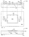
- FIG. 5 shows the exemplary embodiment of a moisture sensor 500 provided with electrical connections of FIGS. 3 or 4 in cross-section and in plan view.
- the lower electrode 102 is connected via a suitable, known through-connection 501 to a contact surface 502 for its external contacting.
- the upper electrode 202 is connected via a suitable, known contact track 504 to a contact surface 503 for its external contacting.
- the capacitance of the capacitor formed by the upper electrode 202, the lower electrode 102, and the porous layer 301 or 402 interposed therebetween is determined.
- the dielectric constant of the porous layer located between the two electrodes is of the specific medium dependent, which can penetrate from the outside into the pores of the porous layer.
- the dielectric constant of the porous layer depends on the concentration of the medium in question.
- atmospheric moisture penetrates through the porous upper electrode 202 into the porous region 301 or 402, so that the capacitance of the capacitor changes.
- This change is fed to an evaluation circuit (not shown) via the contact surfaces 502 and 503, which determines or quantitatively determines the change in capacitance and the altered atmospheric humidity that causes it.
- a reference capacitance can be used, which is also integrated on the capacitive sensor (not shown).
- Fig. 5 shows the moisture sensor 500 in cross section
- the humidity sensor 500 is shown in the lower part of Fig. 5 in plan view.
- the top view of the humidity sensor 500 can be taken that the lower electrode 102 and the upper electrode 202 have a rectangular outline and are arranged parallel offset in height. Their outlines are largely identical.
- the first variant 600 of a second embodiment of a humidity sensor according to the invention shown in FIG. 6 has two electrodes 601 and 602 arranged at the same height.
- the cross-section of the first variant or the capacitive sensor 600 shown in FIG. 6 shows that the first electrode 601 and the second electrode 602 are covered by a shielding electrode 603.
- the shielding electrode 603, the area of the intermediate layer 201 under the shielding electrode 603, and the area between the first electrode 601 and the second electrode 602 have been made porous in the manner described.
- the porous region (not shown) of the intermediate layer 201 and the porous region (not shown) between the electrodes 601 and 602 in the example of a humidity sensor presented here, atmospheric moisture passes between the first electrode 601 and the second electrode 602. Thereby, the permittivity of the porous region between the first electrode 601 and the second electrode 602 changes the capacity of the described capacitor changes. The change in capacity is evaluated in a known manner for the quantitative determination of the humidity.
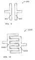
- FIG. 9 shows a first embodiment 900 for the electrodes shown in cross-section in FIG. 6, which form a plate capacitor.
- the plate capacitor 900 has a first bottom electrode 901 and a second bottom electrode 902.
- FIG. 10 shows a second embodiment of the electrodes shown in cross-section in FIG. These have the form of two intermeshing comb electrodes 1001 and 1002, which form a so-called interdigital structure 1000.
- the first and / or second electrode is or are at least partially formed by a suitably doped semiconductor layer and / or by a metallic layer.
Landscapes
- Chemical & Material Sciences (AREA)
- Chemical Kinetics & Catalysis (AREA)
- Electrochemistry (AREA)
- Physics & Mathematics (AREA)
- Health & Medical Sciences (AREA)
- Life Sciences & Earth Sciences (AREA)
- Analytical Chemistry (AREA)
- Biochemistry (AREA)
- General Health & Medical Sciences (AREA)
- General Physics & Mathematics (AREA)
- Immunology (AREA)
- Pathology (AREA)
- Investigating Or Analyzing Materials By The Use Of Electric Means (AREA)
- Investigating Or Analyzing Materials By The Use Of Fluid Adsorption Or Reactions (AREA)
Applications Claiming Priority (3)
| Application Number | Priority Date | Filing Date | Title |
|---|---|---|---|
| DE10134938 | 2001-07-18 | ||
| DE10134938A DE10134938A1 (de) | 2001-07-18 | 2001-07-18 | Halbleiterbauelement sowie ein Verfahren zur Herstellung des Halbleiterbauelements |
| PCT/DE2002/002481 WO2003009334A2 (de) | 2001-07-18 | 2002-07-06 | Halbleiterbauelement als kapazitiver feuchtesensor, sowie ein verfahren zur herstellung des halbleiterbauelements |
Publications (2)
| Publication Number | Publication Date |
|---|---|
| EP1412732A2 EP1412732A2 (de) | 2004-04-28 |
| EP1412732B1 true EP1412732B1 (de) | 2006-06-07 |
Family
ID=7692211
Family Applications (1)
| Application Number | Title | Priority Date | Filing Date |
|---|---|---|---|
| EP02754323A Expired - Lifetime EP1412732B1 (de) | 2001-07-18 | 2002-07-06 | Halbleiterbauelement als kapazitiver feuchtesensor, sowie ein verfahren zur herstellung des halbleiterbauelements |
Country Status (6)
| Country | Link |
|---|---|
| US (1) | US7193290B2 (enExample) |
| EP (1) | EP1412732B1 (enExample) |
| JP (1) | JP4227516B2 (enExample) |
| AT (1) | ATE329255T1 (enExample) |
| DE (2) | DE10134938A1 (enExample) |
| WO (1) | WO2003009334A2 (enExample) |
Families Citing this family (23)
| Publication number | Priority date | Publication date | Assignee | Title |
|---|---|---|---|---|
| US6931003B2 (en) * | 2000-02-09 | 2005-08-16 | Bookline Flolmstead Llc | Packet prioritization protocol for a large-scale, high speed computer network |
| US7110629B2 (en) * | 2002-07-22 | 2006-09-19 | Applied Materials, Inc. | Optical ready substrates |
| KR20060033721A (ko) * | 2003-05-29 | 2006-04-19 | 어플라이드 머티어리얼스, 인코포레이티드 | 내장형 도파관 검출기 |
| CN1795592A (zh) * | 2003-05-29 | 2006-06-28 | 应用材料股份有限公司 | 掺杂质基底的波导检测器 |
| US7205624B2 (en) * | 2003-10-07 | 2007-04-17 | Applied Materials, Inc. | Self-aligned implanted waveguide detector |
| US7368312B1 (en) * | 2004-10-15 | 2008-05-06 | Morgan Research Corporation | MEMS sensor suite on a chip |
| ITMO20050159A1 (it) * | 2005-06-22 | 2006-12-23 | Angelo Grandi Cucine Societa P | Sistema per il controllo dell'umidita'. |
| WO2007027615A1 (en) * | 2005-09-01 | 2007-03-08 | Applied Materials, Inc. | Ridge technique for fabricating an optical detector and an optical waveguide |
| WO2007057794A1 (en) * | 2005-11-17 | 2007-05-24 | Nxp B.V. | Moisture sensor |
| US7710128B2 (en) * | 2006-09-09 | 2010-05-04 | Honeywell International Inc. | Method and apparatus for controlling the sensitivity and value of a capacitive humidity sensor |
| DE202008003354U1 (de) | 2008-03-09 | 2008-05-15 | Hidde, Axel R., Dr. Ing. | Leckageüberwachung bei zylindrischen Anordnungen |
| KR101093612B1 (ko) | 2008-11-12 | 2011-12-15 | 전자부품연구원 | 정전용량형 습도센서 및 그 제조방법 |
| EP2336757B1 (en) * | 2009-12-07 | 2018-09-19 | ams international AG | Integrated circuit with water presence detection arrangement and manufacturing method therefor |
| CN103119429B (zh) * | 2010-05-06 | 2016-01-20 | 首尔大学校产学协力团 | 电容性元件传感器及其制造方法 |
| EP2693207A1 (en) * | 2012-07-30 | 2014-02-05 | Nxp B.V. | Integrated circuit comprising a capacitive gas sensor |
| DE102012108997A1 (de) * | 2012-09-24 | 2014-03-27 | Heinrich-Heine-Universität Düsseldorf | Sensoranordnung und Verfahren zum Herstellen einer Sensoranordnung |
| US8815054B2 (en) | 2012-10-05 | 2014-08-26 | The Procter & Gamble Company | Methods for making fibrous paper structures utilizing waterborne shape memory polymers |
| US9588073B2 (en) | 2012-12-19 | 2017-03-07 | Robert Bosch Gmbh | Resistive MEMS humidity sensor |
| EP2988122B1 (en) | 2014-08-20 | 2019-04-24 | ams international AG | Capacitive sensor |
| TWI601954B (zh) * | 2016-09-09 | 2017-10-11 | 長庚大學 | 電容式感濕元件及其使用方法 |
| KR102007446B1 (ko) * | 2018-05-21 | 2019-10-21 | 해성디에스 주식회사 | 센서 유닛, 이를 포함하는 온도 센서, 센서 유닛의 제조방법 및 이를 이용하여 제조된 온도 센서 |
| DE102018215018A1 (de) | 2018-09-04 | 2020-03-05 | Infineon Technologies Ag | Feuchtigkeitssensor |
| CN116854027A (zh) * | 2023-06-21 | 2023-10-10 | 北京大学 | 体硅内空腔结构及其制备方法 |
Citations (1)
| Publication number | Priority date | Publication date | Assignee | Title |
|---|---|---|---|---|
| GB2043908A (en) * | 1979-03-09 | 1980-10-08 | Moisture Control & Mesurement | Humidity Sensor Element |
Family Cites Families (8)
| Publication number | Priority date | Publication date | Assignee | Title |
|---|---|---|---|---|
| US4057823A (en) * | 1976-07-02 | 1977-11-08 | International Business Machines Corporation | Porous silicon dioxide moisture sensor and method for manufacture of a moisture sensor |
| US4277742A (en) * | 1977-01-31 | 1981-07-07 | Panametrics, Inc. | Absolute humidity sensors and methods of manufacturing humidity sensors |
| US4347550A (en) * | 1977-12-22 | 1982-08-31 | Peter Rockliff | Sensor detector element for an electrical hygrometer |
| US4356150A (en) * | 1981-05-15 | 1982-10-26 | Honeywell Inc. | Humidity sensor with electrical rejection of contaminants |
| US4795968A (en) * | 1986-06-30 | 1989-01-03 | Sri International | Gas detection method and apparatus using chemisorption and/or physisorption |
| US5332697A (en) * | 1989-05-31 | 1994-07-26 | Smith Rosemary L | Formation of silicon nitride by nitridation of porous silicon |
| GB9306594D0 (en) * | 1993-03-30 | 1993-05-26 | Univ Keele | Sensor |
| US6202471B1 (en) * | 1997-10-10 | 2001-03-20 | Nanomaterials Research Corporation | Low-cost multilaminate sensors |
-
2001
- 2001-07-18 DE DE10134938A patent/DE10134938A1/de not_active Withdrawn
-
2002
- 2002-07-06 AT AT02754323T patent/ATE329255T1/de not_active IP Right Cessation
- 2002-07-06 JP JP2003514583A patent/JP4227516B2/ja not_active Expired - Fee Related
- 2002-07-06 US US10/479,563 patent/US7193290B2/en not_active Expired - Lifetime
- 2002-07-06 EP EP02754323A patent/EP1412732B1/de not_active Expired - Lifetime
- 2002-07-06 WO PCT/DE2002/002481 patent/WO2003009334A2/de not_active Ceased
- 2002-07-06 DE DE50207120T patent/DE50207120D1/de not_active Expired - Lifetime
Patent Citations (1)
| Publication number | Priority date | Publication date | Assignee | Title |
|---|---|---|---|---|
| GB2043908A (en) * | 1979-03-09 | 1980-10-08 | Moisture Control & Mesurement | Humidity Sensor Element |
Also Published As
| Publication number | Publication date |
|---|---|
| US7193290B2 (en) | 2007-03-20 |
| JP4227516B2 (ja) | 2009-02-18 |
| US20040155751A1 (en) | 2004-08-12 |
| EP1412732A2 (de) | 2004-04-28 |
| JP2004535589A (ja) | 2004-11-25 |
| DE10134938A1 (de) | 2003-02-06 |
| WO2003009334A3 (de) | 2003-08-28 |
| DE50207120D1 (de) | 2006-07-20 |
| ATE329255T1 (de) | 2006-06-15 |
| WO2003009334A2 (de) | 2003-01-30 |
Similar Documents
| Publication | Publication Date | Title |
|---|---|---|
| EP1412732B1 (de) | Halbleiterbauelement als kapazitiver feuchtesensor, sowie ein verfahren zur herstellung des halbleiterbauelements | |
| DE3724966C2 (enExample) | ||
| DE60031089T2 (de) | Kapazitiver Drucksensor und zugehöriges Herstellungsverfahren | |
| DE69728577T2 (de) | Kapazitive sensoren zur messung der feuchtigkeit und deren verfahren zur herstellung | |
| DE3720189C1 (de) | Taupunkt-Sensor | |
| DE69318203T2 (de) | Kapazitiver Mikrosensor mit geringer parasitärer Kapazität und Verfahren zur dessen Herstellung | |
| WO2001042776A1 (de) | Kapazitiver sensor | |
| DE69408005T2 (de) | Halbleitervorrichtung mit piezoresistivem Druckwandler | |
| DE3833136A1 (de) | Kapazitives fuehlelement und verfahren zu seiner herstellung | |
| EP0684462A2 (de) | Thermischer Sensor/Aktuator in Hableitermaterial | |
| EP0801740B1 (de) | Elektrochemischer messfühler und verfahren zur herstellung eines elektrochemischen messfühlers | |
| WO2013072128A1 (de) | Integrierter feuchtesensor und verfahren zu dessen herstellung | |
| EP1115649B1 (de) | Mikromechanisches bauelement mit verschlossenen membranöffnungen | |
| EP0268768B1 (de) | Sensor zur Überwachung von Wasserstoffkonzentrationen in Gasen | |
| EP0082934B1 (de) | Feuchtigkeitsfühler und Verfahren zu seiner Herstellung | |
| DE19649366C2 (de) | Mikrosensor zur Flüssigkeitsanalyse, insbesondere von Alkohol-Benzin-Gemischen | |
| WO2004106879A1 (de) | Kapazitiver drucksensor | |
| DE102014210122A1 (de) | Vorrichtung zum Bestimmen eines Werts einer zu messenden Eigenschaft eines Fluids, Verfahren zum Betreiben einer Vorrichtung zum Bestimmen eines Werts einer zu messenden Eigenschaft eines Fluids sowie Verfahren zum Herstellen einer Vorrichtung zum Bestimmen eines Werts einer zu messenden Eigenschaft eines Fluids | |
| DE102015205384A1 (de) | Kapazitives MEMS-Sensorelement mit Bondpads zur elektrischen Kontaktierung der Messkondensatorelektroden | |
| EP0645621A2 (de) | Sensoranordnung | |
| DE102016207260B3 (de) | Mikromechanische Feuchtesensorvorrichtung und entsprechendes Herstellungsverfahren | |
| EP1169635B1 (de) | Elektrochemischer messfühler und verfahren zu dessen herstellung | |
| WO2003022732A2 (de) | Verfahren zur herstellung einer membran | |
| DE10246050A1 (de) | Vorrichtung und Verfahren | |
| DE102019130755A1 (de) | Sensorvorrichtung, Verfahren zum Herstellen einer Sensorvorrichtung und Sensorbaugruppe |
Legal Events
| Date | Code | Title | Description |
|---|---|---|---|
| PUAI | Public reference made under article 153(3) epc to a published international application that has entered the european phase |
Free format text: ORIGINAL CODE: 0009012 |
|
| 17P | Request for examination filed |
Effective date: 20040301 |
|
| AK | Designated contracting states |
Kind code of ref document: A2 Designated state(s): AT BE BG CH CY CZ DE DK EE ES FI FR GB GR IE IT LI LU MC NL PT SE SK TR |
|
| 17Q | First examination report despatched |
Effective date: 20040623 |
|
| GRAP | Despatch of communication of intention to grant a patent |
Free format text: ORIGINAL CODE: EPIDOSNIGR1 |
|
| GRAS | Grant fee paid |
Free format text: ORIGINAL CODE: EPIDOSNIGR3 |
|
| GRAA | (expected) grant |
Free format text: ORIGINAL CODE: 0009210 |
|
| AK | Designated contracting states |
Kind code of ref document: B1 Designated state(s): AT BE BG CH CY CZ DE DK EE ES FI FR GB GR IE IT LI LU MC NL PT SE SK TR |
|
| PG25 | Lapsed in a contracting state [announced via postgrant information from national office to epo] |
Ref country code: FI Free format text: LAPSE BECAUSE OF FAILURE TO SUBMIT A TRANSLATION OF THE DESCRIPTION OR TO PAY THE FEE WITHIN THE PRESCRIBED TIME-LIMIT Effective date: 20060607 Ref country code: IE Free format text: LAPSE BECAUSE OF FAILURE TO SUBMIT A TRANSLATION OF THE DESCRIPTION OR TO PAY THE FEE WITHIN THE PRESCRIBED TIME-LIMIT Effective date: 20060607 Ref country code: NL Free format text: LAPSE BECAUSE OF FAILURE TO SUBMIT A TRANSLATION OF THE DESCRIPTION OR TO PAY THE FEE WITHIN THE PRESCRIBED TIME-LIMIT Effective date: 20060607 Ref country code: CZ Free format text: LAPSE BECAUSE OF FAILURE TO SUBMIT A TRANSLATION OF THE DESCRIPTION OR TO PAY THE FEE WITHIN THE PRESCRIBED TIME-LIMIT Effective date: 20060607 Ref country code: SK Free format text: LAPSE BECAUSE OF FAILURE TO SUBMIT A TRANSLATION OF THE DESCRIPTION OR TO PAY THE FEE WITHIN THE PRESCRIBED TIME-LIMIT Effective date: 20060607 |
|
| REG | Reference to a national code |
Ref country code: GB Ref legal event code: FG4D Free format text: NOT ENGLISH |
|
| REG | Reference to a national code |
Ref country code: CH Ref legal event code: EP |
|
| REG | Reference to a national code |
Ref country code: IE Ref legal event code: FG4D Free format text: LANGUAGE OF EP DOCUMENT: GERMAN |
|
| REF | Corresponds to: |
Ref document number: 50207120 Country of ref document: DE Date of ref document: 20060720 Kind code of ref document: P |
|
| PG25 | Lapsed in a contracting state [announced via postgrant information from national office to epo] |
Ref country code: LI Free format text: LAPSE BECAUSE OF NON-PAYMENT OF DUE FEES Effective date: 20060731 Ref country code: MC Free format text: LAPSE BECAUSE OF NON-PAYMENT OF DUE FEES Effective date: 20060731 Ref country code: BE Free format text: LAPSE BECAUSE OF NON-PAYMENT OF DUE FEES Effective date: 20060731 Ref country code: CH Free format text: LAPSE BECAUSE OF NON-PAYMENT OF DUE FEES Effective date: 20060731 |
|
| PG25 | Lapsed in a contracting state [announced via postgrant information from national office to epo] |
Ref country code: DK Free format text: LAPSE BECAUSE OF FAILURE TO SUBMIT A TRANSLATION OF THE DESCRIPTION OR TO PAY THE FEE WITHIN THE PRESCRIBED TIME-LIMIT Effective date: 20060907 Ref country code: SE Free format text: LAPSE BECAUSE OF FAILURE TO SUBMIT A TRANSLATION OF THE DESCRIPTION OR TO PAY THE FEE WITHIN THE PRESCRIBED TIME-LIMIT Effective date: 20060907 |
|
| PG25 | Lapsed in a contracting state [announced via postgrant information from national office to epo] |
Ref country code: ES Free format text: LAPSE BECAUSE OF FAILURE TO SUBMIT A TRANSLATION OF THE DESCRIPTION OR TO PAY THE FEE WITHIN THE PRESCRIBED TIME-LIMIT Effective date: 20060918 |
|
| GBT | Gb: translation of ep patent filed (gb section 77(6)(a)/1977) |
Effective date: 20060923 |
|
| PG25 | Lapsed in a contracting state [announced via postgrant information from national office to epo] |
Ref country code: PT Free format text: LAPSE BECAUSE OF FAILURE TO SUBMIT A TRANSLATION OF THE DESCRIPTION OR TO PAY THE FEE WITHIN THE PRESCRIBED TIME-LIMIT Effective date: 20061107 |
|
| NLV1 | Nl: lapsed or annulled due to failure to fulfill the requirements of art. 29p and 29m of the patents act | ||
| ET | Fr: translation filed | ||
| REG | Reference to a national code |
Ref country code: IE Ref legal event code: FD4D |
|
| REG | Reference to a national code |
Ref country code: CH Ref legal event code: PL |
|
| PLBE | No opposition filed within time limit |
Free format text: ORIGINAL CODE: 0009261 |
|
| STAA | Information on the status of an ep patent application or granted ep patent |
Free format text: STATUS: NO OPPOSITION FILED WITHIN TIME LIMIT |
|
| 26N | No opposition filed |
Effective date: 20070308 |
|
| PG25 | Lapsed in a contracting state [announced via postgrant information from national office to epo] |
Ref country code: AT Free format text: LAPSE BECAUSE OF NON-PAYMENT OF DUE FEES Effective date: 20060706 |
|
| BERE | Be: lapsed |
Owner name: ROBERT BOSCH G.M.B.H. Effective date: 20060731 |
|
| PG25 | Lapsed in a contracting state [announced via postgrant information from national office to epo] |
Ref country code: GR Free format text: LAPSE BECAUSE OF FAILURE TO SUBMIT A TRANSLATION OF THE DESCRIPTION OR TO PAY THE FEE WITHIN THE PRESCRIBED TIME-LIMIT Effective date: 20060908 |
|
| PG25 | Lapsed in a contracting state [announced via postgrant information from national office to epo] |
Ref country code: EE Free format text: LAPSE BECAUSE OF FAILURE TO SUBMIT A TRANSLATION OF THE DESCRIPTION OR TO PAY THE FEE WITHIN THE PRESCRIBED TIME-LIMIT Effective date: 20060607 Ref country code: BG Free format text: LAPSE BECAUSE OF FAILURE TO SUBMIT A TRANSLATION OF THE DESCRIPTION OR TO PAY THE FEE WITHIN THE PRESCRIBED TIME-LIMIT Effective date: 20060907 |
|
| PG25 | Lapsed in a contracting state [announced via postgrant information from national office to epo] |
Ref country code: LU Free format text: LAPSE BECAUSE OF NON-PAYMENT OF DUE FEES Effective date: 20060706 Ref country code: TR Free format text: LAPSE BECAUSE OF FAILURE TO SUBMIT A TRANSLATION OF THE DESCRIPTION OR TO PAY THE FEE WITHIN THE PRESCRIBED TIME-LIMIT Effective date: 20060607 |
|
| PG25 | Lapsed in a contracting state [announced via postgrant information from national office to epo] |
Ref country code: CY Free format text: LAPSE BECAUSE OF FAILURE TO SUBMIT A TRANSLATION OF THE DESCRIPTION OR TO PAY THE FEE WITHIN THE PRESCRIBED TIME-LIMIT Effective date: 20060607 |
|
| REG | Reference to a national code |
Ref country code: FR Ref legal event code: PLFP Year of fee payment: 15 |
|
| REG | Reference to a national code |
Ref country code: FR Ref legal event code: PLFP Year of fee payment: 16 |
|
| PGFP | Annual fee paid to national office [announced via postgrant information from national office to epo] |
Ref country code: FR Payment date: 20170720 Year of fee payment: 16 Ref country code: GB Payment date: 20170724 Year of fee payment: 16 Ref country code: IT Payment date: 20170721 Year of fee payment: 16 |
|
| GBPC | Gb: european patent ceased through non-payment of renewal fee |
Effective date: 20180706 |
|
| PG25 | Lapsed in a contracting state [announced via postgrant information from national office to epo] |
Ref country code: GB Free format text: LAPSE BECAUSE OF NON-PAYMENT OF DUE FEES Effective date: 20180706 Ref country code: FR Free format text: LAPSE BECAUSE OF NON-PAYMENT OF DUE FEES Effective date: 20180731 |
|
| PG25 | Lapsed in a contracting state [announced via postgrant information from national office to epo] |
Ref country code: IT Free format text: LAPSE BECAUSE OF NON-PAYMENT OF DUE FEES Effective date: 20180706 |
|
| PGFP | Annual fee paid to national office [announced via postgrant information from national office to epo] |
Ref country code: DE Payment date: 20190924 Year of fee payment: 18 |
|
| REG | Reference to a national code |
Ref country code: DE Ref legal event code: R119 Ref document number: 50207120 Country of ref document: DE |
|
| PG25 | Lapsed in a contracting state [announced via postgrant information from national office to epo] |
Ref country code: DE Free format text: LAPSE BECAUSE OF NON-PAYMENT OF DUE FEES Effective date: 20210202 |