EP1412003B1 - Dispositifs servant a administrer une perfusion intraveineuse - Google Patents
Dispositifs servant a administrer une perfusion intraveineuse Download PDFInfo
- Publication number
- EP1412003B1 EP1412003B1 EP02756778A EP02756778A EP1412003B1 EP 1412003 B1 EP1412003 B1 EP 1412003B1 EP 02756778 A EP02756778 A EP 02756778A EP 02756778 A EP02756778 A EP 02756778A EP 1412003 B1 EP1412003 B1 EP 1412003B1
- Authority
- EP
- European Patent Office
- Prior art keywords
- infusate
- cassette
- container
- infusion
- patient
- Prior art date
- Legal status (The legal status is an assumption and is not a legal conclusion. Google has not performed a legal analysis and makes no representation as to the accuracy of the status listed.)
- Expired - Lifetime
Links
- 238000001802 infusion Methods 0.000 title claims abstract description 124
- 230000007246 mechanism Effects 0.000 claims abstract description 88
- 239000003814 drug Substances 0.000 claims abstract description 44
- 229940079593 drug Drugs 0.000 claims abstract description 44
- 238000000034 method Methods 0.000 claims abstract description 35
- 238000000275 quality assurance Methods 0.000 claims abstract description 8
- 230000004913 activation Effects 0.000 claims description 15
- 238000004891 communication Methods 0.000 claims description 15
- 206010039897 Sedation Diseases 0.000 claims description 7
- 230000036280 sedation Effects 0.000 claims description 7
- 230000000694 effects Effects 0.000 claims description 5
- 230000004962 physiological condition Effects 0.000 claims description 5
- 238000012377 drug delivery Methods 0.000 claims description 4
- 230000036541 health Effects 0.000 claims description 4
- 238000012546 transfer Methods 0.000 claims description 4
- 230000000977 initiatory effect Effects 0.000 claims description 3
- 238000005259 measurement Methods 0.000 claims description 2
- 230000008093 supporting effect Effects 0.000 claims description 2
- 239000000932 sedative agent Substances 0.000 claims 5
- 230000001624 sedative effect Effects 0.000 claims 5
- 230000008569 process Effects 0.000 abstract description 21
- 238000010926 purge Methods 0.000 abstract description 21
- 238000005336 cracking Methods 0.000 abstract description 4
- 239000003570 air Substances 0.000 description 59
- 238000005086 pumping Methods 0.000 description 50
- 230000013011 mating Effects 0.000 description 25
- 239000007788 liquid Substances 0.000 description 15
- 230000002572 peristaltic effect Effects 0.000 description 13
- 239000012530 fluid Substances 0.000 description 9
- 230000005499 meniscus Effects 0.000 description 9
- 238000001990 intravenous administration Methods 0.000 description 7
- 230000002265 prevention Effects 0.000 description 7
- 230000000241 respiratory effect Effects 0.000 description 7
- 230000002792 vascular Effects 0.000 description 7
- 238000010586 diagram Methods 0.000 description 6
- 208000012266 Needlestick injury Diseases 0.000 description 5
- 230000009471 action Effects 0.000 description 5
- 230000036592 analgesia Effects 0.000 description 5
- 238000013461 design Methods 0.000 description 5
- 230000005484 gravity Effects 0.000 description 5
- 239000007924 injection Substances 0.000 description 5
- 238000002347 injection Methods 0.000 description 5
- 230000000151 anti-reflux effect Effects 0.000 description 4
- 230000033001 locomotion Effects 0.000 description 4
- 231100000279 safety data Toxicity 0.000 description 4
- QVGXLLKOCUKJST-UHFFFAOYSA-N atomic oxygen Chemical compound [O] QVGXLLKOCUKJST-UHFFFAOYSA-N 0.000 description 3
- 238000012864 cross contamination Methods 0.000 description 3
- 238000012544 monitoring process Methods 0.000 description 3
- 230000003287 optical effect Effects 0.000 description 3
- 239000001301 oxygen Substances 0.000 description 3
- 229910052760 oxygen Inorganic materials 0.000 description 3
- 230000004043 responsiveness Effects 0.000 description 3
- 210000003462 vein Anatomy 0.000 description 3
- 230000009286 beneficial effect Effects 0.000 description 2
- 230000008859 change Effects 0.000 description 2
- 238000011109 contamination Methods 0.000 description 2
- 230000007423 decrease Effects 0.000 description 2
- 230000000994 depressogenic effect Effects 0.000 description 2
- 238000006073 displacement reaction Methods 0.000 description 2
- 239000006260 foam Substances 0.000 description 2
- 239000007789 gas Substances 0.000 description 2
- 230000002209 hydrophobic effect Effects 0.000 description 2
- 230000002706 hydrostatic effect Effects 0.000 description 2
- 238000003384 imaging method Methods 0.000 description 2
- 230000001939 inductive effect Effects 0.000 description 2
- 239000003978 infusion fluid Substances 0.000 description 2
- 208000014674 injury Diseases 0.000 description 2
- 230000003993 interaction Effects 0.000 description 2
- 238000007726 management method Methods 0.000 description 2
- 238000004519 manufacturing process Methods 0.000 description 2
- BQJCRHHNABKAKU-KBQPJGBKSA-N morphine Chemical compound O([C@H]1[C@H](C=C[C@H]23)O)C4=C5[C@@]12CCN(C)[C@@H]3CC5=CC=C4O BQJCRHHNABKAKU-KBQPJGBKSA-N 0.000 description 2
- 239000004033 plastic Substances 0.000 description 2
- 230000037452 priming Effects 0.000 description 2
- OLBCVFGFOZPWHH-UHFFFAOYSA-N propofol Chemical compound CC(C)C1=CC=CC(C(C)C)=C1O OLBCVFGFOZPWHH-UHFFFAOYSA-N 0.000 description 2
- 229960004134 propofol Drugs 0.000 description 2
- 238000003908 quality control method Methods 0.000 description 2
- 238000005070 sampling Methods 0.000 description 2
- 238000007789 sealing Methods 0.000 description 2
- 239000007779 soft material Substances 0.000 description 2
- 239000000243 solution Substances 0.000 description 2
- 230000001960 triggered effect Effects 0.000 description 2
- 238000013022 venting Methods 0.000 description 2
- 208000012260 Accidental injury Diseases 0.000 description 1
- 206010002091 Anaesthesia Diseases 0.000 description 1
- 230000005355 Hall effect Effects 0.000 description 1
- 206010020751 Hypersensitivity Diseases 0.000 description 1
- 208000003443 Unconsciousness Diseases 0.000 description 1
- 208000027418 Wounds and injury Diseases 0.000 description 1
- 230000007815 allergy Effects 0.000 description 1
- 239000012080 ambient air Substances 0.000 description 1
- 230000037005 anaesthesia Effects 0.000 description 1
- 238000004873 anchoring Methods 0.000 description 1
- 208000008784 apnea Diseases 0.000 description 1
- 238000003491 array Methods 0.000 description 1
- 230000001580 bacterial effect Effects 0.000 description 1
- 230000008901 benefit Effects 0.000 description 1
- 230000005540 biological transmission Effects 0.000 description 1
- 230000015572 biosynthetic process Effects 0.000 description 1
- 230000017531 blood circulation Effects 0.000 description 1
- 230000036772 blood pressure Effects 0.000 description 1
- 238000004364 calculation method Methods 0.000 description 1
- 230000000747 cardiac effect Effects 0.000 description 1
- 230000001010 compromised effect Effects 0.000 description 1
- 239000000356 contaminant Substances 0.000 description 1
- 230000006378 damage Effects 0.000 description 1
- 230000009849 deactivation Effects 0.000 description 1
- 230000034994 death Effects 0.000 description 1
- 231100000517 death Toxicity 0.000 description 1
- 238000004925 denaturation Methods 0.000 description 1
- 230000036425 denaturation Effects 0.000 description 1
- 238000004945 emulsification Methods 0.000 description 1
- 238000001704 evaporation Methods 0.000 description 1
- 230000008020 evaporation Effects 0.000 description 1
- 230000002496 gastric effect Effects 0.000 description 1
- 238000003780 insertion Methods 0.000 description 1
- 230000037431 insertion Effects 0.000 description 1
- 230000005291 magnetic effect Effects 0.000 description 1
- 239000000463 material Substances 0.000 description 1
- 239000002184 metal Substances 0.000 description 1
- 230000000813 microbial effect Effects 0.000 description 1
- 239000002991 molded plastic Substances 0.000 description 1
- 238000012806 monitoring device Methods 0.000 description 1
- 229960005181 morphine Drugs 0.000 description 1
- 238000004806 packaging method and process Methods 0.000 description 1
- 230000036407 pain Effects 0.000 description 1
- 239000002245 particle Substances 0.000 description 1
- 244000052769 pathogen Species 0.000 description 1
- 230000037361 pathway Effects 0.000 description 1
- 230000000737 periodic effect Effects 0.000 description 1
- 230000003389 potentiating effect Effects 0.000 description 1
- 230000004044 response Effects 0.000 description 1
- 230000000284 resting effect Effects 0.000 description 1
- 238000012216 screening Methods 0.000 description 1
- 238000000926 separation method Methods 0.000 description 1
- 239000002904 solvent Substances 0.000 description 1
- -1 supplies Substances 0.000 description 1
- 238000001356 surgical procedure Methods 0.000 description 1
- 230000001225 therapeutic effect Effects 0.000 description 1
- 230000007704 transition Effects 0.000 description 1
- 239000013598 vector Substances 0.000 description 1
- 230000003612 virological effect Effects 0.000 description 1
- 230000000007 visual effect Effects 0.000 description 1
Images


Classifications
-
- A—HUMAN NECESSITIES
- A61—MEDICAL OR VETERINARY SCIENCE; HYGIENE
- A61M—DEVICES FOR INTRODUCING MEDIA INTO, OR ONTO, THE BODY; DEVICES FOR TRANSDUCING BODY MEDIA OR FOR TAKING MEDIA FROM THE BODY; DEVICES FOR PRODUCING OR ENDING SLEEP OR STUPOR
- A61M39/00—Tubes, tube connectors, tube couplings, valves, access sites or the like, specially adapted for medical use
- A61M39/22—Valves or arrangement of valves
- A61M39/28—Clamping means for squeezing flexible tubes, e.g. roller clamps
- A61M39/281—Automatic tube cut-off devices, e.g. squeezing tube on detection of air
-
- A—HUMAN NECESSITIES
- A61—MEDICAL OR VETERINARY SCIENCE; HYGIENE
- A61M—DEVICES FOR INTRODUCING MEDIA INTO, OR ONTO, THE BODY; DEVICES FOR TRANSDUCING BODY MEDIA OR FOR TAKING MEDIA FROM THE BODY; DEVICES FOR PRODUCING OR ENDING SLEEP OR STUPOR
- A61M5/00—Devices for bringing media into the body in a subcutaneous, intra-vascular or intramuscular way; Accessories therefor, e.g. filling or cleaning devices, arm-rests
- A61M5/14—Infusion devices, e.g. infusing by gravity; Blood infusion; Accessories therefor
- A61M5/142—Pressure infusion, e.g. using pumps
-
- A—HUMAN NECESSITIES
- A61—MEDICAL OR VETERINARY SCIENCE; HYGIENE
- A61M—DEVICES FOR INTRODUCING MEDIA INTO, OR ONTO, THE BODY; DEVICES FOR TRANSDUCING BODY MEDIA OR FOR TAKING MEDIA FROM THE BODY; DEVICES FOR PRODUCING OR ENDING SLEEP OR STUPOR
- A61M5/00—Devices for bringing media into the body in a subcutaneous, intra-vascular or intramuscular way; Accessories therefor, e.g. filling or cleaning devices, arm-rests
- A61M5/14—Infusion devices, e.g. infusing by gravity; Blood infusion; Accessories therefor
- A61M5/162—Needle sets, i.e. connections by puncture between reservoir and tube ; Connections between reservoir and tube
-
- G—PHYSICS
- G16—INFORMATION AND COMMUNICATION TECHNOLOGY [ICT] SPECIALLY ADAPTED FOR SPECIFIC APPLICATION FIELDS
- G16H—HEALTHCARE INFORMATICS, i.e. INFORMATION AND COMMUNICATION TECHNOLOGY [ICT] SPECIALLY ADAPTED FOR THE HANDLING OR PROCESSING OF MEDICAL OR HEALTHCARE DATA
- G16H20/00—ICT specially adapted for therapies or health-improving plans, e.g. for handling prescriptions, for steering therapy or for monitoring patient compliance
- G16H20/10—ICT specially adapted for therapies or health-improving plans, e.g. for handling prescriptions, for steering therapy or for monitoring patient compliance relating to drugs or medications, e.g. for ensuring correct administration to patients
- G16H20/17—ICT specially adapted for therapies or health-improving plans, e.g. for handling prescriptions, for steering therapy or for monitoring patient compliance relating to drugs or medications, e.g. for ensuring correct administration to patients delivered via infusion or injection
-
- A—HUMAN NECESSITIES
- A61—MEDICAL OR VETERINARY SCIENCE; HYGIENE
- A61M—DEVICES FOR INTRODUCING MEDIA INTO, OR ONTO, THE BODY; DEVICES FOR TRANSDUCING BODY MEDIA OR FOR TAKING MEDIA FROM THE BODY; DEVICES FOR PRODUCING OR ENDING SLEEP OR STUPOR
- A61M5/00—Devices for bringing media into the body in a subcutaneous, intra-vascular or intramuscular way; Accessories therefor, e.g. filling or cleaning devices, arm-rests
- A61M5/14—Infusion devices, e.g. infusing by gravity; Blood infusion; Accessories therefor
- A61M2005/1401—Functional features
- A61M2005/1402—Priming
-
- A—HUMAN NECESSITIES
- A61—MEDICAL OR VETERINARY SCIENCE; HYGIENE
- A61M—DEVICES FOR INTRODUCING MEDIA INTO, OR ONTO, THE BODY; DEVICES FOR TRANSDUCING BODY MEDIA OR FOR TAKING MEDIA FROM THE BODY; DEVICES FOR PRODUCING OR ENDING SLEEP OR STUPOR
- A61M5/00—Devices for bringing media into the body in a subcutaneous, intra-vascular or intramuscular way; Accessories therefor, e.g. filling or cleaning devices, arm-rests
- A61M5/14—Infusion devices, e.g. infusing by gravity; Blood infusion; Accessories therefor
- A61M5/142—Pressure infusion, e.g. using pumps
- A61M2005/14208—Pressure infusion, e.g. using pumps with a programmable infusion control system, characterised by the infusion program
-
- A—HUMAN NECESSITIES
- A61—MEDICAL OR VETERINARY SCIENCE; HYGIENE
- A61M—DEVICES FOR INTRODUCING MEDIA INTO, OR ONTO, THE BODY; DEVICES FOR TRANSDUCING BODY MEDIA OR FOR TAKING MEDIA FROM THE BODY; DEVICES FOR PRODUCING OR ENDING SLEEP OR STUPOR
- A61M5/00—Devices for bringing media into the body in a subcutaneous, intra-vascular or intramuscular way; Accessories therefor, e.g. filling or cleaning devices, arm-rests
- A61M5/14—Infusion devices, e.g. infusing by gravity; Blood infusion; Accessories therefor
- A61M5/162—Needle sets, i.e. connections by puncture between reservoir and tube ; Connections between reservoir and tube
- A61M2005/1623—Details of air intake
-
- A—HUMAN NECESSITIES
- A61—MEDICAL OR VETERINARY SCIENCE; HYGIENE
- A61M—DEVICES FOR INTRODUCING MEDIA INTO, OR ONTO, THE BODY; DEVICES FOR TRANSDUCING BODY MEDIA OR FOR TAKING MEDIA FROM THE BODY; DEVICES FOR PRODUCING OR ENDING SLEEP OR STUPOR
- A61M2205/00—General characteristics of the apparatus
- A61M2205/12—General characteristics of the apparatus with interchangeable cassettes forming partially or totally the fluid circuit
-
- A—HUMAN NECESSITIES
- A61—MEDICAL OR VETERINARY SCIENCE; HYGIENE
- A61M—DEVICES FOR INTRODUCING MEDIA INTO, OR ONTO, THE BODY; DEVICES FOR TRANSDUCING BODY MEDIA OR FOR TAKING MEDIA FROM THE BODY; DEVICES FOR PRODUCING OR ENDING SLEEP OR STUPOR
- A61M2205/00—General characteristics of the apparatus
- A61M2205/33—Controlling, regulating or measuring
- A61M2205/3379—Masses, volumes, levels of fluids in reservoirs, flow rates
- A61M2205/3386—Low level detectors
-
- A—HUMAN NECESSITIES
- A61—MEDICAL OR VETERINARY SCIENCE; HYGIENE
- A61M—DEVICES FOR INTRODUCING MEDIA INTO, OR ONTO, THE BODY; DEVICES FOR TRANSDUCING BODY MEDIA OR FOR TAKING MEDIA FROM THE BODY; DEVICES FOR PRODUCING OR ENDING SLEEP OR STUPOR
- A61M2205/00—General characteristics of the apparatus
- A61M2205/35—Communication
- A61M2205/3546—Range
- A61M2205/3553—Range remote, e.g. between patient's home and doctor's office
-
- A—HUMAN NECESSITIES
- A61—MEDICAL OR VETERINARY SCIENCE; HYGIENE
- A61M—DEVICES FOR INTRODUCING MEDIA INTO, OR ONTO, THE BODY; DEVICES FOR TRANSDUCING BODY MEDIA OR FOR TAKING MEDIA FROM THE BODY; DEVICES FOR PRODUCING OR ENDING SLEEP OR STUPOR
- A61M2205/00—General characteristics of the apparatus
- A61M2205/60—General characteristics of the apparatus with identification means
- A61M2205/6045—General characteristics of the apparatus with identification means having complementary physical shapes for indexing or registration purposes
-
- A—HUMAN NECESSITIES
- A61—MEDICAL OR VETERINARY SCIENCE; HYGIENE
- A61M—DEVICES FOR INTRODUCING MEDIA INTO, OR ONTO, THE BODY; DEVICES FOR TRANSDUCING BODY MEDIA OR FOR TAKING MEDIA FROM THE BODY; DEVICES FOR PRODUCING OR ENDING SLEEP OR STUPOR
- A61M2205/00—General characteristics of the apparatus
- A61M2205/60—General characteristics of the apparatus with identification means
- A61M2205/6054—Magnetic identification systems
-
- A—HUMAN NECESSITIES
- A61—MEDICAL OR VETERINARY SCIENCE; HYGIENE
- A61M—DEVICES FOR INTRODUCING MEDIA INTO, OR ONTO, THE BODY; DEVICES FOR TRANSDUCING BODY MEDIA OR FOR TAKING MEDIA FROM THE BODY; DEVICES FOR PRODUCING OR ENDING SLEEP OR STUPOR
- A61M5/00—Devices for bringing media into the body in a subcutaneous, intra-vascular or intramuscular way; Accessories therefor, e.g. filling or cleaning devices, arm-rests
- A61M5/14—Infusion devices, e.g. infusing by gravity; Blood infusion; Accessories therefor
- A61M5/142—Pressure infusion, e.g. using pumps
- A61M5/14212—Pumping with an aspiration and an expulsion action
- A61M5/14228—Pumping with an aspiration and an expulsion action with linear peristaltic action, i.e. comprising at least three pressurising members or a helical member
-
- A—HUMAN NECESSITIES
- A61—MEDICAL OR VETERINARY SCIENCE; HYGIENE
- A61M—DEVICES FOR INTRODUCING MEDIA INTO, OR ONTO, THE BODY; DEVICES FOR TRANSDUCING BODY MEDIA OR FOR TAKING MEDIA FROM THE BODY; DEVICES FOR PRODUCING OR ENDING SLEEP OR STUPOR
- A61M5/00—Devices for bringing media into the body in a subcutaneous, intra-vascular or intramuscular way; Accessories therefor, e.g. filling or cleaning devices, arm-rests
- A61M5/14—Infusion devices, e.g. infusing by gravity; Blood infusion; Accessories therefor
- A61M5/142—Pressure infusion, e.g. using pumps
- A61M5/14212—Pumping with an aspiration and an expulsion action
- A61M5/14232—Roller pumps
-
- A—HUMAN NECESSITIES
- A61—MEDICAL OR VETERINARY SCIENCE; HYGIENE
- A61M—DEVICES FOR INTRODUCING MEDIA INTO, OR ONTO, THE BODY; DEVICES FOR TRANSDUCING BODY MEDIA OR FOR TAKING MEDIA FROM THE BODY; DEVICES FOR PRODUCING OR ENDING SLEEP OR STUPOR
- A61M5/00—Devices for bringing media into the body in a subcutaneous, intra-vascular or intramuscular way; Accessories therefor, e.g. filling or cleaning devices, arm-rests
- A61M5/14—Infusion devices, e.g. infusing by gravity; Blood infusion; Accessories therefor
- A61M5/168—Means for controlling media flow to the body or for metering media to the body, e.g. drip meters, counters ; Monitoring media flow to the body
- A61M5/172—Means for controlling media flow to the body or for metering media to the body, e.g. drip meters, counters ; Monitoring media flow to the body electrical or electronic
- A61M5/1723—Means for controlling media flow to the body or for metering media to the body, e.g. drip meters, counters ; Monitoring media flow to the body electrical or electronic using feedback of body parameters, e.g. blood-sugar, pressure
Definitions
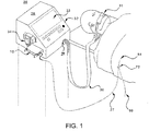
- the invention of this application relates generally to IV infusion of drugs to patients, and more particularly to aspects of an IV infusion system comprising an infusate cassette, an infusate container, and various quality assurance means.
- Certain known medical devices for controlling the infusion of a liquid directly to a patient utilize pumping mechanisms to deliver liquid drugs from a reservoir such as a syringe, a collapsible bag, or a drug container to a patient supply tube.
- a reservoir such as a syringe, a collapsible bag, or a drug container
- a device shown in U.S. Pat. No. 6,186,977 , includes a liquid drug supply in a collapsible bag and an infusion pump, which draws the drug directly from the supply and moves it along a flow passage to a patient supply tube.
- Certain of these medical devices further utilize drug pump cassettes, which provide a rigid housing and pressure plate that interact with the pumping mechanisms of the devices. These cassettes serve as intermediary devices between drug containers and patient supply lines.
- a typical cassette includes a passage, which is acted upon by the pumping mechanism of an infusion device to move the drug along to the supply line.
- a cassette for use with a drug pumping system shown in U.S. Pat. No. 6,165,154 , has a fluid passage and a collapsible pressure conduction chamber for generating a pressure gradient to move drug along the passage.
- Another example of a cassette shown in U.S. Pat. No. 6,202,708 , provides a large chamber for mixing a powdered drug with a liquid solvent.
- This cassette also includes a pressure plate, which supports a fluid flow passage against which a peristaltic pump may act to move the liquid along to a patient delivery tube.
- Certain liquid infusion devices which provide means for removing air that has entered their flow passages are also known.
- these devices often require an inefficient purging process which in turn requires human intervention and/or knowledge of the exact internal volume of all of the liquid passages in the system in order to flush air from the passages without losing excessive amounts of the drug.
- Another drawback of the above devices is that certain of their components, such as the drug containers, cannot be replaced during an infusion process, i.e., while the pumping mechanism is active, without introducing air into the system. Air may also be introduced into the systems if these components are accidentally removed from the device during an infusion process. Air bubbles that are entrained into the flow passages of a direct-to-patient infusion system can be dangerous if introduced into the patient's circulatory system.
- a means of controlling the infusion rate of a drug based on a measurement or inference of an effect of the delivered drug on the patient may be beneficial.
- Such a means of control may be especially desirable during outpatient, ambulatory, gastrointestinal, cardiac catheterization, imaging and other procedures at remote and/or minimally staffed or equipped locations such as, among others, office-based surgery, imaging, or dermatology suites and far-forward military medical outposts where anesthesia and analgesia are provided with the concomitant risk of loss of consciousness and apnea.
- US-A-6,063,052 and US-A-5,431,627 disclose care systems comprising an infusion pump according to the preamble of claim 1.
- the present invention is defined in claim 1. It addresses the aforementioned drawbacks of existing drug infusion devices by providing an infusion system with an infusate pump cassette that may include disposable components, external redundant volume tracking, air removal and automated purge and prime capabilities, component lockout mechanisms, and/or redundant automated anti-free flow devices.
- infusion system as it is used herein may denote a stand-alone infusion pump that is not necessarily integrated with patient monitoring.
- Components of this aspect of the invention that may be disposable may include, among other items, infusate containers, infusion tubing, pressure plates, infusion line connectors, cassettes, anti-reflux valves, high cracking pressure valves, IV manifolds and vascular access devices such as, among others, IV needles, cannulae and catheters.
- the infusion system of the present invention may form part of a larger infusion system for computer assisted infusate administration that may include EKG pads or skin electrodes, and oxygen delivery, gas sampling and respiratory apparatuses, responsiveness query devices, and semi-automated modulation of infusion rate based on measured or inferred effects on the patient.
- the EKG pads or skin electrodes, oxygen delivery, gas sampling and respiratory apparatuses and responsiveness query devices may be disposable.
- the term "infusion system" as it is used herein may denote an infusion pump integrated into a larger system that manages the administration of infusate based on data from patient monitoring devices.
- the integrated computer assisted infusate administration system is applicable for use in, among others, sedation and analgesia and deep sedation procedures.
- An example of such a system could be the sedation and analgesia delivery system described in U.S. Patent Application Serial No. 09/324,759 filed June 3, 1999 , and published as U.S. Patent 6,807,965 .
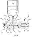
- FIG. 3 shows a cassette 10 for the transfer of infusate from infusate container 34 (which may be sealed) to a patient.
- the cassette 10 provides a mechanical platform for anchoring infusate container 34 to the housing 26 and assures that the infusate container 34 remains at a fixed head height with respect to pumping mechanism 56.
- the cassette 10 also assures that delivery conduit 27 is positioned and oriented properly with respect to pumping mechanism 56.
- the cassette includes an extension 11 for receiving the infusate container 34 and maintaining the container's position during the infusion process.
- the cassette 10 receives a single infusate container 34 for each infusion process. At the conclusion of the infusion process or upon the near-depletion of the container 34, the container 34 is removed and' the cassette 10 may receive a new infusate container 34 for an extension of a prior infusion process.
- the delivery conduit 27 may be purged of any air and/or infusate from the prior infusion process.
- the cassette 10 may receive more than one infusate container 34 at a time.
- the cassette 10 may have multiple flow lumens (e.g., such as those shown in FIG.
- a mechanism may be provided to restrict the infusate flow created by the pumping mechanism 56 so that infusate flows from one infusate container 34 at a time for a sequential sequence or from more than one infusate container 34 at a time according to pre-determined proportions.
- Pumping infusate from multiple containers simultaneously allows an extended infusion run without halting for a purge sequence. Pumping infusate from multiple containers in concert allows separate and segregated sources of infusate to be used concurrently for a single infusion run.
- multiple containers of the same infusate are provided with a single cassette 10 such that one container can be removed while infusate is flowing from another. Such an embodiment allows for an extended infusion process without halting for a purge sequence.
- the extension 11 may include an attached infusate flow activation device 12 (which as further described below may be a spike or other sharp having internal lumens) for initiating the transfer of the infusate from the infusate container 34 to delivery conduit 27.
- an attached infusate flow activation device 12 (which as further described below may be a spike or other sharp having internal lumens) for initiating the transfer of the infusate from the infusate container 34 to delivery conduit 27.
- the infusate container 34 is placed onto the activation device 12.
- FIG. 3 also shows an opening 16 in the cassette where infusate flow lumen 54 (as shown in FIG. 4) within the extension 11 terminates.
- One end of pressure plate 20 is located near opening 16.
- the pressure plate is rigid enough to provide a platform against which pump fingers 58 may operate.
- a rigid pressure plate also allows cassette 10 to be easily fitted onto its mating surface on housing 26 with a one-step snap on motion.
- the pressure plate 20 has a concave curve that bowls away from the opening in order to accept the curved face of pumping mechanism 56.
- a flat pressure plate 20 and a flat face of a pumping mechanism 56 as well as other pressure plate profiles may also be used with the present invention.
- FIG. 3 further shows an infusate delivery conduit 27 that is provided with the cassette 10 at opening 16.
- Delivery conduit 27 is inserted over the male port in opening 16 to create an air-tight connection with the flow channel created by infusate flow lumen 54 (shown in FIG. 4).
- Delivery conduit 27 is positioned along the pressure plate 20 such that pumping mechanism 56 may act on it to move the infusate through the conduit, away from the infusate container 34, and to the patient.
- the delivery conduit which may be tubing, may be fixed in position along the pressure plate 20. A structure to hold the delivery conduit 27 abutted against the pressure plate 20 should not interfere with the action of peristaltic pump fingers 58.
- the conduit 27 may be ultrasonically welded or glued to the pressure plate 20 or it may be fitted within foam strip guides 60, which are themselves fixed to the pressure plate 20.
- the foam strip guides 60 by virtue of being compressible and collapsible do not interfere with the accuracy of the pumping mechanism 56 or the operation of pump fingers 58.
- pieces of plastic tubing similar to delivery conduit 27 could be placed on pressure plate 20 above and below delivery conduit 27 such that they hold delivery conduit 27 securely against pressure plate 20 and collapse when squeezed by pump fingers 58.
- the pumping mechanism 56 may be a peristaltic pump with at least three movable fingers 58 which act upon delivery conduit 27 and against pressure plate 20 so as to create a pressure gradient within the delivery conduit.
- the pressure gradient causes the infusate to flow from the infusate container 34 into the bore 14b (shown in FIG. 4) within the spike, then into the infusate flow lumen 54 (shown in FIG. 4) within the cassette extension 11, then into the delivery conduit 27, and then through manifold connector 72 (shown in FIG. 1 and FIG. 10) and into vascular access device 84 inserted in a vein of the patient.
- the pumping mechanism 56 may be able to operate even if air is in the active pumping section of the delivery conduit 27.
- the pumping mechanism 56 may be controlled manually or by the electronic controller 42 (shown in FIG. 2) of an infusion system 36 and may be set at a given flow rate or at a specified gradient, rate of change over time or time profile of infusate flow rates.
- the cassette 10 may also include one or more extensions such as snap locks 22 and 23 which provide mechanical attachment to housing 26 such that the cassette 10 may be fixed in place relative to its mating surface and pumping mechanism 56.
- these extensions fit into slots 22a and 23a on the mating surface of housing 26 allowing for a snap-on single motion attachment of the cassette 10.
- the cassette 10 may also include finger grips 24 for gripping cassette 10 and guiding it into its designated place within the housing 26. When finger grips 24 are squeezed together, snap locks 22 and 23 are spread apart allowing the cassette to be placed into slots 22a and 23a.
- FIG. 4 shows a particular embodiment of infusate flow activation device 12 in which it is an upright spike for piercing a resealable stopper 13 of an inverted infusate container 34.
- the spike 12 includes bore 14b which creates an air-tight opening in the container 34 out of which the infusate may flow.
- Extension 11 of cassette 10 contains infusate flow lumen 54 provided between bore 14b and infusate flow opening 16 in the cassette 10.
- One end of delivery conduit 27 may connect to opening 16 while the other end may be attached to connector 72 (shown in FIG. 1 and FIG. 10).
- Extension 11 may also contain an air flow lumen 50 between another bore 14a in spike 12 and an opening to atmosphere through inlet 18.
- Infusate container 34 is generally inert to the infusate and impermeable to atmospheric contaminants.
- the container 34 is capable of protecting the infusate from outside contamination prior to and during the infusion process.
- infusate container 34 is a rigid vial of invariable volume, though a flexible container such as a collapsible IV bag is also contemplated for use with the present invention.
- the infusate container 34 may have at least one transparent portion to allow visual assessment of the infusate's condition and volume.
- the infusate container 34 may also include a built-in gripping device such as a molded tab (not shown) by which a user can hold and transport the container without contaminating its surface.
- extension 11 may include a one-way or pressure relief valve 46 through which atmospheric air is introduced into infusate container 34 in order to prevent excessive vacuum (that might interfere with infusion) from developing above the infusate's meniscus as the infusate flows out of the container.
- Air flow lumen 50 is provided between one-way valve 46 and bore 14a in spike 12. Because in the embodiment depicted in FIG. 4 infusate can flow by gravity along air flow lumen 50 to the atmosphere, certain embodiments are contemplated to prevent infusate from leaking out of the air flow lumen 50 while still allowing air to bleed inside the infusate container 34 to prevent formation of an excessive vacuum.
- the mechanism to prevent infusate spillage from bore 14a is a one way valve 46.
- One-way valve 46 only allows atmospheric air into air flow lumen 50 and does not allow any infusate which has leaked through bore 14a to escape the cassette 10.
- An air filter 48 may be provided with air inlet 18 to prevent particulates in atmospheric air from entering air flow lumen 50 inside the extension 11 and inside infusate container 34. Air filter 48 may be capable of screening out microbial matter including bacterial and viral particles.
- the infusate container 34 may include a pre-attached spike 12 and the container-spike set may be inserted as a unit onto the extension 11.
- the cassette 10 with extension 11 may include a pre-positioned infusate container 34 with an intact, i.e., not punctured, seal 13 which may be spiked (e.g., manually) immediately prior to activation of the infusion system.
- the entire cassette-infusate container assembly may be fixed to the infusion system as a single unit, activated, and used and then may be subsequently removed from the housing 26 (shown in FIGs. 1 and 5) and disposed of as a single unit.
- the detector cells are capable of receiving reflected light from the infusate and are arranged in a pattern, such as a column, whereby if a particular detector cell receives a certain amount of reflected light, then it is below the meniscus of the infusate and whereby if the particular detector cell receives a different amount of reflected light, then it is above the meniscus of the infusate.
- the photo-detector cells can measure reflected light when they are on the same side of the infusate container 34 as the emitters or transmitted light when the detectors are on the opposite side of the emitters.
- Each cell of the array is in communication with an electronic controller 42 (shown in FIG.
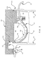
- housing 26 includes mechanical receptacle 66 for receiving and supporting the infusate container 34 as the infusate is drawn out of the container 34.
- the receptacle 66 may be a particular size capable of receiving a particularly sized infusate container 34 or it may be structured so as to receive containers of variable sizes.
- FIG.5 also shows an embodiment of an infusate container removal lockout mechanism 68 that is provided with the housing 26 to prevent the removal of container 34 while the pumping mechanism 56 (shown in FIG. 3) is running.
- mechanism 68 slides out of housing 26 and mechanically prevents removal of the infusate container 34 from the cassette 10.
- Mechanism 68 may be in communication with the infusion system electronic controller 42, which will only signal the pumping mechanism 56 that it may run when the lockout mechanism 68 is in a locked position.
- the infusate container 34 may be physically removed from the cassette 10 and the electronic controller 42 will signal the pumping mechanism 56 to halt the infusate flow.
- the electronic controller 42 will again signal the pumping mechanism 56 that it may run. If the electrical power system 44 (shown in FIG. 2) or software to controller 42 fails, mechanism 68 can be manually pushed back into housing 26 to allow removal of container 34. This feature of the present invention may remove the need for a purging sequence each time an infusate container 34 is removed and replaced by another container containing an infusate with the same identity and concentration as the infusate of the prior container.
- FIG. 6b shows an alternative embodiment of cassette 10 in which spike 12 is attached to delivery conduit 27 and can be removed from cassette 10 so that the cassette itself might be reusable with a new spike assembly 98.
- Spike assembly 98 fits into conduit 27, which fits into slot 96 of the cassette 10.
- housing 26 helps to keep spike set 98 securely held within slot 96.
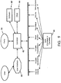
- FIG. 7 illustrates various mechanisms for tracking the volume of infusate pumped out of the infusate container 34 during the infusion process.
- Methods for volume tracking provide redundancy to the volume calculated by the infusion system electronic controller 42 from the cycles of the pumping mechanism and the duration of the infusion so that the accuracy of the pumping mechanism's 56 flow rate may be verified and compensated for. This redundancy helps ensures a dependable and accurate flow rate of infusate into the patient.
- Another volume tracking mechanism is the photo emitter/detector array 70 for meniscus tracking described above with reference to FIG. 5.
- Further volume tracking may be provided by tracking internal encoder counts 94 and 96 of the pumping mechanism 56. Because most pumps use a motor to drive the pumping mechanism, there is typically a set volume of infusate delivered with each revolution or cycle of the pump's motor. If an encoder mechanism, such as a set of optical emitter/detector cells capable of detecting the passage of slots in the pump's cam, is provided with the pump, each revolution of the pump's motor can be detected. The electronic controller 42 can multiply the number of revolutions per minute of the pump's motor by the volume of infusate delivered per revolution to derive the infusion rate in volume per minute. The controller 42 can then integrate flow rate over time to calculate the total volume infused over time and derive average flow rate too.
- an encoder mechanism such as a set of optical emitter/detector cells capable of detecting the passage of slots in the pump's cam
- FIG. 8 shows various optional methods for alerting the electronic controller 42 of reason to shut off the pumping mechanism 56. These methods help to prevent air from being pumped into a patient's blood circulation and help to prevent an incorrect (e.g., expired, previously used, or unrecognized) infusate or an incorrect dose from being administered to a patient.
- an incorrect e.g., expired, previously used, or unrecognized
- the user manually signals for a pump shut down if air is observed traveling towards the patient.
- the user interacts with a user interface 32 (shown in FIG. 1) which is in communication with the electronic controller 42.
- An air-in-line detector 90 may also be provided within the infusion system 36 to sense air bubbles within the infusate.
- the air-in-line detector 90 is in communication with the electronic controller 42.
- the electronic controller 42 may be programmed to send a signal to the pumping mechanism 56 to terminate the flow rate upon notice of a signal from the air-in-line detector 90.
- the conduit or PVC tubing 27 may then be purged of air.
- At least one occlusion detector 91 is provided with the cassette 10 or with the infusion system 36 to sense via associated pressure changes whether a kink or obstruction to flow is present in the delivery conduit 27.
- the occlusion detector 91 is in communication with the electronic controller 42 and sends a signal to the controller 42 when such an obstruction is detected.
- the controller 42 may be programmed to send a signal to the pumping mechanism 56 to terminate the flow rate upon notice of a signal from the occlusion detector 91.
- an air-entrainment lockout mechanism 93 is provided with the cassette 10 or with the infusion system 36.
- An air-entrainment lockout mechanism 93 is triggered by the removal of an infusate container 34 from the cassette 10 while the pumping mechanism 56 is running. Once triggered, the air-entrainment lockout mechanism 93 halts the flow of infusate within the cassette 10.
- An example of an air-entrainment lockout mechanism 93 is a micro-switch located on or near the infusate flow activation device 12.
- the micro-switch may be a spring-loaded button that is depressed as long as the infusate container 34 is on the activation device 12 and is released when the container 34 is removed, it may be a spring-loaded button positioned in such a location as to be depressed by the surface of the infusate container 34 as the container is removed, or it may be an electronic sensor such as an optical, electromagnetic, inductive or capacitive sensor that registers when the infusate container 34 is removed.
- a cassette removal lockout mechanism 95 may be provided with the infusion system 36 to prevent the removal of the cassette 10 while the pumping mechanism 56 is running.
- the mechanism 95 When in a locked position, the mechanism 95 mechanically fastens the cassette 10 to housing 26.
- the mechanism 95 may be in communication with the electronic controller 42, which will only signal the pumping mechanism 56 that it may run when the lockout mechanism 95 is in a locked position.
- the cassette 10 When in an unlocked position, the cassette 10 may be physically removed from the housing 26 and the electronic controller 42 will signal the pumping mechanism 56 to halt the infusate flow. Once a new cassette 10 is fitted within the housing 26 and the lockout mechanism 95 is returned to a locked position, the electronic controller 42 will again signal the pumping mechanism 56 that it may run.
- the mechanical cassette lockout mechanism 95 may be readily implemented by manually operated or motorized brackets, locks, twist locks, cams, levers, or any mechanical part that, when extended, physically prevents removal of the cassette. Sensors such as, among others, microswitches, proximity sensors, capacitive, magnetic, Hall effect, optical and inductive sensors may monitor the position of the manually operated or motorized cassette lockout mechanisms 95 and may communicate this data to controller 42.
- the cassette lockout functionality may also be implemented via software (which can be run on electronic controller 42) whereby the software receives a request or indication of a request to allow removal of the cassette 10, then checks the prevailing conditions (e.g., among others, whether infusate is being infused, whether an end of case has been signaled, whether the cassette 10 has been flagged as non-QAM compliant), and then allows the cassette 10 to be removed (manually or automatically) if it is safe to do so.
- the cassette 10 may only be removed via a request to the control software.
- the software may control a motorized lockout mechanism 95 that can not be manually activated in normal operation.
- the user is allowed to override the software and remove the cassette 10 after at least one warning message that the user has to acknowledge.
- Different ways to combine mechanical and software cassette lockout features into hybrid designs will be known to one skilled in the art.
- various QAMs 35 which can be attached to the cassettes 10 and containers 34 are contemplated which store information to be communicated to the electronic controller 42. If a parameter recorded on a QAM 35 is out of a preprogrammed range stored in memory by the electronic controller 42, then the controller 42 may send a signal to the pumping mechanism 56 to terminate or not initiate infusion.
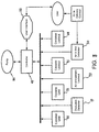
- FIG. 9 is a block diagram of certain parameters that the infusate container QAM 35 and cassette QAM 35 may store.
- Tags on the infusate container 34 or cassette 10 may store such parameters as the identity, concentration, initial volume or meniscus height of an infusate, characteristic dimensions or volumes of infusate containers, container identification, internal volume of the infusion set and cassette 10, density of the infusate, serial number, batch number, expiration date, address such as a Universal Resource Locator (URL) and manufacturer identification in a barcode or RFID integrated circuit for example. Examples of such tags and QAMs and their uses with integrated infusion systems are described in U.S. Patent Application No. 10/151,255 filed May 21, 2002 and Application No. 60/324,043 filed September 24, 2001 .
- the electronic controller 42 receives the parameter data from the QAMs 35 and processes it to determine the initial conditions of the infusion setup.
- the controller 42 may use infusate identity data encoded on a QAM 35 to authenticate product source and quality and ensure that the particular infusate to be infused is the infusate intended for the current patient.
- inadvertent administration of infusate contra-indicated for the patient may be flagged and averted.
- the electronic controller 42 uses data from the QAMs 35 to coordinate an automated purging or priming sequence.
- a QAM 35 on the cassette 10 may store the internal volume between the infusate container 34 and vascular access device such as, among others, the internal volume of the infusate flow lumens in the cassette 10, delivery conduit 27 and IV manifold 72 (FIG. 10).
- the electronic controller 42 records these internal volumes or their sum from the QAMs 35 and signals the pumping mechanism 56 to cause a volume of infusate in excess of the sum of the internal volumes to flow through the infusion set to clear any air or prior infusate remaining in the lines.
- the electronic controller 42 references a clock 90 (FIG. 9) to establish the start time and duration of each infusion run.
- the controller 42 may also use the clock 90 to determine when pre-programmed events such as pump flow rate or infusate container changes should occur.
- the controller 42 may also use the clock 90 and the infusion rate over a given time period to determine how much infusate is left in the container 34 so as to shut off the pump 56 when the volume of infusate remaining in the container 34 is low and alert the user.
- FIG. 10 shows an anti-reflux valve 77 on connector 72 connecting delivery conduit 27 with tubing 80 from the IV solution, or other fluid, container 78 and vascular access device 84.
- Anti-reflux valve 77 prevents the retrograde flow of infusate from tubing 27 into IV tubing 80.
- Check valve 76 can also operate as an automated free flow prevention device by deliberately increasing its cracking or opening pressure such that it is higher than the highest hydrostatic pressure generated by a spiked and full infusate container 34 with conduit 27 fully extended to its highest possible elevation. The design thus requires pumping mechanism 56 to generate more pressure than the opening pressure of valve 76 for infusate to flow to the patient. If the pump mechanism 56 (shown in FIG. 3) is not in contact with conduit 27 and pressure plate 20, when cassette 10 is removed from housing 26 or infusion system 36 for example, infusate flow will stop because the highest hydrostatic head that can be generated will be lower than the cracking pressure of valve 76.
- FIG. 11 shows a block diagram of an embodiment of the present invention and depicts the infusate and atmospheric air flow pathways through the elements of FIGS. 3 and 10 described above.
- Pinch valve 82 is open when the cassette 10 is snapped onto housing 26 or infusion system 36. As soon as cassette 10 is snapped off, the spring in pinch valve 82 extends and closes off IV line 27. The purpose of pinch valve 82 is to prevent free flow of infusate by gravity to the patient, when flow through conduit 27 is no longer being controlled by pumping mechanism 56 because conduit 27 is no longer in contact with it.
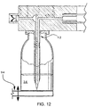
- FIG. 12 shows an alternative embodiment in which infusate flow activation device 12 allows transfer of infusate from an upright infusate container.
- An elevator 94 is used to raise upright infusate container 34 into communication with the activation device 12.
- an inverted spike is used as the activation device 12. If the infusate container 34 is placed upright as in FIG. 12, the possibility of the liquid contents flowing out by gravity via an air venting lumen is eliminated.
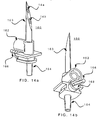
- FIG. 14a is a perspective view of an embodiment of a spike assembly 160 which may be fitted to cassette 150 and to peristaltic tubing at connector 164.
- Spike assembly 160 includes spike 163 and may include any or all of air filter housing 162, tapered outlet connector 164 for connection to peristaltic tubing (or other infusion conduit) and lever arm 166 or other like means for actuating a stopcock 168 (FIG. 14b).
- Spike 163 may include lumens 14a (air venting lumen) and 14b (infusate flow lumen). Air flows via lumen 14a into an infusate container when placed over spike assembly 160 and spiked. This air flow may prevent vacuum buildup inside an infusate container when the container contents are emptied during infusion.
- Air filter housing 162 may house a filter element (not shown) that filters out airborne disease organisms from the ambient air that flows into the infusate container via lumen 14a. Air filter housing 162 may be designed so as to eliminate the use of an air filter media holder that is traditionally used to contain the air filter media, further reducing parts count and cost of manufacture for the apparatus of the present invention.
- a closed infusate lumen 14b prevents free flow of residual infusate left in peristaltic and intravenous set tubing and prevents potential entrainment of air emboli into the patient's bloodstream in situations where a used cassette 150 is removed from mating surface 200 while the intravenous set tubing is still connected to a patient.
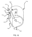
- FIG. 16 shows a perspective view of spike sheath 158 which may include portion 190, opening 188 to let spike 163 go through spike sheath 158 and protuberances 182 and 186 that engage with lever arm 166 (FIG. 14b) to close and open stopcock 168 respectively as spike sheath 158 travels up and down (FIGs. 17a and 17b).
- a step 180 may be provided with a lip 191 which engages with an infusate container holder (not shown).
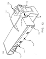
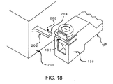
- FIG. 18 shows part of cassette body 156 oriented for engagement with mating surface 200 but not yet contacting the surface.
- Peg 202 includes edge 204 that slides along groove 192 (FIG. 16) on cassette body 156 and on portion 190 (FIG. 16) of spike sheath 158.
- Peg 202 may also include a protuberance 206 that abuts against end 174 (FIG. 15) to deploy movable member 172 when cassette 150 is fully engaged with mating surface 200.
- Protuberance 206 travels along groove 192.
- a cutout behind protuberance 206 on peg 202 may be included to allow spike sheath 158 to travel downwards without catching on peg 202.
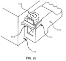
- FIG. 19 shows part of cassette body 156 partially engaged with mating surface 200.
- Edge 204 of protuberance 206 (FIG. 18) of peg 202 is shown engaged in groove 192 on portion 190 (FIG. 16).
- Spike sheath 158 is still prevented by movable member 172 (FIG. 15) from moving downwards and exposing spike 163.
- the infusate container holder (not shown) is engaging step 180 and lip 191 of the spike sheath (FIG. 16).
- a cassette 150 may be provided as part of a kit of disposable elements for use with an infusate container infusion system such as that described in U.S. Patent Application No. 09/324,759, filed June 3, 1999 .
- the cassette may also be provided alone as a disposable or reusable component of an infusate container infusion system.
- the cassette 150 of the present invention may be unpacked from a kit or other packaging or storing material with spike sheath 158 in an up or deployed position so that spike 163 is not exposed.
- Cassette 150 may be secured to mating surface 200 by an automated mechanism (not shown) or manually.
- a first infusate container may be unspiked as described above while leaving cassette 150 secured to mating surface 200. Closed infusate lumen 14b prevents aspiration of air into the peristaltic and IV tubing such that there is no need to purge or prime the IV and/or peristaltic tubing again after changing infusate containers. A new infusate container may then be loaded in the infusate container holder and spiked as described above.
Claims (7)
- Dispositif de soins (36) servant à administrer une sédation à un patient ayant besoin d'être sédaté, ledit dispositif comprenant :une tubulure de médicaments (27) qui achemine un flux de médicaments d'un récipient de perfusion (34) à un patient ;une pompe à perfusion (56) provoquant le flux de médicaments à travers la tubulure de médicaments ;un dispositif de commande de l'administration de médicaments raccordé à la pompe à perfusion pour administrer un taux de dose de sédatif audit patient au cours de ladite procédure ;une cassette (10) adaptée pour porter le récipient de perfusion est raccordée de façon amovible à un boîtier (26) du dispositif (36), dans lequel une partie de la tubulure de médicaments est placée de façon adjacente à la cassette, de sorte que la pompe à perfusion fonctionne en coopération avec un dispositif d'activation du flux (12) afin de déclencher le transfert du médicament du récipient de perfusion (34) à la tubulure de médicaments (27) et générer le taux de dose de sédatif ;caractérisé en ce que le boîtier (26) du dispositif comprend en outre un réservoir mécanique (66) permettant de recevoir et de supporter le récipient de perfusion (34) et un mécanisme (68) servant à empêcher le retrait dudit récipient de perfusion pendant que ledit dispositif de commande de l'administration de médicaments est en train d'administrer ledit taux de dose de sédatif.
- Dispositif de soins selon la revendication 1, comprenant en outre un moniteur de soins adapté pour être couplé audit patient et pour générer un signal indiquant des mesures d'un état physiologique du patient.
- Dispositif de soins selon la revendication 1 ou 2, comprenant en outre un mécanisme de saisie manuelle permettant au personnel effectuant la procédure de modifier manuellement l'administration du sédatif.
- Dispositif de soins selon la revendication 1, dans lequel ledit récipient de perfusion est une fiole.
- Dispositif de soins selon l'une quelconque des revendications 1 à 4, dans lequel un élévateur (94) soulève de façon verticale ledit récipient de perfusion (34) pour être en communication avec le dispositif d'activation (12).
- Dispositif de soins selon l'une quelconque des revendications 1 à 5, comprenant en outre un appareil de suivi du volume pour suivre le volume de sédatif dans le récipient de perfusion.
- Dispositif de soins selon l'une quelconque des revendications 1 à 6, dans lequel ladite cassette comprend en outre un module d'assurance qualité (MAQ) (35) qui stocke des informations à communiquer au dispositif de commande électronique, et dans lequel ledit dispositif comprend en outre un mécanisme servant à lire des informations sur le MAQ et à communiquer ces informations au dispositif de commande électronique.
Applications Claiming Priority (5)
| Application Number | Priority Date | Filing Date | Title |
|---|---|---|---|
| US30859201P | 2001-07-31 | 2001-07-31 | |
| US308592P | 2001-07-31 | ||
| US37804602P | 2002-05-16 | 2002-05-16 | |
| US378046P | 2002-05-16 | ||
| PCT/US2002/024055 WO2003011377A1 (fr) | 2001-07-31 | 2002-07-31 | Dispositifs et procedes servant a administrer une perfusion intraveineuse |
Publications (2)
| Publication Number | Publication Date |
|---|---|
| EP1412003A1 EP1412003A1 (fr) | 2004-04-28 |
| EP1412003B1 true EP1412003B1 (fr) | 2007-11-14 |
Family
ID=26976321
Family Applications (1)
| Application Number | Title | Priority Date | Filing Date |
|---|---|---|---|
| EP02756778A Expired - Lifetime EP1412003B1 (fr) | 2001-07-31 | 2002-07-31 | Dispositifs servant a administrer une perfusion intraveineuse |
Country Status (12)
| Country | Link |
|---|---|
| US (1) | US20030040700A1 (fr) |
| EP (1) | EP1412003B1 (fr) |
| JP (2) | JP4488339B2 (fr) |
| CN (1) | CN1285388C (fr) |
| AT (1) | ATE378080T1 (fr) |
| AU (1) | AU2002322763B2 (fr) |
| CA (1) | CA2455982C (fr) |
| DE (1) | DE60223549T2 (fr) |
| ES (1) | ES2296981T3 (fr) |
| HK (1) | HK1064967A1 (fr) |
| MX (1) | MXPA04001065A (fr) |
| WO (1) | WO2003011377A1 (fr) |
Families Citing this family (134)
| Publication number | Priority date | Publication date | Assignee | Title |
|---|---|---|---|---|
| US7503461B1 (en) * | 2002-05-13 | 2009-03-17 | The United States Of America As Represented By The Secretary Of The Air Force | Air-admittance device and method for making same |
| MXPA04011395A (es) | 2002-05-16 | 2005-02-17 | Scott Lab Inc | Mecanismos de introduccion a recipiente de farmaco y metodo. |
| JP3925858B2 (ja) * | 2002-11-08 | 2007-06-06 | 日本精密測器株式会社 | 非観血式血圧計 |
| IL152865A0 (en) * | 2002-11-14 | 2003-06-24 | Q Core Ltd | Peristalic pump |
| US8075514B2 (en) * | 2003-03-28 | 2011-12-13 | Carefusion 303, Inc. | Infusion data communication system |
| WO2004110524A2 (fr) * | 2003-06-06 | 2004-12-23 | Phacor, Inc. | Cassette d'ecoulement de fluide pour instrument de chirurgie ophtalmique |
| US20050108057A1 (en) * | 2003-09-24 | 2005-05-19 | Michal Cohen | Medical device management system including a clinical system interface |
| WO2005084732A1 (fr) | 2004-03-03 | 2005-09-15 | Nemoto Kyorindo Co., Ltd. | Systeme d'injection de solution medicale |
| US20050277873A1 (en) * | 2004-05-27 | 2005-12-15 | Janice Stewart | Identification information recognition system for a medical device |
| US7927313B2 (en) * | 2004-05-27 | 2011-04-19 | Baxter International Inc. | Medical device configuration based on recognition of identification information |
| KR101237767B1 (ko) | 2004-08-31 | 2013-02-28 | 에디컨 엔도-서저리 인코포레이티드 | 의료용 이펙터 시스템 |
| US20060042634A1 (en) * | 2004-08-31 | 2006-03-02 | Nalagatla Anil K | Device for connecting a cannula to a medical effector system |
| AU2012201650B2 (en) * | 2004-08-31 | 2013-01-31 | Ethicon Endo-Surgery, Inc. | Medical effector system |
| US8308457B2 (en) * | 2004-11-24 | 2012-11-13 | Q-Core Medical Ltd. | Peristaltic infusion pump with locking mechanism |
| IL165365A0 (en) | 2004-11-24 | 2006-01-15 | Q Core Ltd | Finger-type peristaltic pump |
| US7568619B2 (en) * | 2004-12-15 | 2009-08-04 | Alcon, Inc. | System and method for identifying and controlling ophthalmic surgical devices and components |
| EP1853333A1 (fr) * | 2004-12-23 | 2007-11-14 | Bracco Research S.A. | Dispositif de transfert de liquide pour recipients d'administration medicaux |
| US20060206028A1 (en) * | 2005-03-11 | 2006-09-14 | Qi Yu | Apparatus and method for ablating deposits from blood vessel |
| CN101185607A (zh) * | 2005-04-06 | 2008-05-28 | 马林克罗特公司 | 管理有关医用液体及其容器的信息的系统与方法 |
| US20070025869A1 (en) * | 2005-07-15 | 2007-02-01 | Gordon John H | Fluid Delivery Device |
| US20070060874A1 (en) * | 2005-09-12 | 2007-03-15 | Nesbitt Matthew T | Apparatus and methods for controlling and automating fluid infusion activities |
| WO2007035564A2 (fr) * | 2005-09-19 | 2007-03-29 | Lifescan, Inc. | Detection de fonctionnement defectueux a calcul de derive |
| US20070066940A1 (en) * | 2005-09-19 | 2007-03-22 | Lifescan, Inc. | Systems and Methods for Detecting a Partition Position in an Infusion Pump |
| WO2007035567A2 (fr) * | 2005-09-19 | 2007-03-29 | Lifescan, Inc. | Pompe de perfusion avec commande en circuit fermé et algorithme |
| WO2008018889A2 (fr) | 2005-09-29 | 2008-02-14 | The General Hospital Corporation | Procédés et appareil pour la simulation autonome d'un accident |
| EP1776977A1 (fr) * | 2005-10-21 | 2007-04-25 | General Electric Company | Système pour délivrer des médicaments anesthésiants à un patient |
| JP4980927B2 (ja) * | 2005-11-25 | 2012-07-18 | 株式会社根本杏林堂 | 薬液連結装置および薬液注入装置 |
| US8762172B2 (en) * | 2006-06-29 | 2014-06-24 | The Invention Science Fund I, Llc | Verification technique for patient diagnosis and treatment |
| US8719054B2 (en) * | 2006-06-29 | 2014-05-06 | The Invention Science Fund I, Llc | Enhanced communication link for patient diagnosis and treatment |
| US8417547B2 (en) * | 2006-06-29 | 2013-04-09 | The Invention Science Fund I, Llc | Verification technique for patient diagnosis and treatment |
| US20080059246A1 (en) * | 2006-06-29 | 2008-03-06 | Searete Llc, A Limited Liability Corporation Of State Of Delaware | Verification technique for patient diagnosis and treatment |
| US8165896B2 (en) * | 2006-06-29 | 2012-04-24 | The Invention Science Fund I, Llc | Compliance data for health-related procedures |
| US8468031B2 (en) * | 2006-06-29 | 2013-06-18 | The Invention Science Fund I, Llc | Generating output data based on patient monitoring |
| US20080208635A1 (en) * | 2006-06-29 | 2008-08-28 | Searete Llc, | Data maintenance via patient monitoring technique |
| US8140353B2 (en) * | 2006-06-29 | 2012-03-20 | The Invention Science Fund I, Llc | Compliance data for health-related procedures |
| US8326645B2 (en) * | 2006-06-29 | 2012-12-04 | The Invention Science Fund I, Llc | Verification technique for patient diagnosis and treatment |
| US20080004903A1 (en) * | 2006-06-29 | 2008-01-03 | Searete Llc, A Limited Liability Corporation Of The State Of Delaware | Enhanced communication link for patient diagnosis and treatment |
| US7991628B2 (en) * | 2006-06-29 | 2011-08-02 | The Invention Science Fund I, Llc | Generating output data based on patient monitoring |
| US8135596B2 (en) * | 2006-06-29 | 2012-03-13 | The Invention Science Fund I, Llc | Generating output data based on patient monitoring |
| US8417546B2 (en) * | 2006-06-29 | 2013-04-09 | The Invention Science Fund I, Llc | Verification technique for patient diagnosis and treatment |
| US20080000995A1 (en) * | 2006-06-29 | 2008-01-03 | Searete Llc, A Limited Liability Corporation Of The State Of Delaware | Enhanced communication link for patient diagnosis and treatment |
| US20080077447A1 (en) * | 2006-06-29 | 2008-03-27 | Searete Llc, A Limited Liability Corporation Of The State Of Delaware | Enhanced communication link for patient diagnosis and treatment |
| IL179231A0 (en) | 2006-11-13 | 2007-03-08 | Q Core Ltd | A finger-type peristaltic pump comprising a ribbed anvil |
| US8535025B2 (en) | 2006-11-13 | 2013-09-17 | Q-Core Medical Ltd. | Magnetically balanced finger-type peristaltic pump |
| IL179234A0 (en) | 2006-11-13 | 2007-03-08 | Q Core Ltd | An anti-free flow mechanism |
| US7935086B2 (en) * | 2006-12-14 | 2011-05-03 | L M M Global Innovations, Inc. | Multiple drug injection apparatus |
| US7654127B2 (en) * | 2006-12-21 | 2010-02-02 | Lifescan, Inc. | Malfunction detection in infusion pumps |
| US8568391B2 (en) * | 2007-04-20 | 2013-10-29 | Doheny Eye Institute | Sterile surgical tray |
| US8496609B2 (en) * | 2007-07-05 | 2013-07-30 | Baxter International Inc. | Fluid delivery system with spiked cassette |
| WO2009011103A1 (fr) * | 2007-07-17 | 2009-01-22 | Nemoto Kyorindo Co., Ltd. | Dispositif de perfusion de fluide médical, appareil de saisie d'images fluoroscopiques et programme d'ordinateur |
| US8062008B2 (en) | 2007-09-27 | 2011-11-22 | Curlin Medical Inc. | Peristaltic pump and removable cassette therefor |
| US7934912B2 (en) | 2007-09-27 | 2011-05-03 | Curlin Medical Inc | Peristaltic pump assembly with cassette and mounting pin arrangement |
| US8083503B2 (en) | 2007-09-27 | 2011-12-27 | Curlin Medical Inc. | Peristaltic pump assembly and regulator therefor |
| US8226606B2 (en) | 2007-09-28 | 2012-07-24 | Calibra Medical, Inc. | Disposable infusion device with tactile dosage volume indicator |
| WO2009086182A1 (fr) * | 2007-12-21 | 2009-07-09 | Carticept Medical, Inc. | Système d'injection articulaire |
| US9044542B2 (en) | 2007-12-21 | 2015-06-02 | Carticept Medical, Inc. | Imaging-guided anesthesia injection systems and methods |
| US8545440B2 (en) | 2007-12-21 | 2013-10-01 | Carticept Medical, Inc. | Injection system for delivering multiple fluids within the anatomy |
| US8425470B2 (en) * | 2008-04-01 | 2013-04-23 | Zevex, Inc. | Anti-free-flow mechanism for enteral feeding pumps |
| EP2277126A2 (fr) * | 2008-04-02 | 2011-01-26 | Pro-Iv Ltd. | Robinet compte-gouttes à verrouillage |
| JP5726070B2 (ja) | 2008-06-06 | 2015-05-27 | バイエル メディカル ケア インコーポレーテッド | 流体注入ボーラスの患者へ送達及び有害流体を取り扱う装置及び方法 |
| US20100022987A1 (en) * | 2008-07-24 | 2010-01-28 | Walter John Bochenko | Medication delivery system |
| US20100204659A1 (en) * | 2008-07-24 | 2010-08-12 | The Regents Of The University Of California | Medication delivery system |
| EP2376146A2 (fr) * | 2008-10-31 | 2011-10-19 | Mallinckrodt LLC | Système d injection de doses multiples |
| EP2198778B1 (fr) * | 2008-12-19 | 2013-07-03 | F. Hoffmann-La Roche AG | Dispositif de perfuseur avec mesure d'impédance |
| US20100217233A1 (en) * | 2009-02-20 | 2010-08-26 | Ranft Elizabeth A | Method and device to anesthetize an area |
| TWI394516B (zh) * | 2009-04-16 | 2013-04-21 | Htc Corp | 可攜式電子裝置 |
| US9480789B2 (en) | 2009-06-01 | 2016-11-01 | Ethicon Endo-Surgery, Inc. | Method and sedation delivery system including a pump assembly and a co-formulation of first and second drugs |
| WO2010149187A1 (fr) | 2009-06-25 | 2010-12-29 | Nestec S.A. | Ensemble de pince pour cassette d'infusion |
| US8777897B2 (en) * | 2009-07-06 | 2014-07-15 | Carefusion 303, Inc. | Fluid delivery systems and methods having wireless communication |
| IN2012DN00396A (fr) * | 2009-07-13 | 2015-05-22 | Nestec Sa | |
| US9242042B2 (en) * | 2009-07-21 | 2016-01-26 | Ethicon Endo-Surgery, Inc. | Drug delivery system including a drug-container holder and a pump assembly |
| DE102009051945A1 (de) * | 2009-11-04 | 2011-05-05 | Fresenius Medical Care Deutschland Gmbh | Medikamentenapplikationsadapter mit Gassperrelement für ein Hämodialyseschlauchset |
| IT1397622B1 (it) | 2009-12-15 | 2013-01-18 | Gambro Lundia Ab | Elemento di tenuta per dispositivi per clampare tubi flessibili in macchine medicali |
| US8371832B2 (en) | 2009-12-22 | 2013-02-12 | Q-Core Medical Ltd. | Peristaltic pump with linear flow control |
| US8142400B2 (en) * | 2009-12-22 | 2012-03-27 | Q-Core Medical Ltd. | Peristaltic pump with bi-directional pressure sensor |
| US8197438B2 (en) * | 2009-12-23 | 2012-06-12 | Roche Diagnostics Operations, Inc. | Medicinal fluid delivery systems and methods for priming the same |
| CA2786013C (fr) * | 2010-01-29 | 2018-08-07 | Kci Licensing, Inc. | Systemes et procedes de positionnement d'un systeme d'alimentation en fluide |
| EP2558147A4 (fr) | 2010-04-12 | 2014-12-17 | Q Core Medical Ltd | Piège à air pour la pompe intraveineuse |
| WO2012024106A2 (fr) | 2010-08-17 | 2012-02-23 | University Of Florida Research Foundation, Inc. | Photopléthysmographie de site central, administration de médicament et sécurité |
| US9498573B2 (en) | 2010-09-24 | 2016-11-22 | Perqflo, Llc | Infusion pumps |
| US8777901B2 (en) | 2010-09-24 | 2014-07-15 | Perqflo, Llc | Infusion pumps |
| US8915879B2 (en) | 2010-09-24 | 2014-12-23 | Perqflo, Llc | Infusion pumps |
| US9216249B2 (en) | 2010-09-24 | 2015-12-22 | Perqflo, Llc | Infusion pumps |
| US8905972B2 (en) | 2010-11-20 | 2014-12-09 | Perqflo, Llc | Infusion pumps |
| CN102028991A (zh) * | 2011-01-11 | 2011-04-27 | 毛爱民 | 使输液管两侧同时对应接受压力而回位的方法 |
| US9674811B2 (en) | 2011-01-16 | 2017-06-06 | Q-Core Medical Ltd. | Methods, apparatus and systems for medical device communication, control and localization |
| US9726167B2 (en) | 2011-06-27 | 2017-08-08 | Q-Core Medical Ltd. | Methods, circuits, devices, apparatuses, encasements and systems for identifying if a medical infusion system is decalibrated |
| JP5209765B2 (ja) | 2011-07-28 | 2013-06-12 | プライムテック株式会社 | 流体輸送駆動ユニット、および流体輸送駆動ユニットの制御プログラム |
| US9092559B2 (en) * | 2011-08-16 | 2015-07-28 | Ethicon Endo-Surgery, Inc. | Drug delivery system with open architectural framework |
| CA2875074A1 (fr) * | 2012-03-17 | 2013-09-26 | Abbott Medical Optics Inc. | Cassette chirurgicale |
| US9125976B2 (en) | 2012-06-07 | 2015-09-08 | Bayer Medical Care Inc. | Shield adapters |
| US9889288B2 (en) | 2012-06-07 | 2018-02-13 | Bayer Healthcare Llc | Tubing connectors |
| US9039592B2 (en) * | 2012-06-07 | 2015-05-26 | Bayer Medical Care Inc. | Radiopharmaceutical delivery device |
| US9393441B2 (en) | 2012-06-07 | 2016-07-19 | Bayer Healthcare Llc | Radiopharmaceutical delivery and tube management system |
| US10602740B2 (en) * | 2012-07-10 | 2020-03-31 | Lifeline Scientific, Inc. | Organ perfusion apparatus with downstream flow control |
| US9468715B2 (en) * | 2012-09-17 | 2016-10-18 | Micrel Medical Devices S.A. | Infusion rotary peristaltic pump |
| JP6205701B2 (ja) * | 2012-10-22 | 2017-10-04 | セイコーエプソン株式会社 | 流体注入装置 |
| WO2014082003A1 (fr) | 2012-11-26 | 2014-05-30 | Kci Licensing, Inc. | Pompe et système de stockage de solution combinés pour utilisation avec un système de traitement à pression réduite |
| WO2014123846A1 (fr) | 2013-02-05 | 2014-08-14 | Fluidnet Corporation | Gestion d'un dispositif médical au moyen d'associations |
| US9855110B2 (en) | 2013-02-05 | 2018-01-02 | Q-Core Medical Ltd. | Methods, apparatus and systems for operating a medical device including an accelerometer |
| EP2954484A4 (fr) * | 2013-02-05 | 2016-02-17 | Ivenix Inc | Programmation automatisée de thérapie par perfusion |
| US9433728B2 (en) | 2013-03-01 | 2016-09-06 | Bayer Healthcare Llc | Valveless pharmaceutical infusion system |
| US9597439B2 (en) | 2013-03-15 | 2017-03-21 | Fresenius Medical Care Holdings, Inc. | Medical fluid sensing and concentration determination using radio frequency energy and a magnetic field |
| US9713664B2 (en) | 2013-03-15 | 2017-07-25 | Fresenius Medical Care Holdings, Inc. | Nuclear magnetic resonance module for a dialysis machine |
| US9433718B2 (en) | 2013-03-15 | 2016-09-06 | Fresenius Medical Care Holdings, Inc. | Medical fluid system including radio frequency (RF) device within a magnetic assembly, and fluid cartridge body with one of multiple passageways disposed within the RF device, and specially configured cartridge gap accepting a portion of said RF device |
| US9772386B2 (en) | 2013-03-15 | 2017-09-26 | Fresenius Medical Care Holdings, Inc. | Dialysis system with sample concentration determination device using magnet and radio frequency coil assemblies |
| US9566377B2 (en) | 2013-03-15 | 2017-02-14 | Fresenius Medical Care Holdings, Inc. | Medical fluid sensing and concentration determination in a fluid cartridge with multiple passageways, using a radio frequency device situated within a magnetic field |
| EP3884859A1 (fr) * | 2013-06-27 | 2021-09-29 | Potrero Medical, Inc. | Sonde de foley pour détection |
| WO2015050752A1 (fr) * | 2013-10-01 | 2015-04-09 | Baxter International Inc. | Système de pompe à cartouche amovible |
| US10058652B2 (en) * | 2013-10-17 | 2018-08-28 | Micrel Medical Devices S.A. | Infusion pump device |
| US10286135B2 (en) | 2014-03-28 | 2019-05-14 | Fresenius Medical Care Holdings, Inc. | Measuring conductivity of a medical fluid |
| JP5863871B2 (ja) * | 2014-04-15 | 2016-02-17 | 日機装株式会社 | 装着部材及びしごき型ポンプ |
| US10159786B2 (en) | 2014-09-30 | 2018-12-25 | Perqflo, Llc | Hybrid ambulatory infusion pumps |
| EP3258989B1 (fr) | 2015-02-18 | 2020-01-01 | Medtronic Minimed, Inc. | Pompe à perfusion ambulatoire et ensembles réservoirs à utiliser avec celle-ci |
| EP3307349A4 (fr) * | 2015-06-15 | 2019-03-27 | Enspero Inc. | Dispositif de distribution à orifices multiples |
| WO2016208705A1 (fr) | 2015-06-24 | 2016-12-29 | 日機装株式会社 | Dispositif de purification du sang |
| CN112999464B (zh) * | 2015-08-28 | 2023-04-18 | 拜耳医药保健有限公司 | 针筒流体填充验证以及动力注射器系统特征的图像识别的系统和方法 |
| WO2017086879A1 (fr) * | 2015-11-18 | 2017-05-26 | Singapore Health Services Pte Ltd | Appareil et système d'administration de médicament, procédés de formation et de fonctionnement de ceux-ci |
| WO2017114910A1 (fr) * | 2015-12-30 | 2017-07-06 | Ascendis Pharma A/S | Auto-injecteur à mécanisme adaptable à air comprimé |
| CN108883230B (zh) | 2016-02-12 | 2022-10-04 | 美敦力米尼梅德有限公司 | 便携式输注泵及与其使用的组件 |
| US11065433B2 (en) | 2017-01-13 | 2021-07-20 | Joel S. Faden | Apparatus and methods of dispensing fluid intravenously and flushing lines of intravenous fluid administration systems |
| US9907946B1 (en) | 2017-01-13 | 2018-03-06 | Joel S. Faden | Apparatus and methods of dispensing fluid intravenously and flushing lines of intravenous fluid administration systems |
| US11058859B2 (en) | 2017-01-13 | 2021-07-13 | Joel S. Faden | Apparatus and methods of dispensing fluid intravenously and flushing lines of intravenous fluid administration systems |
| CN110177597B (zh) * | 2017-01-13 | 2022-05-17 | 乔尔·S·法登 | 静脉分配流体的设备和方法以及冲洗静脉流体施用系统的管线的设备和方法 |
| AU2018294519B2 (en) | 2017-06-29 | 2023-10-12 | Ascendis Pharma A/S | Auto injector with reconstitution handling support |
| CA3067839C (fr) * | 2017-07-07 | 2024-01-02 | Gojo Industries, Inc. | Distributeurs rechargeables a reservoirs et recipients de recharge concus pour un transfert de fluide et d'air entre ceux-ci |
| JP6464238B1 (ja) | 2017-09-07 | 2019-02-06 | 日機装株式会社 | 血液浄化装置及びその気泡の排出方法 |
| JP6462077B1 (ja) | 2017-09-07 | 2019-01-30 | 日機装株式会社 | 血液浄化装置及びその気泡の排出方法 |
| EP3689387A4 (fr) * | 2017-09-26 | 2021-08-11 | Nipro Corporation | Ensemble de tubes et pompe à tube comportant celui-ci |
| CN109602972B (zh) * | 2018-08-28 | 2022-01-25 | 英华达(上海)科技有限公司 | 输液装置 |
| WO2021011227A1 (fr) * | 2019-07-12 | 2021-01-21 | Baxalta GmbH | Système de perfusion |
| US11426515B2 (en) | 2019-07-25 | 2022-08-30 | Zevex, Inc. | Infusion pump cassette having integrated pinch clip occluder |
| ES2933693T3 (es) | 2019-11-18 | 2023-02-13 | Eitan Medical Ltd | Prueba rápida para bomba médica |
| CN115501115B (zh) * | 2022-11-08 | 2023-03-17 | 昌乐县人民医院 | 心内科喂药装置 |
Family Cites Families (19)
| Publication number | Priority date | Publication date | Assignee | Title |
|---|---|---|---|---|
| US6241704B1 (en) * | 1901-11-22 | 2001-06-05 | Sims Deltec, Inc. | Drug pump systems and methods |
| US5935099A (en) * | 1992-09-09 | 1999-08-10 | Sims Deltec, Inc. | Drug pump systems and methods |
| US4370983A (en) * | 1971-01-20 | 1983-02-01 | Lichtenstein Eric Stefan | Computer-control medical care system |
| US4551133A (en) * | 1984-04-16 | 1985-11-05 | American Hospital Supply Corporation | Patient controlled medication infusion system |
| DE3600496A1 (de) * | 1986-01-10 | 1987-07-16 | Josef Magasi | Punktionskanuele, deren griff sowie verfahren zu deren herstellung |
| US5645531A (en) * | 1993-05-26 | 1997-07-08 | Quest Medical, Inc. | Constant pressure blood mixture delivery system and method |
| US5827219A (en) * | 1993-10-28 | 1998-10-27 | Medrad, Inc. | Injection system and pumping system for use therein |
| US5431627A (en) * | 1993-11-12 | 1995-07-11 | Abbott Laboratories | Cassette identification system for use with a multi-program drug infusion pump |
| US5531697A (en) * | 1994-04-15 | 1996-07-02 | Sims Deltec, Inc. | Systems and methods for cassette identification for drug pumps |
| US5620312A (en) * | 1995-03-06 | 1997-04-15 | Sabratek Corporation | Infusion pump with dual-latching mechanism |
| US6165154A (en) | 1995-06-07 | 2000-12-26 | Deka Products Limited Partnership | Cassette for intravenous-line flow-control system |
| US6186977B1 (en) | 1997-04-24 | 2001-02-13 | Joseph L. Riley Anesthesia Associates | Apparatus and method for total intravenous anesthesia delivery and associated patient monitoring |
| ES2242289T3 (es) * | 1997-07-25 | 2005-11-01 | MINNESOTA INNOVATIVE TECHNOLOGIES & INSTRUMENTS CORPORATION (MITI) | Dispositivo de control para suministrar oxigeno suplementario para respiracion. |
| US6070761A (en) * | 1997-08-22 | 2000-06-06 | Deka Products Limited Partnership | Vial loading method and apparatus for intelligent admixture and delivery of intravenous drugs |
| DE69937558T2 (de) * | 1998-06-03 | 2008-03-06 | Scott Laboratories, Inc., Lubbock | Gerät zur linderung von schmerz bei bewusstsein und angstzuständen im zusammenhang mit medizinischen und chirurgischen eingriffen |
| AR021220A1 (es) * | 1998-09-15 | 2002-07-03 | Baxter Int | DISPOSITIVO DE CONEXIoN PARA ESTABLECER UNA COMUNICACIoN FLUíDA ENTRE UN PRIMER RECIPIENTE Y UN SEGUNDO RECIPIENTE. |
| US6202708B1 (en) | 1998-11-09 | 2001-03-20 | Sims Deltec, Inc. | Fillable cassette apparatus and method |
| US6231560B1 (en) * | 1999-02-10 | 2001-05-15 | Baxter International Inc | Method and apparatus for automatically controlling the level of medication |
| EP1189649B1 (fr) * | 1999-06-30 | 2005-06-15 | University Of Florida Research Foundation, Inc. | Systeme de commande de ventilateur |
-
2002
- 2002-07-31 CN CNB028193547A patent/CN1285388C/zh not_active Expired - Fee Related
- 2002-07-31 AU AU2002322763A patent/AU2002322763B2/en not_active Ceased
- 2002-07-31 EP EP02756778A patent/EP1412003B1/fr not_active Expired - Lifetime
- 2002-07-31 ES ES02756778T patent/ES2296981T3/es not_active Expired - Lifetime
- 2002-07-31 US US10/208,184 patent/US20030040700A1/en not_active Abandoned
- 2002-07-31 WO PCT/US2002/024055 patent/WO2003011377A1/fr active IP Right Grant
- 2002-07-31 DE DE60223549T patent/DE60223549T2/de not_active Expired - Lifetime
- 2002-07-31 JP JP2003516607A patent/JP4488339B2/ja not_active Expired - Fee Related
- 2002-07-31 CA CA002455982A patent/CA2455982C/fr not_active Expired - Fee Related
- 2002-07-31 AT AT02756778T patent/ATE378080T1/de not_active IP Right Cessation
- 2002-07-31 MX MXPA04001065A patent/MXPA04001065A/es active IP Right Grant
-
2004
- 2004-10-12 HK HK04107841A patent/HK1064967A1/xx not_active IP Right Cessation
-
2009
- 2009-07-22 JP JP2009171523A patent/JP2009279425A/ja not_active Withdrawn
Also Published As
| Publication number | Publication date |
|---|---|
| ES2296981T3 (es) | 2008-05-01 |
| CN1285388C (zh) | 2006-11-22 |
| JP4488339B2 (ja) | 2010-06-23 |
| MXPA04001065A (es) | 2004-05-20 |
| WO2003011377A1 (fr) | 2003-02-13 |
| ATE378080T1 (de) | 2007-11-15 |
| US20030040700A1 (en) | 2003-02-27 |
| HK1064967A1 (en) | 2005-02-08 |
| DE60223549D1 (de) | 2007-12-27 |
| JP2009279425A (ja) | 2009-12-03 |
| CN1561237A (zh) | 2005-01-05 |
| AU2002322763B2 (en) | 2007-08-09 |
| JP2005503202A (ja) | 2005-02-03 |
| DE60223549T2 (de) | 2008-09-25 |
| CA2455982C (fr) | 2008-03-25 |
| CA2455982A1 (fr) | 2003-02-13 |
| EP1412003A1 (fr) | 2004-04-28 |
Similar Documents
| Publication | Publication Date | Title |
|---|---|---|
| EP1412003B1 (fr) | Dispositifs servant a administrer une perfusion intraveineuse | |
| AU2002322763A1 (en) | Apparatuses and methods for providing IV infusion administration | |
| CA2485990C (fr) | Kits de fournitures medicales pour sedation et analgesie | |
| AU2019253887B2 (en) | Single-use disposable set connector | |
| US7150735B2 (en) | Drug container entry mechanisms and method | |
| US20070244437A1 (en) | Fluid delivery system with bulk container and pump assembly |
Legal Events
| Date | Code | Title | Description |
|---|---|---|---|
| PUAI | Public reference made under article 153(3) epc to a published international application that has entered the european phase |
Free format text: ORIGINAL CODE: 0009012 |
|
| 17P | Request for examination filed |
Effective date: 20040219 |
|
| AK | Designated contracting states |
Kind code of ref document: A1 Designated state(s): AT BE BG CH CY CZ DE DK EE ES FI FR GB GR IE IT LI LU MC NL PT SE SK TR |
|
| AX | Request for extension of the european patent |
Extension state: AL LT LV MK RO SI |
|
| 17Q | First examination report despatched |
Effective date: 20040601 |
|
| REG | Reference to a national code |
Ref country code: HK Ref legal event code: DE Ref document number: 1064967 Country of ref document: HK |
|
| RTI1 | Title (correction) |
Free format text: APPARATUS FOR PROVIDING IV INFUSION |
|
| GRAP | Despatch of communication of intention to grant a patent |
Free format text: ORIGINAL CODE: EPIDOSNIGR1 |
|
| GRAS | Grant fee paid |
Free format text: ORIGINAL CODE: EPIDOSNIGR3 |
|
| GRAA | (expected) grant |
Free format text: ORIGINAL CODE: 0009210 |
|
| AK | Designated contracting states |
Kind code of ref document: B1 Designated state(s): AT BE BG CH CY CZ DE DK EE ES FI FR GB GR IE IT LI LU MC NL PT SE SK TR |
|
| REG | Reference to a national code |
Ref country code: GB Ref legal event code: FG4D |
|
| REG | Reference to a national code |
Ref country code: CH Ref legal event code: EP |
|
| REG | Reference to a national code |
Ref country code: IE Ref legal event code: FG4D |
|
| REF | Corresponds to: |
Ref document number: 60223549 Country of ref document: DE Date of ref document: 20071227 Kind code of ref document: P |
|
| REG | Reference to a national code |
Ref country code: HK Ref legal event code: GR Ref document number: 1064967 Country of ref document: HK |
|
| PG25 | Lapsed in a contracting state [announced via postgrant information from national office to epo] |
Ref country code: LI Free format text: LAPSE BECAUSE OF FAILURE TO SUBMIT A TRANSLATION OF THE DESCRIPTION OR TO PAY THE FEE WITHIN THE PRESCRIBED TIME-LIMIT Effective date: 20071114 Ref country code: CH Free format text: LAPSE BECAUSE OF FAILURE TO SUBMIT A TRANSLATION OF THE DESCRIPTION OR TO PAY THE FEE WITHIN THE PRESCRIBED TIME-LIMIT Effective date: 20071114 Ref country code: SE Free format text: LAPSE BECAUSE OF FAILURE TO SUBMIT A TRANSLATION OF THE DESCRIPTION OR TO PAY THE FEE WITHIN THE PRESCRIBED TIME-LIMIT Effective date: 20080214 |
|
| REG | Reference to a national code |
Ref country code: ES Ref legal event code: FG2A Ref document number: 2296981 Country of ref document: ES Kind code of ref document: T3 |
|
| PG25 | Lapsed in a contracting state [announced via postgrant information from national office to epo] |
Ref country code: BG Free format text: LAPSE BECAUSE OF FAILURE TO SUBMIT A TRANSLATION OF THE DESCRIPTION OR TO PAY THE FEE WITHIN THE PRESCRIBED TIME-LIMIT Effective date: 20080214 Ref country code: FI Free format text: LAPSE BECAUSE OF FAILURE TO SUBMIT A TRANSLATION OF THE DESCRIPTION OR TO PAY THE FEE WITHIN THE PRESCRIBED TIME-LIMIT Effective date: 20071114 |
|
| REG | Reference to a national code |
Ref country code: CH Ref legal event code: PL |
|
| PG25 | Lapsed in a contracting state [announced via postgrant information from national office to epo] |
Ref country code: AT Free format text: LAPSE BECAUSE OF FAILURE TO SUBMIT A TRANSLATION OF THE DESCRIPTION OR TO PAY THE FEE WITHIN THE PRESCRIBED TIME-LIMIT Effective date: 20071114 |
|
| ET | Fr: translation filed | ||
| PG25 | Lapsed in a contracting state [announced via postgrant information from national office to epo] |
Ref country code: CZ Free format text: LAPSE BECAUSE OF FAILURE TO SUBMIT A TRANSLATION OF THE DESCRIPTION OR TO PAY THE FEE WITHIN THE PRESCRIBED TIME-LIMIT Effective date: 20071114 Ref country code: DK Free format text: LAPSE BECAUSE OF FAILURE TO SUBMIT A TRANSLATION OF THE DESCRIPTION OR TO PAY THE FEE WITHIN THE PRESCRIBED TIME-LIMIT Effective date: 20071114 |
|
| PG25 | Lapsed in a contracting state [announced via postgrant information from national office to epo] |
Ref country code: SK Free format text: LAPSE BECAUSE OF FAILURE TO SUBMIT A TRANSLATION OF THE DESCRIPTION OR TO PAY THE FEE WITHIN THE PRESCRIBED TIME-LIMIT Effective date: 20071114 Ref country code: BE Free format text: LAPSE BECAUSE OF FAILURE TO SUBMIT A TRANSLATION OF THE DESCRIPTION OR TO PAY THE FEE WITHIN THE PRESCRIBED TIME-LIMIT Effective date: 20071114 |
|
| PLBE | No opposition filed within time limit |
Free format text: ORIGINAL CODE: 0009261 |
|
| STAA | Information on the status of an ep patent application or granted ep patent |
Free format text: STATUS: NO OPPOSITION FILED WITHIN TIME LIMIT |
|
| PG25 | Lapsed in a contracting state [announced via postgrant information from national office to epo] |
Ref country code: PT Free format text: LAPSE BECAUSE OF FAILURE TO SUBMIT A TRANSLATION OF THE DESCRIPTION OR TO PAY THE FEE WITHIN THE PRESCRIBED TIME-LIMIT Effective date: 20080414 |
|
| 26N | No opposition filed |
Effective date: 20080815 |
|
| PG25 | Lapsed in a contracting state [announced via postgrant information from national office to epo] |
Ref country code: GR Free format text: LAPSE BECAUSE OF FAILURE TO SUBMIT A TRANSLATION OF THE DESCRIPTION OR TO PAY THE FEE WITHIN THE PRESCRIBED TIME-LIMIT Effective date: 20080215 |
|
| PG25 | Lapsed in a contracting state [announced via postgrant information from national office to epo] |
Ref country code: MC Free format text: LAPSE BECAUSE OF NON-PAYMENT OF DUE FEES Effective date: 20080731 |
|
| PG25 | Lapsed in a contracting state [announced via postgrant information from national office to epo] |
Ref country code: EE Free format text: LAPSE BECAUSE OF FAILURE TO SUBMIT A TRANSLATION OF THE DESCRIPTION OR TO PAY THE FEE WITHIN THE PRESCRIBED TIME-LIMIT Effective date: 20071114 |
|
| PG25 | Lapsed in a contracting state [announced via postgrant information from national office to epo] |
Ref country code: IE Free format text: LAPSE BECAUSE OF NON-PAYMENT OF DUE FEES Effective date: 20080731 Ref country code: CY Free format text: LAPSE BECAUSE OF FAILURE TO SUBMIT A TRANSLATION OF THE DESCRIPTION OR TO PAY THE FEE WITHIN THE PRESCRIBED TIME-LIMIT Effective date: 20071114 |
|
| PG25 | Lapsed in a contracting state [announced via postgrant information from national office to epo] |
Ref country code: LU Free format text: LAPSE BECAUSE OF NON-PAYMENT OF DUE FEES Effective date: 20080731 |
|
| PG25 | Lapsed in a contracting state [announced via postgrant information from national office to epo] |
Ref country code: TR Free format text: LAPSE BECAUSE OF FAILURE TO SUBMIT A TRANSLATION OF THE DESCRIPTION OR TO PAY THE FEE WITHIN THE PRESCRIBED TIME-LIMIT Effective date: 20071114 |
|
| PGFP | Annual fee paid to national office [announced via postgrant information from national office to epo] |
Ref country code: ES Payment date: 20100714 Year of fee payment: 9 Ref country code: NL Payment date: 20100709 Year of fee payment: 9 |
|
| PGFP | Annual fee paid to national office [announced via postgrant information from national office to epo] |
Ref country code: DE Payment date: 20100730 Year of fee payment: 9 Ref country code: FR Payment date: 20100813 Year of fee payment: 9 Ref country code: GB Payment date: 20100616 Year of fee payment: 9 Ref country code: IT Payment date: 20100717 Year of fee payment: 9 |
|
| REG | Reference to a national code |
Ref country code: NL Ref legal event code: V1 Effective date: 20120201 |
|
| GBPC | Gb: european patent ceased through non-payment of renewal fee |
Effective date: 20110731 |
|
| REG | Reference to a national code |
Ref country code: FR Ref legal event code: ST Effective date: 20120330 |
|
| PG25 | Lapsed in a contracting state [announced via postgrant information from national office to epo] |
Ref country code: FR Free format text: LAPSE BECAUSE OF NON-PAYMENT OF DUE FEES Effective date: 20110801 Ref country code: DE Free format text: LAPSE BECAUSE OF NON-PAYMENT OF DUE FEES Effective date: 20120201 |
|
| REG | Reference to a national code |
Ref country code: DE Ref legal event code: R119 Ref document number: 60223549 Country of ref document: DE Effective date: 20120201 |
|
| PG25 | Lapsed in a contracting state [announced via postgrant information from national office to epo] |
Ref country code: IT Free format text: LAPSE BECAUSE OF NON-PAYMENT OF DUE FEES Effective date: 20110731 Ref country code: NL Free format text: LAPSE BECAUSE OF NON-PAYMENT OF DUE FEES Effective date: 20120201 |
|
| PG25 | Lapsed in a contracting state [announced via postgrant information from national office to epo] |
Ref country code: GB Free format text: LAPSE BECAUSE OF NON-PAYMENT OF DUE FEES Effective date: 20110731 |
|
| REG | Reference to a national code |
Ref country code: ES Ref legal event code: FD2A Effective date: 20121207 |
|
| PG25 | Lapsed in a contracting state [announced via postgrant information from national office to epo] |
Ref country code: ES Free format text: LAPSE BECAUSE OF NON-PAYMENT OF DUE FEES Effective date: 20110801 |