EP1410960A1 - Gurtaufroller - Google Patents
Gurtaufroller Download PDFInfo
- Publication number
- EP1410960A1 EP1410960A1 EP03022626A EP03022626A EP1410960A1 EP 1410960 A1 EP1410960 A1 EP 1410960A1 EP 03022626 A EP03022626 A EP 03022626A EP 03022626 A EP03022626 A EP 03022626A EP 1410960 A1 EP1410960 A1 EP 1410960A1
- Authority
- EP
- European Patent Office
- Prior art keywords
- pawl
- locking
- belt
- teeth
- toothing
- Prior art date
- Legal status (The legal status is an assumption and is not a legal conclusion. Google has not performed a legal analysis and makes no representation as to the accuracy of the status listed.)
- Granted
Links
- 239000012858 resilient material Substances 0.000 claims 1
- 238000000034 method Methods 0.000 abstract description 7
- 230000000903 blocking effect Effects 0.000 description 16
- 238000005452 bending Methods 0.000 description 1
- 238000004519 manufacturing process Methods 0.000 description 1
- 239000000463 material Substances 0.000 description 1
- 238000004804 winding Methods 0.000 description 1
Images

Classifications
-
- B—PERFORMING OPERATIONS; TRANSPORTING
- B60—VEHICLES IN GENERAL
- B60R—VEHICLES, VEHICLE FITTINGS, OR VEHICLE PARTS, NOT OTHERWISE PROVIDED FOR
- B60R22/00—Safety belts or body harnesses in vehicles
- B60R22/34—Belt retractors, e.g. reels
- B60R22/36—Belt retractors, e.g. reels self-locking in an emergency
-
- B—PERFORMING OPERATIONS; TRANSPORTING
- B60—VEHICLES IN GENERAL
- B60R—VEHICLES, VEHICLE FITTINGS, OR VEHICLE PARTS, NOT OTHERWISE PROVIDED FOR
- B60R22/00—Safety belts or body harnesses in vehicles
- B60R22/34—Belt retractors, e.g. reels
- B60R2022/3419—Belt retractors, e.g. reels with end lock preventing means
Definitions
- the invention relates to a belt retractor for a vehicle seat belt with a frame and a belt spool which is rotatably mounted in the frame, and at least one locking toothing, which is connected to the belt reel.
- the one Pawl which is supported on the frame and has a locking toothing, which is connected to the belt reel.
- the pawl can be from one Automatic blocking of vehicle and / or webbing sensitive in the locking teeth be controlled so that the belt spool is blocked.
- the object of the invention is a belt retractor at the beginning to create the type mentioned, due to structurally simple measures on the one hand a secure blocking of the belt reel and on the other hand a simple one Unlocking the locking teeth can be achieved.
- a belt retractor is the beginning mentioned type so designed that a first pawl and a second Pawl are provided, which are supported on the frame and in the Can engage locking teeth, the first pawl by one Swivel axis is pivotable, which is arranged so that in the Pawl controlled pawl a virtual line through the Point of contact between the pawl and the locking toothing goes and is perpendicular to the tooth surface at the point of contact, between the swivel axis and the axis of rotation of the belt reel, and wherein the second pawl around a pivot axis is pivotable, which is arranged so that in the Pawl controlled pawl a virtual line through the Point of contact between the pawl and the locking toothing goes and is perpendicular to the tooth surface at the point of contact, on the axis of rotation of the Belt spool side of the pivot axis runs.
- the first pawl is designed and arranged in this way that when it is inserted into the ratchet toothing, a torque acts on it, that it acts away from the locking teeth, or in the borderline case too Can become zero.
- the second pawl is designed and arranged that they, when it is controlled in the locking teeth, a Torque acts that it acts on the locking teeth.
- the Invention is based on the basic idea of a division of labor provide that the first pawl for an operational blockage of the belt reel and the second pawl is provided for a crash blocking of the belt reel becomes.
- operational block is a block understood how it occurs during normal operation of the vehicle, for example when braking sharply, when cornering, etc.
- Crash blocking is understood to mean a blocking that occurs in a Accident of the vehicle serves to restrain the vehicle occupant.
- the Operational blocking and crash blocking therefore differ from one another one by the acting forces and the other by the frequency of the Occurrence:
- the forces occurring in the webbing during the operational blocking are at most in the order of the weight of the vehicle occupant, while in the case of crash blocking, the force in the webbing is a multiple of that Weight of the vehicle occupant.
- the operational blockage can be several occur a thousand times during the life of a belt retractor while the Crash blocking usually only occurs once; subsequently the belt retractor should be replaced with a new one.
- the first Pawl which is used for operational blocking, stands out in that it can be easily pulled out of the locking teeth, since they are affected by the torque acting on them anyway Locking teeth is pushed out, or by the fact that acting torque is zero in a limit case when the effective Lever arm between the pivot point of the pawl and its point of contact with the Locking toothing becomes zero. So there is no reverse rotation of the belt reel required to control the pawl and the belt reel again release. However, the first pawl can only to a certain extent Level, otherwise the effective torque of the Locking mechanism, which the first pawl in the locking teeth controls, can not be recorded and the pawl from the Locking teeth would be pushed out. Above this level the second pawl effective.
- the first pawl can in an embodiment according to the invention be resilient so that they act on them Torque above the level of operation blocking their locking action loses e.g. by bending or breaking off along a predetermined breaking point, whereby the second pawl engages in the locking teeth.
- pawls can each be formed separately or as an element in Form of a tandem pawl with the first pawl as an additional cutting edge next to the second pawl is formed.
- the teeth the first locking teeth are designed without an undercut and the teeth of the second locking teeth with undercut.
- the locking teeth without an undercut is against the locking teeth with an undercut via an Feathered and hurries ahead of her by the spring action.
- the teeth of the first Pawl are also designed without an undercut, whereas the teeth the second pawl are designed with an undercut. in case of a Locking process when swiveling the pawls comes first Pawl without undercut in the locking toothing without undercut for Intervention to block operation. In this case it is Unlocking the pawl possible without turning the belt reel back and can be done almost effortlessly with the spring de-energized.
- the pivot axis of the first for which Operational blocking provided pawl so that the effective lever arm between the pivot point and the point of contact between Locking pawl and locking teeth when inserted into the locking teeth Pawl completely or at least almost zero, which causes the the pawl acting torque also becomes zero. In this way If the belt reel is blocked, the pawl will not come out of the Locking gear pressed out and can be more easily in from the blocking mechanism Blocked position are held.
- the first pawl can be inexpensively made of plastic or a Manufacture other compliant material as it is not subject to breaking load must be dimensioned.
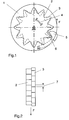
- Figure 1 shows a belt retractor according to the invention for a vehicle seat belt. It essentially consists of a belt reel 1 on which one Belt force F attacks and with a locking toothing 2 with an undercut connected is. About a spring 4 is a locking toothing 3 without an undercut spring loaded against the locking teeth 2. The spring action hurries Locking teeth 3 without undercut of the locking teeth 2 with undercut in Direction of the force F acting on the belt reel during a locking operation.
- two pivotally mounted pawls 5, 6 are pivoted in Position shown, of which the second pawl 6 has an undercut and the first pawl 5 is not.
- the pawls 5, 6 pivot Triggering the locking process for engagement in the locking teeth 2, 3.
- the pawls 5, 6 again after pivoted outside.
- the pivoting in and out can be done in a known form can be realized and is not the subject of the invention.
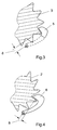
- FIG. 2 shows the relative position of the locking teeth 2, 3 of a belt retractor according to the invention.
- the locking toothing 3 without an undercut leads the locking toothing 2 with an undercut by a spring travel 7, which is determined by the offset of the locking teeth.
- the pawl 5 first engages in the locking teeth 3 without an undercut and blocks it. If the belt force F acting on the belt reel now exceeds a certain limit value F limit , the belt reel 1 with the locking toothing 2 firmly connected to it with an undercut rotates further against the action of the spring force in the spring 4, so that the pawl 6 now also Undercut can come into engagement with the locking teeth 2 with undercut.
- Figure 3 shows the pawl 5 without an undercut of a belt retractor according to the invention in engagement with the locking teeth 3 without an undercut.
- Figure 4 shows the pawl 6 with an undercut of a belt retractor according to the invention in engagement with the locking teeth 2 with an undercut.
- F belt force
- F limits a pulling-in moment acts on the pawl 6 with undercut via the lever arm 8, as a result of which the pawl is pulled in faster and completely and the breaking load can be transmitted safely in the event of a crash.
- the first pawl 5 and the second pawl 6 are one Belt retractor according to the invention according to a first embodiment as two separate jacks shown.
- This embodiment has the advantage that the first Pawl 5 can be inexpensively made of plastic because it is not must be dimensioned for breaking load.
- Figure 6 shows the first pawl 5 and the second pawl 6 one Belt retractor according to the invention according to a further embodiment.
- both pawls 5, 6 a tandem pawl
- the first pawl 5 as Additional cutting edge is formed next to the second pawl 6.
Landscapes
- Engineering & Computer Science (AREA)
- Mechanical Engineering (AREA)
- Automotive Seat Belt Assembly (AREA)
Abstract
Description
- Figur 1 in einer schematischen Seitenansicht einen Gurtaufroller mit eingeschwenkten Sperrklinken in einer erfindungsgemäßen Ausführungsform mit einer Sperrverzahnung ohne Hinterschnitt und einer Sperrverzahnung mit Hinterschnitt;
- Figur 2 in einer schematischen Draufsicht die Sperrverzahnungen des in Figur 1 gezeigten erfindungsgemäßen Gurtaufrollers;
- Figur 3 in einer schematischen abgebrochenen Seitenansicht die Sperrverzahnung ohne Hinterschnitt mit eingeschwenkter Sperrklinke ohne Hinterschnitt des in Figur 1 gezeigten erfindungsgemäßen Gurtaufrollers;
- Figur 4 in einer schematischen abgebrochenen Seitenansicht die Sperrverzahnung mit Hinterschnitt mit eingeschwenkter Sperrklinke mit Hinterschnitt des in Figur 1 gezeigten erfindungsgemäßen Gurtaufrollers;
- Figur 5 in einer schematischen Draufsicht die Sperrklinken eines erfindungsgemäßen Gurtaufrollers in einer Ausführungsform, in der beide Sperrklinken separat ausgeführt sind.
- Figur 6 in einer schematischen Draufsicht die Sperrklinken eines erfindungsgemäßen Gurtaufrollers in einer weiteren Ausführungsform, in der die Sperrklinken als ein Element in Form einer Tandemklinke ausgebildet sind und die erste Sperrklinke als Zusatzschneide neben der zweiten Sperrklinke ausgebildet ist.
Claims (10)
- Gurtaufroller für einen Fahrzeug-Sicherheitsgurt, mit einem Rahmen und einer Gurtspule (1), die im Rahmen drehbar gelagert ist, und wenigstens einer Sperrverzahnung (2, 3), die mit der Gurtspule verbunden ist, wobei eine erste Sperrklinke (5) und eine zweite Sperrklinke (6) vorgesehen sind, die am Rahmen abgestützt sind und in die Sperrverzahnung (2, 3) eingreifen können, wobei die erste Sperrklinke (5) um einen Schwenkpunkt schwenkbar ist, der so angeordnet ist, daß bei in die Sperrverzahnung (3) eingesteuerter Sperrklinke (5) eine virtuelle Linie, die durch den Berührpunkt zwischen der Sperrklinke (5) und der Sperrverzahnung (3) geht und senkrecht auf der Zahnfläche im Berührpunkt steht, zwischen dem Schwenkpunkt und der Drehachse der Gurtspule (1) verläuft, und wobei die zweite Sperrklinke (6) um einen Schwenkpunkt schwenkbar ist, der so angeordnet ist, daß bei in die Sperrverzahnung (2) eingesteuerter Sperrklinke (6) eine virtuelle Linie, die durch den Berührpunkt zwischen der Sperrklinke (6) und der Sperrverzahnung (2) geht und senkrecht auf der Zahnfläche im Berührpunkt steht, auf der von der Drehachse der Gurtspule (1) abgewandten Seite des Schwenkpunktes verläuft.
- Gurtaufroller nach Anspruch 1, dadurch gekennzeichnet, daß bei einem Einsteuervorgang die erste eingesteuerte Sperrklinke (5) in die Sperrverzahnung (2, 3) eingreift und die zweite eingesteuerte Sperrklinke (6) in eine von der Zahnfläche der Sperrverzahnung (2, 3) beabstandete, nicht sperrende Position gelangt.
- Gurtaufroller nach Anspruch 2, dadurch gekennzeichnet, daß die erste Sperrklinke (5) nachgiebig ausgebildet ist.
- Gurtaufroller nach Anspruch 3, dadurch gekennzeichnet, daß die erste Sperrklinke (5) als Zusatzteil auf der zweiten (6) Sperrklinke ausgebildet ist, das mit der zweiten Sperrklinke (6) durch eine Sollbruchstelle verbunden ist.
- Gurtaufroller nach einem der vorhergehenden Ansprüche, dadurch gekennzeichnet, daß eine erste Sperrverzahnung (3) und eine zweite Sperrverzahnung (2) vorgesehen sind, die jeweils mit der Gurtspule verbunden sind, wobei die erste Sperrklinke (5) in die erste Sperrverzahnung (3) und die zweite Sperrklinke (6) in die zweite Sperrverzahnung (2) eingreifen kann.
- Gurtaufroller nach Anspruch 5, dadurch gekennzeichnet, daß die Zähne der ersten Sperrverzahnung (3) ohne Hinterschnitt ausgeführt sind und die Zähne der zweiten Sperrverzahnung (2) mit Hinterschnitt ausgeführt sind.
- Gurtaufroller nach einem der vorhergehenden Ansprüche, dadurch gekennzeichnet, daß die Zähne der ersten Sperrklinke (5) ohne Hinterschnitt ausgeführt sind und die Zähne der zweiten Sperrklinke (6) mit Hinterschnitt ausgeführt sind.
- Gurtaufroller nach Anspruch 5, 6 oder 7, dadurch gekennzeichnet, daß die erste Sperrverzahnung (3) auf einer Sperrscheibe angeordnet ist, die relativ zur zweiten Sperrverzahnung (2) drehbar ist, und daß eine Feder (4) vorgesehen ist, welche die Sperrscheibe relativ zur zweiten Sperrverzahnung (2) in eine Ausgangsstellung beaufschlagt, in der sie der zweiten Sperrverzahnung (2) vorausläuft.
- Gurtaufroller nach einem der vorhergehenden Ansprüche, dadurch gekennzeichnet, daß bei in eine Sperrverzahnung (3) eingesteuerter Sperrklinke (5) eine virtuelle Linie, die durch den Berührpunkt zwischen der Sperrklinke (5) und der Sperrverzahnung (3) geht und senkrecht auf der Zahnfläche im Berührpunkt steht, durch den Schwenkpunkt der Sperrklinke (5) verläuft.
- Gurtaufroller nach einem der vorhergehenden Ansprüche, dadurch gekennzeichnet, daß die erste Sperrklinke aus einem nachgiebigen Werkstoff hergestellt ist.
Applications Claiming Priority (2)
| Application Number | Priority Date | Filing Date | Title |
|---|---|---|---|
| DE20215835U | 2002-10-15 | ||
| DE20215835U DE20215835U1 (de) | 2002-10-15 | 2002-10-15 | Gurtaufroller |
Publications (2)
| Publication Number | Publication Date |
|---|---|
| EP1410960A1 true EP1410960A1 (de) | 2004-04-21 |
| EP1410960B1 EP1410960B1 (de) | 2005-07-13 |
Family
ID=7975990
Family Applications (1)
| Application Number | Title | Priority Date | Filing Date |
|---|---|---|---|
| EP03022626A Expired - Lifetime EP1410960B1 (de) | 2002-10-15 | 2003-10-06 | Gurtaufroller |
Country Status (4)
| Country | Link |
|---|---|
| US (1) | US7051969B2 (de) |
| EP (1) | EP1410960B1 (de) |
| DE (2) | DE20215835U1 (de) |
| ES (1) | ES2244875T3 (de) |
Citations (5)
| Publication number | Priority date | Publication date | Assignee | Title |
|---|---|---|---|---|
| US4522350A (en) * | 1982-11-20 | 1985-06-11 | Britax-Kolb Gmbh & Co. | Safety belt emergency locking retractor |
| WO1989008570A1 (fr) * | 1988-03-17 | 1989-09-21 | Ernst Hans Hellmut | Enrouleurs de ceintures de securite dans des vehicules |
| US5033691A (en) * | 1986-02-03 | 1991-07-23 | Nippon Seiko Kabushiki Kaisha | Webbing retractor |
| DE4232237A1 (de) * | 1992-09-25 | 1994-03-31 | Trw Repa Gmbh | Gurtaufroller |
| DE19648084A1 (de) * | 1996-11-20 | 1998-05-28 | Hs Tech & Design | Sicherheitsgurtaufroller |
Family Cites Families (16)
| Publication number | Priority date | Publication date | Assignee | Title |
|---|---|---|---|---|
| GB1366190A (en) * | 1971-11-09 | 1974-09-11 | Rainsfords Met Prod | Seat belt take-up spool latch |
| AU471215B2 (en) * | 1972-02-22 | 1976-04-15 | Seat belt retractor | |
| GB1507686A (en) * | 1974-10-21 | 1978-04-19 | Fuji Kiko Kk | Vehicle safety-belt retractor |
| SE7702043L (sv) * | 1976-03-02 | 1977-09-03 | Susumu Ubukata | Mekanism till rullbelte |
| DE3008177A1 (de) * | 1980-03-04 | 1981-09-17 | Naamloze Vennootschap Klippan S.A., 3044 Leeuwen | Verriegelungsvorrichtung fuer einen gurtaufroller bei sicherheitsgurten |
| DE3205515A1 (de) * | 1981-11-30 | 1983-06-09 | Repa Feinstanzwerk Gmbh, 7071 Alfdorf | Vorrichtung zum blockieren einer aufrolleinrichtung fuer sicherheitsgurte |
| ZA838354B (en) * | 1982-11-20 | 1984-06-27 | Britax Kolb Gmbh & Co | Safety belt emergency locking retractor |
| DE3908666A1 (de) | 1988-03-29 | 1989-10-12 | Trw Repa Gmbh | Gurtaufroller |
| KR100249998B1 (ko) | 1992-03-24 | 2000-05-01 | 다카다 쥬이치로 | 시이트벨트 리트랙터 |
| JPH05278566A (ja) | 1992-04-06 | 1993-10-26 | Takata Kk | シートベルトリトラクタ |
| US5618006A (en) | 1996-02-23 | 1997-04-08 | Trw Vehicle Safety Systems Inc. | Seat belt retractor with energy management |
| DE19780583C1 (de) | 1996-06-26 | 2001-01-18 | Autolive Dev Ab Vargarda | Gurtaufroller mit regelbarer Kraftbegrenzungseinrichtung |
| DE20004674U1 (de) | 2000-03-14 | 2000-08-03 | TRW Occupant Restraint Systems GmbH & Co. KG, 73553 Alfdorf | Gurtaufroller für einen Fahrzeug-Sicherheitsgurt |
| JP3727514B2 (ja) * | 2000-07-11 | 2005-12-14 | 株式会社東海理化電機製作所 | ウェビング巻取装置 |
| DE20112656U1 (de) | 2001-08-02 | 2001-10-04 | F + W Frey & Winkler GmbH, 75203 Königsbach-Stein | Nasenauflageelement für eine Brille |
| DE20113656U1 (de) | 2001-08-17 | 2002-01-03 | TRW Occupant Restraint Systems GmbH & Co. KG, 73553 Alfdorf | Gurtaufroller für einen Fahrezug-Sicherheitsgurt |
-
2002
- 2002-10-15 DE DE20215835U patent/DE20215835U1/de not_active Expired - Lifetime
-
2003
- 2003-10-06 US US10/679,570 patent/US7051969B2/en not_active Expired - Fee Related
- 2003-10-06 EP EP03022626A patent/EP1410960B1/de not_active Expired - Lifetime
- 2003-10-06 DE DE50300755T patent/DE50300755D1/de not_active Expired - Lifetime
- 2003-10-06 ES ES03022626T patent/ES2244875T3/es not_active Expired - Lifetime
Patent Citations (6)
| Publication number | Priority date | Publication date | Assignee | Title |
|---|---|---|---|---|
| US4522350A (en) * | 1982-11-20 | 1985-06-11 | Britax-Kolb Gmbh & Co. | Safety belt emergency locking retractor |
| US4522350B1 (de) * | 1982-11-20 | 1992-07-14 | Britax Kolb Gmbh & Co | |
| US5033691A (en) * | 1986-02-03 | 1991-07-23 | Nippon Seiko Kabushiki Kaisha | Webbing retractor |
| WO1989008570A1 (fr) * | 1988-03-17 | 1989-09-21 | Ernst Hans Hellmut | Enrouleurs de ceintures de securite dans des vehicules |
| DE4232237A1 (de) * | 1992-09-25 | 1994-03-31 | Trw Repa Gmbh | Gurtaufroller |
| DE19648084A1 (de) * | 1996-11-20 | 1998-05-28 | Hs Tech & Design | Sicherheitsgurtaufroller |
Also Published As
| Publication number | Publication date |
|---|---|
| US7051969B2 (en) | 2006-05-30 |
| ES2244875T3 (es) | 2005-12-16 |
| DE50300755D1 (de) | 2005-08-18 |
| DE20215835U1 (de) | 2003-02-27 |
| US20040069890A1 (en) | 2004-04-15 |
| EP1410960B1 (de) | 2005-07-13 |
Similar Documents
| Publication | Publication Date | Title |
|---|---|---|
| DE2254003C2 (de) | Sicherheitsgurt-Einziehvorrichtung mit Zugentlastung | |
| DE102012019004B4 (de) | Gurtaufroller für einen Sicherheitsgurt | |
| DE3330938C2 (de) | ||
| DE102008063639B4 (de) | Gurtaufroller mit schaltbarem Gurtkraftbegrenzer | |
| WO2018145696A1 (de) | Vorrichtung und verfahren zum betätigen einer parksperre | |
| EP2352660B1 (de) | Fahrzeugsitz mit klinkenanordnung | |
| DE69201846T2 (de) | Hebezeug. | |
| DE69316587T2 (de) | Sicherheitsgurtaufroller | |
| DE3227094C2 (de) | Passives Fahrzeuginsassen-Rückhaltegurtsystem | |
| EP1055568B1 (de) | Gurtaufroller mit Kraftbegrenzer | |
| DE2747592A1 (de) | Verstellbarer, insbesondere in einem fahrzeug, vorzugsweise kraftwagen, anzuordnender sitz | |
| EP3669848B1 (de) | Retraktor-rückhaltesystem, verfahren und verwendung eines solchen, insbesondere zur sicherung von rollstühlen in fahrzeugen | |
| EP1410960B1 (de) | Gurtaufroller | |
| EP1285827A1 (de) | Gurtaufroller für einen Fahrzeugsicherheitsgurt | |
| WO2014139658A1 (de) | Gurtaufroller | |
| EP3290261A1 (de) | Längseinsteller für einen fahrzeugsitz und fahrzeugsitz | |
| DE20217804U1 (de) | Gurtaufroller für einen Fahrzeug-Sicherheitsgurt | |
| DE69414962T2 (de) | Freie Drehung-Steuerungsvorrichtung für ein Hebe- und Zuggerät | |
| DE102016210905B4 (de) | Längseinsteller für einen Fahrzeugsitz und Fahrzeugsitz | |
| EP2342104B1 (de) | Feststellanordnung für eine feststellbremse | |
| DE2747651A1 (de) | Gelenkbeschlag mit verstellbarer rueckenlehne, insbesondere kraftfahrzeugsitz | |
| EP3347626B1 (de) | Parksperrenvorrichtung für ein kraftfahrzeuggetriebe | |
| DE10321730B4 (de) | Gurtaufroller für einen Fahrzeug-Sicherheitsgurt | |
| DE3306544C2 (de) | ||
| DE10357812A1 (de) | Gurtspule für einen Sicherheitsgurtaufroller |
Legal Events
| Date | Code | Title | Description |
|---|---|---|---|
| PUAI | Public reference made under article 153(3) epc to a published international application that has entered the european phase |
Free format text: ORIGINAL CODE: 0009012 |
|
| AK | Designated contracting states |
Kind code of ref document: A1 Designated state(s): AT BE BG CH CY CZ DE DK EE ES FI FR GB GR HU IE IT LI LU MC NL PT RO SE SI SK TR |
|
| AX | Request for extension of the european patent |
Extension state: AL LT LV MK |
|
| GRAP | Despatch of communication of intention to grant a patent |
Free format text: ORIGINAL CODE: EPIDOSNIGR1 |
|
| 17P | Request for examination filed |
Effective date: 20040622 |
|
| GRAS | Grant fee paid |
Free format text: ORIGINAL CODE: EPIDOSNIGR3 |
|
| AKX | Designation fees paid |
Designated state(s): DE ES FR IT |
|
| RAP1 | Party data changed (applicant data changed or rights of an application transferred) |
Owner name: TRW AUTOMOTIVE GMBH |
|
| GRAA | (expected) grant |
Free format text: ORIGINAL CODE: 0009210 |
|
| AK | Designated contracting states |
Kind code of ref document: B1 Designated state(s): DE ES FR IT |
|
| REF | Corresponds to: |
Ref document number: 50300755 Country of ref document: DE Date of ref document: 20050818 Kind code of ref document: P |
|
| REG | Reference to a national code |
Ref country code: ES Ref legal event code: FG2A Ref document number: 2244875 Country of ref document: ES Kind code of ref document: T3 |
|
| ET | Fr: translation filed | ||
| PLBE | No opposition filed within time limit |
Free format text: ORIGINAL CODE: 0009261 |
|
| STAA | Information on the status of an ep patent application or granted ep patent |
Free format text: STATUS: NO OPPOSITION FILED WITHIN TIME LIMIT |
|
| 26N | No opposition filed |
Effective date: 20060418 |
|
| PGFP | Annual fee paid to national office [announced via postgrant information from national office to epo] |
Ref country code: ES Payment date: 20061023 Year of fee payment: 4 |
|
| PGFP | Annual fee paid to national office [announced via postgrant information from national office to epo] |
Ref country code: IT Payment date: 20061031 Year of fee payment: 4 |
|
| REG | Reference to a national code |
Ref country code: FR Ref legal event code: ST Effective date: 20080630 |
|
| PGFP | Annual fee paid to national office [announced via postgrant information from national office to epo] |
Ref country code: FR Payment date: 20061003 Year of fee payment: 4 |
|
| REG | Reference to a national code |
Ref country code: ES Ref legal event code: FD2A Effective date: 20071008 |
|
| PG25 | Lapsed in a contracting state [announced via postgrant information from national office to epo] |
Ref country code: FR Free format text: LAPSE BECAUSE OF NON-PAYMENT OF DUE FEES Effective date: 20071031 Ref country code: ES Free format text: LAPSE BECAUSE OF NON-PAYMENT OF DUE FEES Effective date: 20071008 |
|
| PG25 | Lapsed in a contracting state [announced via postgrant information from national office to epo] |
Ref country code: IT Free format text: LAPSE BECAUSE OF NON-PAYMENT OF DUE FEES Effective date: 20071006 |
|
| PGFP | Annual fee paid to national office [announced via postgrant information from national office to epo] |
Ref country code: DE Payment date: 20191031 Year of fee payment: 17 |
|
| REG | Reference to a national code |
Ref country code: DE Ref legal event code: R081 Ref document number: 50300755 Country of ref document: DE Owner name: ZF AUTOMOTIVE GERMANY GMBH, DE Free format text: FORMER OWNER: TRW AUTOMOTIVE GMBH, 73553 ALFDORF, DE Ref country code: DE Ref legal event code: R082 Ref document number: 50300755 Country of ref document: DE Representative=s name: PRINZ & PARTNER MBB PATENTANWAELTE RECHTSANWAE, DE |
|
| REG | Reference to a national code |
Ref country code: DE Ref legal event code: R119 Ref document number: 50300755 Country of ref document: DE |
|
| PG25 | Lapsed in a contracting state [announced via postgrant information from national office to epo] |
Ref country code: DE Free format text: LAPSE BECAUSE OF NON-PAYMENT OF DUE FEES Effective date: 20210501 |