EP1409874B1 - Rotor pour pompe a palettes - Google Patents
Rotor pour pompe a palettes Download PDFInfo
- Publication number
- EP1409874B1 EP1409874B1 EP02755566A EP02755566A EP1409874B1 EP 1409874 B1 EP1409874 B1 EP 1409874B1 EP 02755566 A EP02755566 A EP 02755566A EP 02755566 A EP02755566 A EP 02755566A EP 1409874 B1 EP1409874 B1 EP 1409874B1
- Authority
- EP
- European Patent Office
- Prior art keywords
- rotor according
- transmission element
- plate
- rotor
- carrier
- Prior art date
- Legal status (The legal status is an assumption and is not a legal conclusion. Google has not performed a legal analysis and makes no representation as to the accuracy of the status listed.)
- Expired - Lifetime
Links
- 230000005540 biological transmission Effects 0.000 claims abstract description 44
- 239000007769 metal material Substances 0.000 claims description 6
- 229910000639 Spring steel Inorganic materials 0.000 claims description 3
- 229910000831 Steel Inorganic materials 0.000 claims description 3
- 239000010959 steel Substances 0.000 claims description 3
- 238000005452 bending Methods 0.000 claims 1
- 239000000463 material Substances 0.000 abstract description 3
- 238000004519 manufacturing process Methods 0.000 abstract 1
- 239000011324 bead Substances 0.000 description 4
- 210000002105 tongue Anatomy 0.000 description 3
- 238000006073 displacement reaction Methods 0.000 description 2
- 239000000446 fuel Substances 0.000 description 2
- 238000000926 separation method Methods 0.000 description 2
- 230000015572 biosynthetic process Effects 0.000 description 1
- 238000010276 construction Methods 0.000 description 1
- 239000007788 liquid Substances 0.000 description 1
- 230000004048 modification Effects 0.000 description 1
- 238000012986 modification Methods 0.000 description 1
- 230000000149 penetrating effect Effects 0.000 description 1
Images


Classifications
-
- F—MECHANICAL ENGINEERING; LIGHTING; HEATING; WEAPONS; BLASTING
- F04—POSITIVE - DISPLACEMENT MACHINES FOR LIQUIDS; PUMPS FOR LIQUIDS OR ELASTIC FLUIDS
- F04C—ROTARY-PISTON, OR OSCILLATING-PISTON, POSITIVE-DISPLACEMENT MACHINES FOR LIQUIDS; ROTARY-PISTON, OR OSCILLATING-PISTON, POSITIVE-DISPLACEMENT PUMPS
- F04C15/00—Component parts, details or accessories of machines, pumps or pumping installations, not provided for in groups F04C2/00 - F04C14/00
- F04C15/0057—Driving elements, brakes, couplings, transmission specially adapted for machines or pumps
- F04C15/0061—Means for transmitting movement from the prime mover to driven parts of the pump, e.g. clutches, couplings, transmissions
- F04C15/0073—Couplings between rotors and input or output shafts acting by interengaging or mating parts, i.e. positive coupling of rotor and shaft
-
- B—PERFORMING OPERATIONS; TRANSPORTING
- B60—VEHICLES IN GENERAL
- B60T—VEHICLE BRAKE CONTROL SYSTEMS OR PARTS THEREOF; BRAKE CONTROL SYSTEMS OR PARTS THEREOF, IN GENERAL; ARRANGEMENT OF BRAKING ELEMENTS ON VEHICLES IN GENERAL; PORTABLE DEVICES FOR PREVENTING UNWANTED MOVEMENT OF VEHICLES; VEHICLE MODIFICATIONS TO FACILITATE COOLING OF BRAKES
- B60T13/00—Transmitting braking action from initiating means to ultimate brake actuator with power assistance or drive; Brake systems incorporating such transmitting means, e.g. air-pressure brake systems
- B60T13/10—Transmitting braking action from initiating means to ultimate brake actuator with power assistance or drive; Brake systems incorporating such transmitting means, e.g. air-pressure brake systems with fluid assistance, drive, or release
- B60T13/24—Transmitting braking action from initiating means to ultimate brake actuator with power assistance or drive; Brake systems incorporating such transmitting means, e.g. air-pressure brake systems with fluid assistance, drive, or release the fluid being gaseous
- B60T13/46—Vacuum systems
-
- F—MECHANICAL ENGINEERING; LIGHTING; HEATING; WEAPONS; BLASTING
- F04—POSITIVE - DISPLACEMENT MACHINES FOR LIQUIDS; PUMPS FOR LIQUIDS OR ELASTIC FLUIDS
- F04C—ROTARY-PISTON, OR OSCILLATING-PISTON, POSITIVE-DISPLACEMENT MACHINES FOR LIQUIDS; ROTARY-PISTON, OR OSCILLATING-PISTON, POSITIVE-DISPLACEMENT PUMPS
- F04C2/00—Rotary-piston machines or pumps
- F04C2/30—Rotary-piston machines or pumps having the characteristics covered by two or more groups F04C2/02, F04C2/08, F04C2/22, F04C2/24 or having the characteristics covered by one of these groups together with some other type of movement between co-operating members
- F04C2/34—Rotary-piston machines or pumps having the characteristics covered by two or more groups F04C2/02, F04C2/08, F04C2/22, F04C2/24 or having the characteristics covered by one of these groups together with some other type of movement between co-operating members having the movement defined in groups F04C2/08 or F04C2/22 and relative reciprocation between the co-operating members
- F04C2/344—Rotary-piston machines or pumps having the characteristics covered by two or more groups F04C2/02, F04C2/08, F04C2/22, F04C2/24 or having the characteristics covered by one of these groups together with some other type of movement between co-operating members having the movement defined in groups F04C2/08 or F04C2/22 and relative reciprocation between the co-operating members with vanes reciprocating with respect to the inner member
-
- F—MECHANICAL ENGINEERING; LIGHTING; HEATING; WEAPONS; BLASTING
- F16—ENGINEERING ELEMENTS AND UNITS; GENERAL MEASURES FOR PRODUCING AND MAINTAINING EFFECTIVE FUNCTIONING OF MACHINES OR INSTALLATIONS; THERMAL INSULATION IN GENERAL
- F16D—COUPLINGS FOR TRANSMITTING ROTATION; CLUTCHES; BRAKES
- F16D1/00—Couplings for rigidly connecting two coaxial shafts or other movable machine elements
- F16D1/06—Couplings for rigidly connecting two coaxial shafts or other movable machine elements for attachment of a member on a shaft or on a shaft-end
- F16D1/08—Couplings for rigidly connecting two coaxial shafts or other movable machine elements for attachment of a member on a shaft or on a shaft-end with clamping hub; with hub and longitudinal key
- F16D1/0852—Couplings for rigidly connecting two coaxial shafts or other movable machine elements for attachment of a member on a shaft or on a shaft-end with clamping hub; with hub and longitudinal key with radial clamping between the mating surfaces of the hub and shaft
- F16D1/0858—Couplings for rigidly connecting two coaxial shafts or other movable machine elements for attachment of a member on a shaft or on a shaft-end with clamping hub; with hub and longitudinal key with radial clamping between the mating surfaces of the hub and shaft due to the elasticity of the hub (including shrink fits)
-
- F—MECHANICAL ENGINEERING; LIGHTING; HEATING; WEAPONS; BLASTING
- F16—ENGINEERING ELEMENTS AND UNITS; GENERAL MEASURES FOR PRODUCING AND MAINTAINING EFFECTIVE FUNCTIONING OF MACHINES OR INSTALLATIONS; THERMAL INSULATION IN GENERAL
- F16D—COUPLINGS FOR TRANSMITTING ROTATION; CLUTCHES; BRAKES
- F16D1/00—Couplings for rigidly connecting two coaxial shafts or other movable machine elements
- F16D1/10—Quick-acting couplings in which the parts are connected by simply bringing them together axially
- F16D1/101—Quick-acting couplings in which the parts are connected by simply bringing them together axially without axial retaining means rotating with the coupling
-
- F—MECHANICAL ENGINEERING; LIGHTING; HEATING; WEAPONS; BLASTING
- F16—ENGINEERING ELEMENTS AND UNITS; GENERAL MEASURES FOR PRODUCING AND MAINTAINING EFFECTIVE FUNCTIONING OF MACHINES OR INSTALLATIONS; THERMAL INSULATION IN GENERAL
- F16D—COUPLINGS FOR TRANSMITTING ROTATION; CLUTCHES; BRAKES
- F16D3/00—Yielding couplings, i.e. with means permitting movement between the connected parts during the drive
- F16D3/16—Universal joints in which flexibility is produced by means of pivots or sliding or rolling connecting parts
- F16D3/18—Universal joints in which flexibility is produced by means of pivots or sliding or rolling connecting parts the coupling parts (1) having slidably-interengaging teeth
-
- F—MECHANICAL ENGINEERING; LIGHTING; HEATING; WEAPONS; BLASTING
- F04—POSITIVE - DISPLACEMENT MACHINES FOR LIQUIDS; PUMPS FOR LIQUIDS OR ELASTIC FLUIDS
- F04C—ROTARY-PISTON, OR OSCILLATING-PISTON, POSITIVE-DISPLACEMENT MACHINES FOR LIQUIDS; ROTARY-PISTON, OR OSCILLATING-PISTON, POSITIVE-DISPLACEMENT PUMPS
- F04C2220/00—Application
- F04C2220/10—Vacuum
-
- F—MECHANICAL ENGINEERING; LIGHTING; HEATING; WEAPONS; BLASTING
- F04—POSITIVE - DISPLACEMENT MACHINES FOR LIQUIDS; PUMPS FOR LIQUIDS OR ELASTIC FLUIDS
- F04C—ROTARY-PISTON, OR OSCILLATING-PISTON, POSITIVE-DISPLACEMENT MACHINES FOR LIQUIDS; ROTARY-PISTON, OR OSCILLATING-PISTON, POSITIVE-DISPLACEMENT PUMPS
- F04C2230/00—Manufacture
- F04C2230/20—Manufacture essentially without removing material
- F04C2230/23—Manufacture essentially without removing material by permanently joining parts together
-
- F—MECHANICAL ENGINEERING; LIGHTING; HEATING; WEAPONS; BLASTING
- F04—POSITIVE - DISPLACEMENT MACHINES FOR LIQUIDS; PUMPS FOR LIQUIDS OR ELASTIC FLUIDS
- F04C—ROTARY-PISTON, OR OSCILLATING-PISTON, POSITIVE-DISPLACEMENT MACHINES FOR LIQUIDS; ROTARY-PISTON, OR OSCILLATING-PISTON, POSITIVE-DISPLACEMENT PUMPS
- F04C2240/00—Components
- F04C2240/60—Shafts
-
- F—MECHANICAL ENGINEERING; LIGHTING; HEATING; WEAPONS; BLASTING
- F05—INDEXING SCHEMES RELATING TO ENGINES OR PUMPS IN VARIOUS SUBCLASSES OF CLASSES F01-F04
- F05C—INDEXING SCHEME RELATING TO MATERIALS, MATERIAL PROPERTIES OR MATERIAL CHARACTERISTICS FOR MACHINES, ENGINES OR PUMPS OTHER THAN NON-POSITIVE-DISPLACEMENT MACHINES OR ENGINES
- F05C2253/00—Other material characteristics; Treatment of material
- F05C2253/22—Reinforcements
Definitions
- the present invention relates mainly to a reduced wear rotor and a pump comprising such a rotor.
- a pump is used in particular in the automotive industry as a source of vacuum for brake assist devices.
- the present invention also relates to combined pumps used for example both as a vacuum source and to supply fuel to a heat engine.
- a rotor according to the preamble of claim 1 and a pump comprising such a rotor is known from the documents US-A-5,707,222 and DE 198 44 904 C .
- the rotor according to these documents comprises a transmission element, a pallet carrier and at least one pallet. Said transmission element transmits a torque to said pallet carrier.
- the pallet carrier comprises an interposing element radially immobilized relative to the pallet carrier and secured to the pallet carrier.
- the interposer is disposed between the bearing surfaces between the transmission member and the pallet carrier to transmit support of the transmission member to the pallet carrier.
- the interposer is resistant to frictional wear of the transmission member during radial movement of the transmission member relative to the pallet carrier.
- the transmission element and the pallet carrier are separate parts and the handling of the rotor with the separate parts is difficult.
- the present invention also relates to a rotor characterized in that the at least one interposition element comprises two parallel fins.
- the present invention also relates to a rotor characterized in that the two fins are connected by a plate.
- the present invention also relates to a rotor characterized in that the fins extend perpendicularly to the plate and the same side of the plate.
- the present invention also relates to a rotor characterized in that the fins are symmetrical with respect to a longitudinal axis to the plate.
- the present invention also relates to a rotor characterized in that the at least one interposing element is secured to a central rod carried by the pallet carrier.
- the present invention also relates to a rotor characterized in that the plate has an orifice in which open at least two tongues cooperating with the central rod carried by the pallet carrier.
- the present invention also relates to a rotor characterized in that the plate comprises fixing means cooperating with second fastening means carried by the pallet carrier.
- the present invention also relates to a rotor characterized in that the fastening means carried by the plate comprise a smaller diameter orifice bordered by a sleeve and in that the fixing means comprise a rod of larger diameter carried by the pallet carrier, said rod being provided with an annular bead protruding on the periphery forming after forced mounting of the plate around the rod and in that the sleeve is disposed after mounting between the bead and the transmission element.
- the present invention also relates to a rotor characterized in that the transmission element is made of metallic material and the pallet carrier is made of plastic.
- the present invention also relates to a rotor characterized in that the transmission element is made of steel.
- the present invention also relates to a rotor characterized in that the interposition element is made of metallic material.
- the present invention also relates to a rotor characterized in that the interposition element is made of spring steel.
- the present invention also relates to a rotor characterized in that the interposition element is made by folding.
- the present invention also relates to a rotor characterized in that the fastening means carried by the plate of the interposition element are made by stamping.
- the present invention also relates to a pump forming at least one vacuum source characterized in that it comprises at least one rotor according to the present invention.
- the present invention also relates to a pump characterized in that the element is driven by an electric motor.
- the present invention also relates to a pump characterized in that the element is driven by a pulley driven by a belt.
- an interposing element 1 comprising at least two fins 3, 5, advantageously monobloc connected by a plate 7.
- the plate 7 is substantially plane first longitudinal dimension 1 and second transverse dimension L much greater than a third dimension e and d longitudinal axis XX ', the plate 7 having two branches 9,11 longitudinally opposite.
- the fins 3.5 extend branches 9,11 in the direction of the arrow F perpendicular to the plane of the plate, opposite one another with respect to the axis XX '.
- the plate 7 also comprises means 13 for fixing the part 1 on a rotor.
- the fastening means comprise at least two tabs 15, 17 opening into an orifice 21 formed in the center of the plate 7.
- the tongues 15, 17 are delimited by four slots 23 formed in the plate 7 extending radially from the orifice 21. direction of the outer periphery of the plate 3 and advantageously parallel between they.
- the slots form a non-zero angle with the longitudinal axis XX 'of the plate 3.
- the piece 1 is fixed locked on the rotor by force-fitting on a part of the rotor cooperating with the orifice 21 thanks to the elastic tabs 15, 17 in a direction transverse to the plane of the plate 7.
- the part 1 is advantageously made of a metallic material, for example spring steel.
- the part 1 is advantageously made by folding.
- a vane pump 33 comprising a rotor 35 ( Figures 3 and 4 ) mounted in a pump body, driven for example by a camshaft of a motor vehicle engine (not shown).
- the rotor comprises a pallet carrier 37, an element 39 for transmitting the torque from the vehicle engine to the pallet carrier, a pallet (not represented) and a support part 1.
- the pallet carrier 37 comprises a body 37 ', advantageously made of plastic material, provided at a first longitudinal end with a first portion 36 of smaller outer diameter and axis YY 'formed by a blind sleeve 41 and at a second end opposite the first end, a second cylindrical portion 38 of larger outer diameter coaxial with the first portion 36 connecting to the first portion 36 of smaller outer diameter by a shoulder 40.
- the sleeve 41 has an inner shape having a cross-sectional cross, preferably four branches. The branches of the cross being separated, advantageously by caps 43, the inner surface of the branches having faces 61 extending radially and parallel to the axis YY '.
- the cylindrical portion 38 of larger outer diameter is provided with a slot 42 capable of receiving a pallet, the slot 42 extending axially along YY 'from a first longitudinal end to a second longitudinal end partially formed by the shoulder 40 , and radially crossing the sleeve 41.
- the body 37 'of the pallet carrier 37 also comprises a rod 45 extending from the bottom of the sleeve 41 towards the open end of the sleeve parallel to the axis YY'.
- the transmission element 39 comprises a base 50 of axis YY 'with four arms 51, 53, 55, 57 arranged in a cross and connected by portions of circular arc 47 and a central opening 49, advantageously oblong allowing the passage of the rod 45.
- the transmission element 39 also has on one face of the base 50 radially opposite lugs 56 projecting axially extending branches 51, 53 along the axis YY '.
- the branches 55, 57 of the transmission member 39 have faces 59, 60 respectively extending in a radial direction and in a direction parallel to the axis YY 'and opposite each other with respect to the 'YY axis'.
- the transmission element 39 is disposed in the internal recess of the sleeve 41 of the body 37 'of the pallet carrier, the arcuate portions 47 opposite the caps 43, the rod 45 penetrating into the opening 49, the face having the lugs 56 being oriented outwards and the faces 59, 60 cooperating each respectively with a face 61 of the inner surface of the sleeve.
- the transmission element is advantageously made of metal material, for example steel.
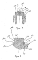
- the pallet carrier 37 comprises an interposing element 1 according to the present invention so that the fins 3, 5 of the element 1 are interposed between the transmission element 39 and the body 37 'of the pallet carrier 37 between the surfaces 59, 60 and the faces 61 and transmit the support of the transmission element 39 to the pallet carrier 37.
- the element 1 is mounted on the pallet carrier 37 so that there is no radial movement of the fins relative to the pallet carrier 37 avoiding frictional wear of the pallet carrier.
- the element 1 is secured to the body 37 'of the pallet carrier by latching the plate 7 connecting the fins 3, 5 in the direction of the arrow on the free end of the rod by means of the tongues 15 17.
- the element 1 is resistant to frictional wear during the displacement of the transmission element relative to the pallet carrier, the body of the pallet carrier then does not undergo the wear previously caused by the friction of the transmission element 39 on the body 37 'of the pallet carrier 37 without modifying the torque transmission. As a result, an elongated life pump is obtained.
- the element 1 advantageously makes it possible to secure the transmission element 39 to the pallet carrier 37 avoiding the separation of the transmission element 39 from the pallet carrier 37 during handling of the pump comprising such a device
- the element 101 comprises first means 113a for securing without radial displacement of the element 101 to the body 137 'of the pallet carrier cooperating with second securing means 113b of the element to the body of the pallet carrier carried by the body of the pallet carrier
- the first means 113b comprise an orifice 121 disposed substantially in the center of the plate 107 and a sleeve 123 bordering the orifice 121 and extending perpendicularly to the surface of the plate 107 in the direction opposite to that in which the fins extend. 103.105.
- the second means 113b are formed by a central rod 145 carried by the body of the pallet carrier 137 of outer diameter D greater than the diameter d of the orifice 121 formed in the plate 107 of the element 101.
- the rod 145 advantageously comprises a bearing surface 150 for the bearing element 101, the surface 150 is formed by an annular recess provided on the periphery of the rod 145 substantially perpendicular to the axis YY 'so that when the transmission element 139 and the support element are arranged in the pallet carrier, a part of the plate 107 surrounding the orifice 121 rests on the recess 150.
- the element 101 is then secured to the pallet carrier after the introduction of the transmission element 139, by force fitting the sleeve 123 around the rod 145.
- Then because of the difference in diameter between that d of the orifice 121 and that D of the rod 145, there ay a temporary elastic reduction of the diameter D of the rod 145.
- the rod 145 is elastically relaxes by forming an annular bead 146 so that the sleeve 123 is disposed after mounting between the transmission member 139 and the bead 146.
- the first fastening means 113a more specifically the sleeve 123 is advantageously made by stamping which gives the connection 148 between the plate 7 and the sleeve 123 a substantially rounded shape which has the advantage during operation of the pump to reduce the risks of wear of the central rod 145 and also to avoid the formation of chips when mounting the element 101 on the pallet carrier
- the means 101 advantageously makes it possible to secure the transmission element 139 to the pallet carrier 137 avoiding the separation of the transmission element 139 from the pallet carrier 137 during manipulation of the pump comprising such a device.
- the present invention is not limited to a single pallet rotor, the rotor according to the present invention being capable of comprising several pallets by a simple modification of the present invention by a person skilled in the art.
- the pump according to the present invention can be driven by a camshaft engine, but also by any device capable of providing a rotational movement.
- the pump according to the present invention forms at least one vacuum source but is also capable of supplying liquid, for example fuel, to a motor.
- the present invention applies in particular to the automotive industry.
- the present invention applies mainly to the braking industry, and more particularly to braking assistance devices.
Landscapes
- Engineering & Computer Science (AREA)
- General Engineering & Computer Science (AREA)
- Mechanical Engineering (AREA)
- Transportation (AREA)
- Rotary Pumps (AREA)
- Applications Or Details Of Rotary Compressors (AREA)
- Structures Of Non-Positive Displacement Pumps (AREA)
- Details And Applications Of Rotary Liquid Pumps (AREA)
- Fuel-Injection Apparatus (AREA)
Abstract
Description
- La présente invention se raporte principalement à un rotor à usure réduite et à une pompe comportant un tel rotor. Une telle pompe est utilisée en particulier dans l'industrie automobile comme source de dépression d'air pour des dispositifs d'assistance au freinage. La présente invention se rapporte également à des pompes combinés utilisées par exemple à la fois comme source de dépression et pour alimenter en carburant un moteur thermique.
- Un rotor selon la préambule de la revendication 1 et une pompe comportant un tel rotor est connu par les document
US-A-5 707 222 etDE 198 44 904 C . Le rotor selon ces documents comprend un élément de transmission, un porte palettes et au moins une palette. Ledit élément de transmission transmet un couple audit porte palettes. Le porte palettes comporte un élément d'interposition immobile radialement par rapport au porte palettes et solidarisé au porte palettes. L'élément d'interposition est disposé entre les surfaces d'appui entre l'élément de transmission et le porte palettes pour transmettre l'appui de l'élément de transmission au porte palettes. L'élément d'interposition est résistant à l'usure par frottement de l'élément de transmission lors du déplacement radial de l'élément de transmission par rapport au porte palettes. L'élément de transmission et le porte palettes sont des pièces séparés et la manipulation du rotor avec les pièces séparés est difficile. - C'est un but de la présente invention de fournir un rotor et une pompe à construction simplifiée et solidité améliorée.
- Ce but est atteint par les caractéristiques de la revendication 1.
- La présente invention a également pour objet un rotor caractérisé en ce que l'au moins un élement d'interposition comporte deux ailettes parallèles.
- La présente invention a aussi pour objet un rotor caractérisé en ce que les deux ailettes sont reliées par un plateau.
- La présente invention a aussi pour objet un rotor caractérisé en ce que les ailettes s'étendent perpendiculairement au plateau et du même côté du plateau.
- La présente invention a aussi pour objet un rotor caractérisé en ce que les ailettes sont symétriques par rapport à un axe longitudinal au plateau.
- La présente invention a aussi pour objet un rotor caractérisé en ce que l'au moins un élément d'interposition est solidarisé à une tige centrale portée par le porte palettes.
- La présente invention a aussi pour objet un rotor caractérisé en ce que le plateau comporte un orifice dan lequel débouchent au moins deux languettes coopérant avec la tige centrale portée par le porte palettes.
- La présente invention a aussi pour objet un rotor caractérisé en ce que le plateau comporte des moyens de fixation coopérant avec des seconds moyens de fixations portés par le porte palettes.
- La présente invention a aussi pour objet un rotor caractérisé en ce que les moyens de fixation portés par le plateau comportent un orifice de plus petit diamètre bordé par un manchon et en ce que les moyens de fixation comportent une tige de plus grand diamètre portés par le porte palettes, ladite tige étant munie d'un bourrelet annulaire en saillie sur la périphérie se formant après montage à force du plateau autour de la tige et en ce que le manchon est disposé après montage entre le bourrelet et l'élément de transmission.
- La présente invention a aussi pour objet un rotor caractérisé en ce que le plateau vient en appui sur une surface d'appui pratiquée dans la périphérie de ladite tige perpendiculairement à l'axe de la tige
- La présente invention a aussi pour objet un rotor caractérisé en ce que l'élément de transmission est en matériau métallique et le porte palettes est en matière plastique.
- La présente invention a aussi pour objet un rotor caractérisé en ce que l'élément de transmission est réalisé en acier.
- La présente invention a aussi pour objet un rotor caractérisé en ce que l'élément d'interposition est réalisé en matériau métallique.
- La présente invention a aussi pour objet un rotor caractérisé en ce que l'élément d'interposition est réalisé en acier à ressort.
- La présente invention a aussi pour objet un rotor caractérisé en ce que l'élément d'interposition est réalisé par pliage.
- La présente invention a aussi pour objet un rotor caractérisé en ce que les moyens de fixation portés par le plateau de l'élément d'interposition sont réalisés par emboutissage.
- La présente invention a également pour objet une pompe formant au moins une source de dépression caractérisée en ce qu'elle comporte au moins un rotor selon la présente invention.
- La présente invention a aussi pour objet une pompe caractérisée en ce que l'élément est entraîné par un arbre à cames
- La présente invention a aussi pour objet une pompe caractérisée en ce que l'élément est entraîné par un moteur électrique.
- La présente invention a aussi pour objet une pompe caractérisée en ce que l'élément est entraîné par une poulie entraîné par une courroie.
- La présente invention sera mieux comprise grâce à de la description qui suivra et des figures annexées sur lesquelles :
- La
figure 1 est une vue de trois quart d'une pompe selon la présente invention. - La
figure 2 est une vue de trois quart d'un premier mode de réalisation d'un élément d'appui selon la présente invention - La
figure 3 est une vue en perspective isométrique d'un rotor comportant l'élément de lafigure 2 ; - La
figure 4 est une vue de dessus de lafigure 3 sans l'élément d'appui ; - La
figure 5 est une vue de trois quart d'un second mode de réalisation d'un rotor selon la présente invention ; - La
figure 6 est une vue en coupe d'un ensemble élément d'appui-élément de transmission selon la présente invention ; - La
figure 7 est une vue de détail de lafigure 6 - On peut voir sur les
figures 1 et 2 , un élément d'interposition 1 comportant au moins deux ailettes 3, 5 , avantageusement monoblocs reliées par un plateau 7. Le plateau 7 est sensiblement plan de première dimension longitudinale 1 et seconde dimension transversale L très supérieures à une troisième dimension e et d'axe longitudinal XX', le plateau 7 comportant deux branches 9,11 longitudinalement opposées. Les ailettes 3,5 s'étendent des branches 9,11 dans la direction de la flèche F perpendiculairement au plan du plateau, opposées l'une de l'autre par rapport à l'axe XX'. - Le plateau 7 comporte également des moyens 13 de fixation de la pièce 1 sur un rotor. Les moyens de fixation comprennent au moins deux languettes 15, 17 débouchant dans un orifice 21 pratiqué au centre du plateau 7. Les languettes 15, 17 sont délimitées par quatre fentes 23 pratiquées dans le plateau 7 s'étendant radialement de l'orifice 21 en direction de la périphérie extérieure du plateau 3 et avantageusement parallèles entre elles. Avantageusement, les fentes forment un angle non nul avec l'axe longitudinale XX' du plateau 3.
- La pièce 1 est fixée bloquée sur le rotor par emmanchement à force sur une pièce du rotor coopérant avec l'orifice 21 grâce aux languettes 15,17 élastiques dans un sens transversale au plan du plateau 7.
- La pièce 1 est avantageusement réalisée en un matériau métallique, par exemple en acier à ressort.
- La pièce 1 est avantageusement réalisée par pliage.
- Sur la
figure 1 , on peut voir une pompe à palettes 33 selon la présente invention, comportant un rotor 35 (figures 3 et 4 ) monté dans un corps de pompe, entraîné par exemple par un arbre à cames d'un moteur de véhicule automobile (non représentés). Le rotor comporte un porte palettes 37, un élément 39 de transmission du couple du moteur du véhicule au porte palettes, une palette (non représentée) et un pièce d'appui 1. Le porte palettes 37 comporte un corps 37', avantageusement réalisé en matière plastique, muni à une première extrémité longitudinale d'une première partie 36 de plus petit diamètre extérieur et d'axe YY' formée par un manchon borgne 41 et à une seconde extrémité opposée à la première extrémité, d'une seconde partie cylindrique 38 de plus grand diamètre extérieur coaxiale à la première partie 36 se raccordant à la première partie 36 de plus petit diamètre extérieur par un épaulement 40. Le manchon 41 a une forme intérieure ayant une section transversale en forme de croix, avantageusement à quatre branches. Les branches de la croix étant séparées, avantageusement par des calottes 43, la surface intérieure des branches comportant des faces 61 s'étendant radialement et parallèlement à l'axe YY'. La partie cylindrique 38 de plus grand diamètre extérieur est munie d'une fente 42 susceptible de recevoir une palette, la fente 42 s'étendant axialement suivant YY' d'une première extrémité longitudinale à une seconde extrémité longitudinale formée partiellement par l'épaulement 40, et traversant radialement le manchon 41. - Le corps 37' du porte palettes 37 comporte également une tige 45 s'étendant du fond du manchon 41 vers l'extrémité ouverte du manchon parallèlement à l'axe YY'.
- L'élément de transmission 39 comporte une base 50 d'axe YY' à quatre branches 51, 53, 55, 57 disposées en croix et reliées par des portions d'arc de cercle 47 et une ouverture 49 centrale, avantageusement oblongue permettant le passage de la tige 45. L'élément de transmission 39 comporte également sur une face de la base 50 des ergots 56 radialement opposés faisant saillis en s'étendant axialement des branches 51, 53 selon l'axe YY'.
Les branches 55, 57 de l'élément de transmission 39 comportent des faces 59, 60 respectivement s'étendant dans une direction radiale et dans une direction parallèle à l'axe YY' et opposées l'une de l'autre par rapport à l'axe YY'. - L'élément de transmission 39 est disposé dans l'évidement intérieur du manchon 41 du corps 37' du porte palettes, les portions d'arc de cercle 47 en vis-à-vis des calottes 43, la tige 45 pénétrant dans l'ouverture 49, la face comportant les ergots 56 étant orientée vers l'extérieur et les faces 59, 60 coopérant chacune respectivement avec une face 61 de la surface intérieur du manchon.
- L'élément de transmission est avantageusement réalisé en matériau métallique, par exemple en acier.
- Le porte palettes 37 comporte un élément d'interposition 1 selon la présente invention de manière à ce que les ailettes 3, 5 de l'élément 1 viennent s'intercaler entre l'élément de transmission 39 et le corps 37' du porte palettes 37 entre les surfaces 59, 60 et les faces 61 et transmettent l'appui de l'élément de transmission 39 au porte palettes 37. L'élément 1 est monté sur la porte palettes 37 de manière à ce qu'il n'y ai pas de mouvement radial des ailettes par rapport au porte palettes 37 évitant l'usure par frottement du porte palettes. Selon la premier mode de réalisation, l'élément 1 est solidarisé au corps 37' du porte palettes par encliquetage du plateau 7 reliant les ailettes 3, 5 dans la direction de la flèche sur l'extrémité libre de la tige au moyen des languettes 15,17.
- L'élément 1 est résistant à l'usure par frottement lors du déplacement de l'élément de transmission par rapport au porte palettes, le corps du porte palettes ne subit alors pas l'usure provoquée auparavant par le frottement de l'élément de transmission 39 sur le corps 37' du porte palettes 37 sans modifier la transmission du couple. Par conséquent, on obtient une pompe à durée de vie allongée.
- De plus, l'élément 1 permet avantageusement de solidariser l'élément de transmission 39 au porte palettes 37 évitant la séparation de l'élément de transmission 39 du porte palettes 37 lors de manipulations de la pompe comportant un tel dispositif
- Sur la
figure 5 , on peut voir un second mode de réalisation d'un élément 101 selon la présente invention, celui-ci diffère de l'élément 1 selon le premier mode de réalisation par les moyens de solidarisation de l'élément au porte palettes. - Par conséquent nous ne décrirons en détail que les moyens de solidarisation.
- L'élément 101 comporte des premiers moyens 113a de solidarisation sans déplacement radial de l'élément 101 au corps 137' du porte palettes coopérant avec des seconds moyens de solidarisation 113b de l'élément au corps du porte palettes porté par le corps du porte palettes, Les premiers moyens 113b comportent un orifice 121 disposé sensiblement au centre du plateau 107 et un manchon 123 bordant l'orifice 121 et s'étendant perpendiculairement à la surface du plateau 107 dans la direction opposée à celle dans la quelle s'étendent les ailettes 103,105.
- Sur la
figure 6 et sur lafigure 7 qui représente un détail référencé A agrandi de lafigure 6 , on peut voir le rotor d'axe YY' selon le deuxième mode de réalisation comportant les seconds moyens 113b. Les seconds moyens 113b sont formés par une tige centrale 145 portée par le corps du porte palettes 137 de diamètre extérieure D supérieure au diamètre d de l'orifice 121 pratiqué dans le plateau 107 de l'élément 101. - La tige 145 comporte avantageusement une surface d'appui 150 pour l'élément d'appui 101, la surface 150 est formé par un décrochement annulaire pratiqué sur la périphérie de la tige 145 sensiblement perpendiculairement à l'axe YY' de manière à ce que lorsque l'élément de transmission 139 et l'élément d'appui sont disposés dans le porte palettes, une partie du plateau 107 entourant l'orifice 121 repose sur le décrochement 150.
- L'élément 101 est alors solidarisé au porte palettes après la mise en place de l'élément de transmission 139, par emmanchement à force du manchon 123 autour de la tige 145. Lors de l'assemblage, du fait de la différence de diamètre entre celui d de l'orifice 121 et celui D de la tige 145, il a y une réduction élastique temporaire du diamètre D de la tige 145. Puis lorsque le plateau 107 arrive en appui contre la surface annulaire d'appui 150, la tige 145 se détend élastiquement en formant un bourrelet annulaire 146 de manière à ce que le manchon 123 soit disposé après montage entre l'élément de transmission 139 et le bourrelet 146.
- De plus les premiers moyens de solidarisation 113a, plus précisément le manchon 123 est avantageusement est réalisé par emboutissage ce qui confère au raccord 148 entre le plateau 7 et le manchon 123 une forme sensiblement arrondie qui a pour avantage lors du fonctionnement de la pompe de réduire les risques d'usure de la tige centrale 145 et également d'éviter la formation de copeaux lors du montage de l'élément 101 sur le porte palettes
- De plus, le moyen 101 permet avantageusement de solidariser l'élément de transmission 139 au porte palettes 137 évitant la séparation de l'élément de transmission 139 du porte palettes 137 lors de manipulations de la pompe comportant un tel dispositif.
- Il est bien entendu que la présente invention ne se limite pas un rotor à une seule palette, le rotor selon la présent invention étant susceptible de comporter plusieurs palettes par une modification simple de la présente invention par un homme du métier.
- Il est également bien entendu que la pompe selon la présente invention peut être entraînée par un arbre à cames de moteur thermique mais également par tout dispositif susceptible de fournir un mouvement de rotation.
- Il est également bien entendu que la pompe selon la présente invention forme au moins une source de dépression mais est également susceptible d'alimenter en liquide, par exemple en carburant un moteur.
- La présente invention s'applique notamment à l'industrie automobile.
- La présente invention s'applique principalement à l'industrie du freinage, et plus particulièrement aux dispositifs d'assistance au freinage.
Claims (20)
- Rotor comprenant un élément de transmission (39;139), un porte palettes (37;137) et au moins une palette, ledit élément de transmission (39;139) transmettant un couple audit porte palettes (37;137), le porte palettes (37;137) comportant au moins un élément d'interposition (1;101) immobile radialement par rapport au porte palettes (37;137) et solidarisé sur le porte palettes (37;137), l'au moins un élément d'interposition étant disposé entre les surfaces d'appui entre l'élément de transmission (39;139) et le porte palettes (37;137) pour transmettre l'appui de l'élément de transmission (39;139) au porte palettes (37;137), ledit au moins un élément d'interposition (1;101) étant résistant à l'usure par frottement de l'élément de transmission (39;139) lors du déplacement radial de l'élément de transmission (39;139) par rapport au porte palettes (37;137), caractérisé en ce que l'élément de transmission (39;139) est solidarisé au porte palettes (37;137) par l'au moins un élément d'interposition.
- Rotor selon la revendication 1 caractérisé en ce que l'au moins un élément d'interposition (1,101) comporte deux ailettes parallèles (3,5,103,105).
- Rotor selon la revendication 2 caractérisé en ce que les deux ailettes (3,103,5,105) sont reliées par un plateau(7,107).
- Rotor selon la revendication 3 caractérisé en ce que les ailettes (3,103,5,105) s'étendent perpendiculairement au plateau (7,107) et du même côté du plateau (7,107).
- Rotor selon la revendications 3 ou 4 caractérisé en ce que les ailettes (3,5,103,105) sont symétriques par rapport à un axe longitudinale (XX') du plateau (7,107).
- Rotor selon l'une quelconque des revendications de 3 à 5 caractérisé en ce que l'au moins un élément d'interposition est solidarisé à une tige centrale (45,145) porté par le porte palettes (27,137).
- Rotor selon la revendication précédente caractérisé en ce que le plateau (7) comporte un orifice (21) dan lequel débouchent au moins deux languettes(15,17) coopérant avec la tige centrale (45) porté par le porte palettes (37).
- Rotor selon la revendication 6 caractérisé en ce que le plateau comporte des moyens de fixation (113a) coopérant avec des seconds moyens de fixations (113b) portés par le porte palettes.
- Rotor selon la revendication 8 caractérisé en ce que les moyens de fixation (113a) portés par le plateau (107) comportent un orifice (121) de plus petit diamètre (d) bordé par un manchon (123) et en ce que les moyens de fixation (113b) comportent une tige (145) de plus grand diamètre (D) portés par le porte palettes, ladite tige étant munie d'un bourrelet annulaire (146) en saillie sur la périphérie se formant après montage à force du plateau (107) autour de la tige (145) et en ce que le manchon est disposé après montage entre le bourrelet (146) et l'élément de transmission.
- Rotor selon la revendication précédente caractérisé en ce que le plateau (107) vient en appui sur une surface d'appui (150) pratiquée dans la périphérie de ladite tige (145) perpendiculairement à l'axe de la tige
- Rotor selon l'une quelconque des revendications précédentes caractérisé en ce que l'élément de transmission (39,139) est en matériau métallique et le porte palettes (37,137) est en matière plastique.
- Rotor selon la revendication précédente caractérisé en ce que l'élément de transmission est réalisé en acier.
- Rotor selon l'une quelconque des revendications précédentes caractérisé en ce que l'élément d'interposition (1,101) est réalisé en matériau métallique.
- Rotor selon la revendication précédente caractérisé en ce que l'élément d'interposition est réalisé en acier à ressort.
- Rotor selon la revendication 13 ou 14 caractérisé en ce que l'élément d'interposition (1,101) est réalisé par pliage.
- Rotor selon l'une quelconque des revendications de 9 ou 10 caractérisé en ce que les moyens de fixation (113a) portés par le plateau de l'élément d'interposition (101) sont réalisés par emboutissage.
- Pompe formant au moins une source de dépression caractérisée en ce qu'elle comporte au moins un rotor selon l'une des revendications précédentes.
- Pompe selon la revendication 15 caractérisée en ce que l'élément de transmission (39,139) est entraîné par un arbre à cames.
- Pompe selon la revendication 15 caractérisée en ce que l'élément de transmission (9,139) est entraîné par un moteur électrique.
- Pompe selon la revendication 15 caractérisée en ce que l'élément de transmission (39,139) est entraîné par une poulie entraîné par une courroie.
Applications Claiming Priority (3)
| Application Number | Priority Date | Filing Date | Title |
|---|---|---|---|
| ITTO20010521 | 2001-06-01 | ||
| IT2001TO000521A ITTO20010521A1 (it) | 2001-06-01 | 2001-06-01 | Rotore soggetto a ridotta usura, e pompa comprendente tale rotore. |
| PCT/IB2002/003448 WO2002097274A2 (fr) | 2001-06-01 | 2002-05-29 | Rotor pour pompe a palettes |
Publications (2)
| Publication Number | Publication Date |
|---|---|
| EP1409874A2 EP1409874A2 (fr) | 2004-04-21 |
| EP1409874B1 true EP1409874B1 (fr) | 2012-07-18 |
Family
ID=11458916
Family Applications (1)
| Application Number | Title | Priority Date | Filing Date |
|---|---|---|---|
| EP02755566A Expired - Lifetime EP1409874B1 (fr) | 2001-06-01 | 2002-05-29 | Rotor pour pompe a palettes |
Country Status (10)
| Country | Link |
|---|---|
| EP (1) | EP1409874B1 (fr) |
| JP (1) | JP4276064B2 (fr) |
| CN (1) | CN1325799C (fr) |
| AU (2) | AU2002361947A1 (fr) |
| ES (1) | ES2394298T3 (fr) |
| IT (1) | ITTO20010521A1 (fr) |
| MX (1) | MXPA03011069A (fr) |
| PL (1) | PL206620B1 (fr) |
| RU (1) | RU2294455C2 (fr) |
| WO (2) | WO2003030296A2 (fr) |
Families Citing this family (11)
| Publication number | Priority date | Publication date | Assignee | Title |
|---|---|---|---|---|
| DE10260546A1 (de) * | 2002-12-21 | 2004-07-01 | Ina-Schaeffler Kg | Brennkraftmaschine mit einer Vorrichtung zur hydraulischen Drehwinkelverstellung ihrer Nockenwelle gegenüber ihrer Kurbelwelle sowie mit einer Vakuumpumpe für einen Servoverbraucher, insbesondere für einen Bremskraftverstärker |
| EP1681218A1 (fr) * | 2005-01-15 | 2006-07-19 | LuK Automobiltechnik GmbH & Co. KG | Servofrein à pression négative |
| ITTO20060263A1 (it) * | 2006-04-11 | 2007-10-12 | Vhit Spa | Rotore per pompa a palette in materia plastica rinforzata da lamine metalliche |
| CN102562934B (zh) * | 2011-05-18 | 2013-04-17 | 中联重科股份有限公司 | 缓冲装置及具有该缓冲装置的臂架的防后倾装置 |
| EP2746532B1 (fr) | 2012-12-19 | 2018-02-14 | Pierburg Pump Technology GmbH | Agencement de rotor pour une pompe à vide ainsi que la pompe à vide dotée d'un tel agencement de rotor |
| CN105142940B (zh) * | 2013-03-27 | 2017-03-08 | 北京京西重工有限公司 | 液压悬挂系统 |
| IT201800005866A1 (it) * | 2018-05-30 | 2019-11-30 | Pompa volumetrica rotativa | |
| IT201900014604A1 (it) * | 2019-08-09 | 2021-02-09 | Vhit S P A Soc Unipersonale | Rotore a ridotta usura |
| IT201900014601A1 (it) * | 2019-08-09 | 2021-02-09 | Vhit S P A Soc Unipersonale | Rotore a ridotta usura |
| DE102019124262A1 (de) * | 2019-09-10 | 2021-03-11 | HELLA GmbH & Co. KGaA | Flügelzellenpumpe |
| CN112780603B (zh) * | 2019-11-07 | 2024-06-21 | 罗伯特·博世有限公司 | 连接组件和包括该连接组件的真空泵 |
Family Cites Families (8)
| Publication number | Priority date | Publication date | Assignee | Title |
|---|---|---|---|---|
| US3955A (en) * | 1845-03-15 | Power-loom | ||
| DE2336307A1 (de) * | 1973-07-17 | 1975-01-30 | Bosch Gmbh Robert | Pumpeneinheit |
| US4286442A (en) * | 1979-02-07 | 1981-09-01 | Barry Wright Corporation | Flexible coupling |
| IT1279128B1 (it) * | 1995-04-19 | 1997-12-04 | Alliedsignal Automotive It Spa | Pompa rotativa a paletta unica elastica |
| DE19519841B4 (de) * | 1995-05-31 | 2004-02-12 | Luk Automobiltechnik Gmbh & Co. Kg | Flügelzellenpumpe |
| DE19844904C1 (de) * | 1998-09-30 | 2000-02-17 | Luk Automobiltech Gmbh & Co Kg | Vakuumpumpe |
| JP4120092B2 (ja) * | 1999-05-21 | 2008-07-16 | 株式会社デンソー | 車両用真空ポンプの継手 |
| DE19942221A1 (de) * | 1999-09-03 | 2001-03-15 | Luk Fahrzeug Hydraulik | Einrichtung zur Förderung eines gasförmigen oder flüssigen Mediums |
-
2001
- 2001-06-01 IT IT2001TO000521A patent/ITTO20010521A1/it unknown
-
2002
- 2002-05-29 MX MXPA03011069A patent/MXPA03011069A/es not_active Application Discontinuation
- 2002-05-29 WO PCT/EP2002/006929 patent/WO2003030296A2/fr not_active Ceased
- 2002-05-29 RU RU2003136732/06A patent/RU2294455C2/ru not_active IP Right Cessation
- 2002-05-29 AU AU2002361947A patent/AU2002361947A1/en not_active Abandoned
- 2002-05-29 PL PL374324A patent/PL206620B1/pl not_active IP Right Cessation
- 2002-05-29 WO PCT/IB2002/003448 patent/WO2002097274A2/fr not_active Ceased
- 2002-05-29 AU AU2002321775A patent/AU2002321775B2/en not_active Ceased
- 2002-05-29 EP EP02755566A patent/EP1409874B1/fr not_active Expired - Lifetime
- 2002-05-29 CN CNB028145259A patent/CN1325799C/zh not_active Expired - Lifetime
- 2002-05-29 ES ES02755566T patent/ES2394298T3/es not_active Expired - Lifetime
- 2002-05-29 JP JP2003500421A patent/JP4276064B2/ja not_active Expired - Fee Related
Also Published As
| Publication number | Publication date |
|---|---|
| WO2003030296A2 (fr) | 2003-04-10 |
| RU2294455C2 (ru) | 2007-02-27 |
| WO2003030296A3 (fr) | 2003-09-25 |
| PL206620B1 (pl) | 2010-08-31 |
| ITTO20010521A1 (it) | 2002-12-01 |
| RU2003136732A (ru) | 2005-05-27 |
| CN1533479A (zh) | 2004-09-29 |
| ITTO20010521A0 (it) | 2001-06-01 |
| JP4276064B2 (ja) | 2009-06-10 |
| WO2002097274A3 (fr) | 2003-06-05 |
| PL374324A1 (en) | 2005-10-17 |
| ES2394298T3 (es) | 2013-01-30 |
| CN1325799C (zh) | 2007-07-11 |
| AU2002361947A1 (en) | 2003-04-14 |
| JP2004526905A (ja) | 2004-09-02 |
| MXPA03011069A (es) | 2005-06-22 |
| WO2002097274A2 (fr) | 2002-12-05 |
| EP1409874A2 (fr) | 2004-04-21 |
| AU2002321775B2 (en) | 2008-09-04 |
| WO2002097274A8 (fr) | 2004-03-04 |
Similar Documents
| Publication | Publication Date | Title |
|---|---|---|
| EP0751305A1 (fr) | Dispositif pour la fixation d'un élément appartenant à un mécanisme d'essuie-glace sur la caisse d'un véhicule automobile | |
| FR2627821A1 (fr) | Dispositif de fixation anti-vibratoire, notamment d'une plaque porte-charbons sur le flasque porte palier d'un moteur electrique | |
| FR2839136A1 (fr) | Dispositif de raccordement etanche, en particulier pour un circuit d'admission d'air de moteur de vehicule automobile | |
| EP1409874A2 (fr) | Rotor pour pompe a palettes | |
| FR2762058A1 (fr) | Dispositif d'accouplement elastique entre deux arbres sensiblement alignes | |
| EP0349367B1 (fr) | Contacteur électrique pour servomoteur pneumatique de freinage | |
| FR2768794A1 (fr) | Embrayage de verrouillage pour un appareil d'accouplement hydrocinetique, notamment de vehicule automobile | |
| FR2572480A1 (fr) | Couvercle et mecanisme d'embrayage le comportant | |
| FR2968697A1 (fr) | Dispositif de liaison d'un entrainement de hayon de vehicule | |
| EP2475557B1 (fr) | Piston d'actionneur de servofrein et servofrein equipe d'un tel piston. | |
| EP1870602B1 (fr) | Pièce d'assemblage de deux éléments entre eux, dispositif d'assemblage associé et application au domaine de l'automobile | |
| EP4107406B1 (fr) | Mécanisme à liaison hélicoïdale pour piston d'étrier de frein électromécanique à montage simplifieé et procédé de fabrication d'un tel mécanisme | |
| FR3047528A1 (fr) | Dispositif de progressivite pour disque de friction d'embrayage et disque de friction integrant un tel dispositif | |
| FR2767768A1 (fr) | Dispositif amortisseur notamment pour le montage d'une platine de support d'un mecanisme d'essuie-glace | |
| EP1588897B1 (fr) | Elément de fixation et véhicule correspondant | |
| EP0360650B1 (fr) | Butée de débrayage, notamment pour véhicules automobiles | |
| EP3683150B1 (fr) | Dispositif de liaison pivotante entre au moins deux pièces, aéronef comprenant un capot équipé dudit dispositif de liaison pivotante | |
| WO2002021021A1 (fr) | Appareil d'accouplement hydrocinetique, notamment pour vehicule automobile | |
| FR2900704A1 (fr) | Embrayage a friction perfectionne, en particulier pour vehicule automobile, rondelle de guidage d'amortisseur d'embrayage a friction, et procede de montage d'un embrayage a friction | |
| FR2688557A1 (fr) | Mecanisme d'embrayage a diaphragme, notamment pour vehicule automobile et son procede de fabrication. | |
| EP1649472B1 (fr) | Electrovalve, procede d'assemblage d'un solenoïde sur ladite electrovalve, et procede de desassemblage du solenoïde de ladite electrovalve | |
| EP4416397B1 (fr) | Dispositif de fixation | |
| FR2764952A1 (fr) | Systeme d'entrainement pour un essuie-glace de vehicule automobile comportant une articulation a rotule perfectionnee | |
| FR3091915A1 (fr) | « Pièce métallique pour un moteur à combustion interne et ensemble comportant une telle pièce » | |
| EP0625636A1 (fr) | Pièce métallique creuse pourvue d'un joint d'étanchéité, telle qu'un carter inferieur de moteur de véhicule automobile |
Legal Events
| Date | Code | Title | Description |
|---|---|---|---|
| PUAI | Public reference made under article 153(3) epc to a published international application that has entered the european phase |
Free format text: ORIGINAL CODE: 0009012 |
|
| 17P | Request for examination filed |
Effective date: 20040102 |
|
| AK | Designated contracting states |
Kind code of ref document: A2 Designated state(s): AT BE CH CY DE DK ES FI FR GB GR IE IT LI LU MC NL PT SE TR |
|
| AX | Request for extension of the european patent |
Extension state: AL LT LV MK RO SI |
|
| 17Q | First examination report despatched |
Effective date: 20060627 |
|
| GRAP | Despatch of communication of intention to grant a patent |
Free format text: ORIGINAL CODE: EPIDOSNIGR1 |
|
| GRAS | Grant fee paid |
Free format text: ORIGINAL CODE: EPIDOSNIGR3 |
|
| GRAA | (expected) grant |
Free format text: ORIGINAL CODE: 0009210 |
|
| AK | Designated contracting states |
Kind code of ref document: B1 Designated state(s): AT BE CH CY DE DK ES FI FR GB GR IE IT LI LU MC NL PT SE TR |
|
| REG | Reference to a national code |
Ref country code: GB Ref legal event code: FG4D Free format text: NOT ENGLISH |
|
| REG | Reference to a national code |
Ref country code: CH Ref legal event code: EP |
|
| REG | Reference to a national code |
Ref country code: AT Ref legal event code: REF Ref document number: 567103 Country of ref document: AT Kind code of ref document: T Effective date: 20120815 Ref country code: IE Ref legal event code: FG4D Free format text: LANGUAGE OF EP DOCUMENT: FRENCH |
|
| REG | Reference to a national code |
Ref country code: DE Ref legal event code: R096 Ref document number: 60243340 Country of ref document: DE Effective date: 20120913 |
|
| REG | Reference to a national code |
Ref country code: NL Ref legal event code: VDEP Effective date: 20120718 |
|
| REG | Reference to a national code |
Ref country code: AT Ref legal event code: MK05 Ref document number: 567103 Country of ref document: AT Kind code of ref document: T Effective date: 20120718 |
|
| REG | Reference to a national code |
Ref country code: ES Ref legal event code: FG2A Ref document number: 2394298 Country of ref document: ES Kind code of ref document: T3 Effective date: 20130130 |
|
| PG25 | Lapsed in a contracting state [announced via postgrant information from national office to epo] |
Ref country code: AT Free format text: LAPSE BECAUSE OF FAILURE TO SUBMIT A TRANSLATION OF THE DESCRIPTION OR TO PAY THE FEE WITHIN THE PRESCRIBED TIME-LIMIT Effective date: 20120718 Ref country code: CY Free format text: LAPSE BECAUSE OF FAILURE TO SUBMIT A TRANSLATION OF THE DESCRIPTION OR TO PAY THE FEE WITHIN THE PRESCRIBED TIME-LIMIT Effective date: 20120718 Ref country code: FI Free format text: LAPSE BECAUSE OF FAILURE TO SUBMIT A TRANSLATION OF THE DESCRIPTION OR TO PAY THE FEE WITHIN THE PRESCRIBED TIME-LIMIT Effective date: 20120718 |
|
| PG25 | Lapsed in a contracting state [announced via postgrant information from national office to epo] |
Ref country code: PT Free format text: LAPSE BECAUSE OF FAILURE TO SUBMIT A TRANSLATION OF THE DESCRIPTION OR TO PAY THE FEE WITHIN THE PRESCRIBED TIME-LIMIT Effective date: 20121119 Ref country code: GR Free format text: LAPSE BECAUSE OF FAILURE TO SUBMIT A TRANSLATION OF THE DESCRIPTION OR TO PAY THE FEE WITHIN THE PRESCRIBED TIME-LIMIT Effective date: 20121019 Ref country code: SE Free format text: LAPSE BECAUSE OF FAILURE TO SUBMIT A TRANSLATION OF THE DESCRIPTION OR TO PAY THE FEE WITHIN THE PRESCRIBED TIME-LIMIT Effective date: 20120718 |
|
| PG25 | Lapsed in a contracting state [announced via postgrant information from national office to epo] |
Ref country code: NL Free format text: LAPSE BECAUSE OF FAILURE TO SUBMIT A TRANSLATION OF THE DESCRIPTION OR TO PAY THE FEE WITHIN THE PRESCRIBED TIME-LIMIT Effective date: 20120718 |
|
| PG25 | Lapsed in a contracting state [announced via postgrant information from national office to epo] |
Ref country code: DK Free format text: LAPSE BECAUSE OF FAILURE TO SUBMIT A TRANSLATION OF THE DESCRIPTION OR TO PAY THE FEE WITHIN THE PRESCRIBED TIME-LIMIT Effective date: 20120718 |
|
| PLBE | No opposition filed within time limit |
Free format text: ORIGINAL CODE: 0009261 |
|
| STAA | Information on the status of an ep patent application or granted ep patent |
Free format text: STATUS: NO OPPOSITION FILED WITHIN TIME LIMIT |
|
| 26N | No opposition filed |
Effective date: 20130419 |
|
| REG | Reference to a national code |
Ref country code: DE Ref legal event code: R097 Ref document number: 60243340 Country of ref document: DE Effective date: 20130419 |
|
| BERE | Be: lapsed |
Owner name: VHIT S.P.A. Effective date: 20130531 |
|
| PG25 | Lapsed in a contracting state [announced via postgrant information from national office to epo] |
Ref country code: MC Free format text: LAPSE BECAUSE OF FAILURE TO SUBMIT A TRANSLATION OF THE DESCRIPTION OR TO PAY THE FEE WITHIN THE PRESCRIBED TIME-LIMIT Effective date: 20120718 |
|
| REG | Reference to a national code |
Ref country code: CH Ref legal event code: PL |
|
| PG25 | Lapsed in a contracting state [announced via postgrant information from national office to epo] |
Ref country code: CH Free format text: LAPSE BECAUSE OF NON-PAYMENT OF DUE FEES Effective date: 20130531 Ref country code: LI Free format text: LAPSE BECAUSE OF NON-PAYMENT OF DUE FEES Effective date: 20130531 |
|
| REG | Reference to a national code |
Ref country code: IE Ref legal event code: MM4A |
|
| PG25 | Lapsed in a contracting state [announced via postgrant information from national office to epo] |
Ref country code: BE Free format text: LAPSE BECAUSE OF NON-PAYMENT OF DUE FEES Effective date: 20130531 |
|
| PG25 | Lapsed in a contracting state [announced via postgrant information from national office to epo] |
Ref country code: IE Free format text: LAPSE BECAUSE OF NON-PAYMENT OF DUE FEES Effective date: 20130529 |
|
| PG25 | Lapsed in a contracting state [announced via postgrant information from national office to epo] |
Ref country code: TR Free format text: LAPSE BECAUSE OF FAILURE TO SUBMIT A TRANSLATION OF THE DESCRIPTION OR TO PAY THE FEE WITHIN THE PRESCRIBED TIME-LIMIT Effective date: 20120718 |
|
| PG25 | Lapsed in a contracting state [announced via postgrant information from national office to epo] |
Ref country code: LU Free format text: LAPSE BECAUSE OF NON-PAYMENT OF DUE FEES Effective date: 20130529 |
|
| REG | Reference to a national code |
Ref country code: FR Ref legal event code: PLFP Year of fee payment: 15 |
|
| REG | Reference to a national code |
Ref country code: FR Ref legal event code: PLFP Year of fee payment: 16 |
|
| PGFP | Annual fee paid to national office [announced via postgrant information from national office to epo] |
Ref country code: GB Payment date: 20170524 Year of fee payment: 16 |
|
| PGFP | Annual fee paid to national office [announced via postgrant information from national office to epo] |
Ref country code: ES Payment date: 20170601 Year of fee payment: 16 |
|
| REG | Reference to a national code |
Ref country code: FR Ref legal event code: PLFP Year of fee payment: 17 |
|
| GBPC | Gb: european patent ceased through non-payment of renewal fee |
Effective date: 20180529 |
|
| PG25 | Lapsed in a contracting state [announced via postgrant information from national office to epo] |
Ref country code: GB Free format text: LAPSE BECAUSE OF NON-PAYMENT OF DUE FEES Effective date: 20180529 |
|
| REG | Reference to a national code |
Ref country code: ES Ref legal event code: FD2A Effective date: 20190913 |
|
| PG25 | Lapsed in a contracting state [announced via postgrant information from national office to epo] |
Ref country code: ES Free format text: LAPSE BECAUSE OF NON-PAYMENT OF DUE FEES Effective date: 20180530 |
|
| REG | Reference to a national code |
Ref country code: DE Ref legal event code: R084 Ref document number: 60243340 Country of ref document: DE |
|
| PGFP | Annual fee paid to national office [announced via postgrant information from national office to epo] |
Ref country code: FR Payment date: 20200519 Year of fee payment: 19 |
|
| PGFP | Annual fee paid to national office [announced via postgrant information from national office to epo] |
Ref country code: IT Payment date: 20210531 Year of fee payment: 20 |
|
| PGFP | Annual fee paid to national office [announced via postgrant information from national office to epo] |
Ref country code: DE Payment date: 20210723 Year of fee payment: 20 |
|
| REG | Reference to a national code |
Ref country code: DE Ref legal event code: R071 Ref document number: 60243340 Country of ref document: DE |
|
| PG25 | Lapsed in a contracting state [announced via postgrant information from national office to epo] |
Ref country code: FR Free format text: LAPSE BECAUSE OF NON-PAYMENT OF DUE FEES Effective date: 20210531 |