EP1407875B1 - Ausformung von Luftfeder-Schlauchrollbälgen - Google Patents
Ausformung von Luftfeder-Schlauchrollbälgen Download PDFInfo
- Publication number
- EP1407875B1 EP1407875B1 EP03019825A EP03019825A EP1407875B1 EP 1407875 B1 EP1407875 B1 EP 1407875B1 EP 03019825 A EP03019825 A EP 03019825A EP 03019825 A EP03019825 A EP 03019825A EP 1407875 B1 EP1407875 B1 EP 1407875B1
- Authority
- EP
- European Patent Office
- Prior art keywords
- piston rod
- restraint
- curing bladder
- curing bag
- mould
- Prior art date
- Legal status (The legal status is an assumption and is not a legal conclusion. Google has not performed a legal analysis and makes no representation as to the accuracy of the status listed.)
- Expired - Lifetime
Links
- 238000005096 rolling process Methods 0.000 title claims abstract description 16
- 238000000034 method Methods 0.000 claims abstract description 12
- 238000004073 vulcanization Methods 0.000 claims abstract description 11
- 229920001296 polysiloxane Polymers 0.000 claims abstract description 5
- 238000010438 heat treatment Methods 0.000 claims description 14
- 238000004904 shortening Methods 0.000 claims description 3
- 239000011248 coating agent Substances 0.000 claims description 2
- 238000000576 coating method Methods 0.000 claims description 2
- 239000013536 elastomeric material Substances 0.000 claims description 2
- 239000000047 product Substances 0.000 description 3
- 238000010276 construction Methods 0.000 description 2
- 238000011161 development Methods 0.000 description 2
- 230000018109 developmental process Effects 0.000 description 2
- 229920001971 elastomer Polymers 0.000 description 2
- 238000007373 indentation Methods 0.000 description 2
- 238000000465 moulding Methods 0.000 description 2
- 239000002699 waste material Substances 0.000 description 2
- 239000000806 elastomer Substances 0.000 description 1
- 239000013067 intermediate product Substances 0.000 description 1
- 238000002360 preparation method Methods 0.000 description 1
- 230000002787 reinforcement Effects 0.000 description 1
- 238000007493 shaping process Methods 0.000 description 1
- 229910052710 silicon Inorganic materials 0.000 description 1
- 239000010703 silicon Substances 0.000 description 1
- 201000009032 substance abuse Diseases 0.000 description 1
Images


Classifications
-
- F—MECHANICAL ENGINEERING; LIGHTING; HEATING; WEAPONS; BLASTING
- F16—ENGINEERING ELEMENTS AND UNITS; GENERAL MEASURES FOR PRODUCING AND MAINTAINING EFFECTIVE FUNCTIONING OF MACHINES OR INSTALLATIONS; THERMAL INSULATION IN GENERAL
- F16F—SPRINGS; SHOCK-ABSORBERS; MEANS FOR DAMPING VIBRATION
- F16F9/00—Springs, vibration-dampers, shock-absorbers, or similarly-constructed movement-dampers using a fluid or the equivalent as damping medium
- F16F9/32—Details
-
- B—PERFORMING OPERATIONS; TRANSPORTING
- B29—WORKING OF PLASTICS; WORKING OF SUBSTANCES IN A PLASTIC STATE IN GENERAL
- B29D—PRODUCING PARTICULAR ARTICLES FROM PLASTICS OR FROM SUBSTANCES IN A PLASTIC STATE
- B29D22/00—Producing hollow articles
- B29D22/02—Inflatable articles
- B29D22/023—Air springs; Air bellows
-
- B—PERFORMING OPERATIONS; TRANSPORTING
- B29—WORKING OF PLASTICS; WORKING OF SUBSTANCES IN A PLASTIC STATE IN GENERAL
- B29C—SHAPING OR JOINING OF PLASTICS; SHAPING OF MATERIAL IN A PLASTIC STATE, NOT OTHERWISE PROVIDED FOR; AFTER-TREATMENT OF THE SHAPED PRODUCTS, e.g. REPAIRING
- B29C49/00—Blow-moulding, i.e. blowing a preform or parison to a desired shape within a mould; Apparatus therefor
- B29C49/42—Component parts, details or accessories; Auxiliary operations
- B29C49/44—Component parts, details or accessories; Auxiliary operations for applying pressure through the walls of an inflated bag
-
- B—PERFORMING OPERATIONS; TRANSPORTING
- B29—WORKING OF PLASTICS; WORKING OF SUBSTANCES IN A PLASTIC STATE IN GENERAL
- B29C—SHAPING OR JOINING OF PLASTICS; SHAPING OF MATERIAL IN A PLASTIC STATE, NOT OTHERWISE PROVIDED FOR; AFTER-TREATMENT OF THE SHAPED PRODUCTS, e.g. REPAIRING
- B29C2949/00—Indexing scheme relating to blow-moulding
- B29C2949/07—Preforms or parisons characterised by their configuration
- B29C2949/079—Auxiliary parts or inserts
- B29C2949/08—Preforms made of several individual parts, e.g. by welding or gluing parts together
-
- B—PERFORMING OPERATIONS; TRANSPORTING
- B29—WORKING OF PLASTICS; WORKING OF SUBSTANCES IN A PLASTIC STATE IN GENERAL
- B29C—SHAPING OR JOINING OF PLASTICS; SHAPING OF MATERIAL IN A PLASTIC STATE, NOT OTHERWISE PROVIDED FOR; AFTER-TREATMENT OF THE SHAPED PRODUCTS, e.g. REPAIRING
- B29C35/00—Heating, cooling or curing, e.g. crosslinking or vulcanising; Apparatus therefor
- B29C35/02—Heating or curing, e.g. crosslinking or vulcanizing during moulding, e.g. in a mould
-
- B—PERFORMING OPERATIONS; TRANSPORTING
- B29—WORKING OF PLASTICS; WORKING OF SUBSTANCES IN A PLASTIC STATE IN GENERAL
- B29K—INDEXING SCHEME ASSOCIATED WITH SUBCLASSES B29B, B29C OR B29D, RELATING TO MOULDING MATERIALS OR TO MATERIALS FOR MOULDS, REINFORCEMENTS, FILLERS OR PREFORMED PARTS, e.g. INSERTS
- B29K2019/00—Use of rubber not provided for in a single one of main groups B29K2007/00 - B29K2011/00, as moulding material
-
- B—PERFORMING OPERATIONS; TRANSPORTING
- B29—WORKING OF PLASTICS; WORKING OF SUBSTANCES IN A PLASTIC STATE IN GENERAL
- B29K—INDEXING SCHEME ASSOCIATED WITH SUBCLASSES B29B, B29C OR B29D, RELATING TO MOULDING MATERIALS OR TO MATERIALS FOR MOULDS, REINFORCEMENTS, FILLERS OR PREFORMED PARTS, e.g. INSERTS
- B29K2105/00—Condition, form or state of moulded material or of the material to be shaped
- B29K2105/25—Solid
- B29K2105/253—Preform
- B29K2105/258—Tubular
-
- Y—GENERAL TAGGING OF NEW TECHNOLOGICAL DEVELOPMENTS; GENERAL TAGGING OF CROSS-SECTIONAL TECHNOLOGIES SPANNING OVER SEVERAL SECTIONS OF THE IPC; TECHNICAL SUBJECTS COVERED BY FORMER USPC CROSS-REFERENCE ART COLLECTIONS [XRACs] AND DIGESTS
- Y10—TECHNICAL SUBJECTS COVERED BY FORMER USPC
- Y10T—TECHNICAL SUBJECTS COVERED BY FORMER US CLASSIFICATION
- Y10T156/00—Adhesive bonding and miscellaneous chemical manufacture
- Y10T156/10—Methods of surface bonding and/or assembly therefor
- Y10T156/1002—Methods of surface bonding and/or assembly therefor with permanent bending or reshaping or surface deformation of self sustaining lamina
- Y10T156/1007—Running or continuous length work
- Y10T156/1008—Longitudinal bending
- Y10T156/1011—Overedge bending or overedge folding
Definitions
- the invention relates to a method for molding and vulcanization of Air spring roller bladders and a device for its implementation, according to the The preambles of claims 1 and 7.
- Hose bladders such as those used in motor vehicle air springs are made of rubber or rubber-like elastomers and are reinforced with reinforcements.
- the preparation is initially in the form of a tubular uncured blank.
- the initially cylindrical hose roll-bellows sections In order to be able to roll telescopically as air spring roller bellows on the respective rolling piston, the initially cylindrical hose roll-bellows sections must be brought into a slightly conical or bottle-shaped configuration and vulcanized in this form.
- the invention is concerned with this shaping and vulcanization of the hose bladder blanks.
- the object of the invention is to counteract the abuses mentioned and an improved molding method for expanding and vulcanizing To propose bellows blanks.
- the mentioned in claims 1 and 7 solution of the invention consists in the use of a Doppelrollbalg device.
- Their fundamental advantages are, except in the absence of Vorblähen (cost, quality) in a reduction of Vulkanisationshabn.
- the Doppelrollbalg principle according to the invention results in a double productivity. In the middle of the intermediate product (Doppelrollbalg) there is no waste. An automation is possible. Preferred embodiments and further developments emerge from the subclaims.
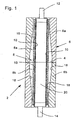
- Figures 1 to 3 show schematic representations of three different embodiments of the device according to the invention, respectively in longitudinal section
- Fig. 4 shows the principle of a multiple arrangement of the device according to the invention, in cross section.
- the device 2 shown in longitudinal section in Fig. 1 consists of a two-part, in the parting line 4 axially divided outer double mold 6, with an "upper” 6a and a “lower” mold half 6b.
- the tool halves 6a, 6b are heated, preferably electric.
- Each mold half 6a, 6b each has an approximately bottle-shaped Cavity 8a, 8b, which are arranged in mirror image to each other, so that in the Center of the common cavity 8 results in a bulbous expansion.
- a heat-resistant elastomeric material preferably addition-crosslinked Silicon is made and clamped at its ends.
- Upper 12 and lower Clamping 14 are axially movable.
- hose roll section 16 of about twice Length of the finished product over the bladder (the heating jacket, 10) slipped.
- the vulcanization is carried out with the silicone bladder 10 from the inside without Vorblähen against the outer mold 6.
- the outer mold 6 is heated.
- the vulcanization process is completed and the bladder (the heating jacket) 10 is vented against the environment.
- the bladder (the Heating sleeve) 10 back to the original diameter.
- the vulcanized Doppelrollbalg 16 can be removed. Ie: it Two contiguous products are vulcanized in a single step. Subsequently, the mirror-image formed Doppelrollbalg 16 is divided in the middle, resulting in two equal rolling bellows.
- Fig. 2 In the construction shown in Fig. 2 is an "upper" clamping 12 'of the Bladder 10 via a piston rod 22 by a “lower” clamping 14 'out. Between the piston rod 22 and the “lower” clamping 14 'is a Slide bearing and a seal.
- This arrangement has the advantage that the Feeding of the blanks 16 and the discharge of Vulkanisate from one side undisturbed is possible.
- the supply of the pressure chamber 20 is via a central bore in the Piston rod 22 ensured.
- the "lower” clamping 14 'and the piston rod 22 are coupled via a pneumatic cylinder 24.
- the pressure chamber 26 of the pneumatic cylinder 24 is connected to the pressure chamber 20.
- the cylindrical surface of the piston 28 and the annular surface 30 of the "lower” clamping 14 ' are the same size. This ensures that the "lower” clamping 14 'for each Vulkanisationstik is guided axially free of force to the piston rod 22.
- the axial stroke of the pneumatic cylinder 24 is received via a suitable measuring device.
- the axial position of the piston rod 22 is controlled by a suitable linear unit so that the stroke of the piston rod 22 is always twice the stroke of the pneumatic cylinder 24. As a result, a symmetrical to the parting plane 4 indentation is achieved.
- the design has the advantage that the linear unit on the piston rod 22 only has to transmit small forces.
- Fig. 3 shows a further embodiment of the invention Vulcanizing.
- Both linear units are in opposite directions via a control as a function of vulcanization pressure so Driven that the mechanical load between cuff 10 and clamping 12 ", 14" gets small. Again, a symmetrical to the parting plane 4 indentation reached.
- FIG. 4 illustrated development of the device 2 according to the invention a so-called “Rundauerrloch” (“Rundêtr” 34) proposed.
- a stationary handling device 38 has a working area 40 on and allows the coating with blanks and the removal of each vulcanized products.
Landscapes
- Engineering & Computer Science (AREA)
- Mechanical Engineering (AREA)
- General Engineering & Computer Science (AREA)
- Manufacturing & Machinery (AREA)
- Heating, Cooling, Or Curing Plastics Or The Like In General (AREA)
- Moulds For Moulding Plastics Or The Like (AREA)
- Air Bags (AREA)
- Moulding By Coating Moulds (AREA)
- Rolls And Other Rotary Bodies (AREA)
- Diaphragms And Bellows (AREA)
Description
Die Erfindung beschäftigt sich mit dieser Ausformung und Vulkanisation der Schlauchrollbalg-Rohlinge.
Auch lässt die gestaltliche Präzision des aufzuweitenden Rohling-Endes zu wünschen übrig. In der Praxis hat sich gezeigt, dass die Einspann-Enden für die weitere Verwendung unbrauchbar sind und deshalb abgetrennt werden müssen, d. h. es gibt beidendig Verschnitt in nicht zu vernachlässigendem Ausmaß.
Deren grundsätzliche Vorteile bestehen außer in einem Verzicht auf Vorblähen (Kosten, Qualität) in einer Verminderung von Vulkanisationsfehlern. Durch das erfindungsgemäße Doppelrollbalg-Prinzip ergibt sich eine doppelte Produktivität. In der Mitte des Zwischenprodukts (Doppelrollbalg) gibt es keinen Verschnitt. Eine Automatisierbarkeit ist möglich.
Bevorzugte Ausgestaltungen und Weiterbildungen ergeben sich aus den Unteransprüchen.
Die Figuren 1 bis 3 zeigen Prinzipdarstellungen von drei verschiedenen Ausführungsformen der erfindungsgemäßen Vorrichtung, jeweils im Längsschnitt, und Fig. 4 zeigt das Prinzip einer Mehrfachanordnung der erfindungsgemäßen Vorrichtung, im Querschnitt.
Durch den Aufweitvorgang verkürzt sich der Luftfeder-Rohling 16 konstruktionsbedingt axial. Die axiale Verkürzung überträgt sich durch Reibung auf den Heizbalg 10 und führt zu einer hohen mechanischen Belastung des Heizbalges 10, vor allem an den beiden Einspannnungen 12, 14. Dieses Problem wird erfindungsgemäß so gelöst, dass die axial beweglichen Einspannungen 12, 14 des Heizbalgs 10 während der Aufweitung und der damit verbundenen axialen Verkürzung dergestalt nachgeführt werden, dass die mechanische Belastung des Heizbalgs 10 klein wird.
Der axiale Hub des Pneumatikzylinders 24 wird über eine geeignete Messvorrichtung aufgenommen. Die axiale Position der Kolbenstange 22 wird über eine geeignete Lineareinheit so gesteuert, dass der Hub der Kolbenstange 22 stets das doppelte des Hubes des Pneumatikzylinders 24 beträgt. Hierdurch wird eine zur Trennebene 4 symmetrische Einformung erreicht.
Die Ausführung weist den Vorteil auf, dass die Lineareinheit an der Kolbenstange 22 nur kleine Kräfte übertragen muss.
- 2, 2a, 2b, ...
- Vorrichtung, Vulkanisationsvorrichtung
- 4
- Trennebene
- 6
- Außendoppelform, Doppelform, Außenform
- 6a
- "obere" Werkzeughälfte
- 6b
- "untere" Werkzeughälfte
- 8a
- flaschenförmiger Hohlraum der "oberen" Werkzeughälfte
- 8b
- flaschenförmiger Hohlraum der "unteren" Werkzeughälfte
- 10
- Heizbalg, Heizmanschette, Manschette, Silicon-Heizbalg
- 12, 12', 12"
- "obere" Einspannung
- 14, 14', 14"
- "untere" Einspannung
- 16
- Schlauchrollbalg-Abschnitt, Rohling, Schlauchrollbalg-Rohling, Luftfeder-Rohling, Doppelrollbalg
- 18
- Werkzeugwandung, innere Wandung der Außenform
- 20
- Druckraum
- 22, 22'
- Kolbenstange
- 24
- Pneumatikzylinder
- 26
- Druckraum des Pneumatikzylinders
- 28
- Kolben
- 30
- Kreisringfläche
- 32
- weitere Kolbenstange
- 34
- Trommel
- 38
- Handhabungseinrichtung
- 40
- Arbeitsbereich
Claims (14)
- Verfahren zur Ausformung von Luftfeder-Schlauchrollbälgen,
dadurch gekennzeichnet,dass ein Schlauchrollbalg-Abschnitt (Schlauchrollbalg-Rohling, 16) von etwa der doppelten Länge des fertigen Produktes über einen Heizbalg (eine Heizmanschette, 10) geführt wird,dass Druckluft in den innerhalb des Heizbalgs (10) befindlichen Druckraum (20) gedrückt wird, wodurch sich der aus Silicon bestehende Heizbalg (10) aufbläht und den Schlauchrollbalg-Rohling (16) gegen die bauchige innere Wandung (18) einer Außenform (6) drückt, wodurch sich der Luftfeder-Rohling (16) durch den Aufweitvorgang konstruktionsbedingt axial verkürzt, unddass endseitige, axial bewegliche Einspannungen (12, 14; 12', 14' oder 12", 14") des Heizbalgs (10) während der Aufweitung und der damit verbundenen axialen Verkürzung axial dergestalt nachgeführt werden, dass die mechanische Belastung des Heizbalgs (10) klein bleibt. - Verfahren nach Anspruch 1,
dadurch gekennzeichnet,dass eine obere Einspannung (12") der Heizmanschette (10) über eine durch eine untere Einspannung (14") verlaufende Kolbenstange (22') geführt wird, und mit einer geeigneten Lineareinheit verbunden ist,dass die untere Einspannung (14") über eine weitere Kolbenstange (32) ebenfalls mit einer Lineareinheit verbunden ist, unddass beide Lineareinheiten über eine Steuerung gegensinnig als Funktion des Vulkanisationsdruckes so geführt werden, dass die mechanische Belastung zwischen Heizbalg (10) und Einspannung (12", 14") klein bleibt. - Verfahren nach Anspruch 1 oder 2,
dadurch gekennzeichnet, dass die Vulkanisation mit dem Heizbalg (10) von innen ohne Vorblähen gegen die Außenform (6) erfolgt,
wobei die Außenform (6) während der Vulkanisationszeit beheizt ist. - Verfahren nach einem der Ansprüche 1 bis 3,
dadurch gekennzeichnet, dass der ausvulkanisierte Doppelrollbalg (16) nach Öffnen der Außenform (6) entnommen wird. - Verfahren nach einem der Ansprüche 1 bis 4,
dadurch gekennzeichnet, dass der spiegelbildlich ausgebildete Doppelrollbalg (16) mittig zerteilt wird, wodurch zwei gleichgroße Rollbälge entstehen. - Verfahren nach einem der Ansprüche 1 bis 5,
dadurch gekennzeichnet, dass die Versorgung des Druckraumes (20) über eine zentrale Bohrung in einer die Einspannungen (12', 14' oder 12", 14") verbindende Kolbenstange (22 oder 22') erfolgt. - Vorrichtung zur Durchführung des Verfahrens nach einem der Ansprüche 1 bis 6,
mit einer Außenform (6) und mit einem zylindrischen Heizbalg (10),
dadurch gekennzeichnet,wobei beide Werkzeughälften (6a, 6b) jeweils einen etwa flaschenförmigen Hohlraum (8a, 8b) aufweisen und spiegelbildlich zueinander angeordnet sind, so dass sich in der Mitte des gemeinsamen Hohlraums (8) eine bauchige Aufweitung (8) ergibt, unddass die Außenform (6) in einer Trennebene (4) in eine obere (6a) sowie eine unteren Werkzeughälfte (6b) geteilt ist,dass sich der Heizbalg (10) im Innern der Doppelform (6) axial erstreckt, etwa die Länge eines zu vulkanisierenden Doppelrollbalgs (16) aufweist, und dessen Enden in eine oberen (12, 12' oder 12") und in eine untere Einspannung (14, 14' oder 14") axial beweglich eingespannt sind. - Vorrichtung nach Anspruch 7,
dadurch gekennzeichnet, dass die obere Einspannung (12') des Heizbalgs (10) über eine Kolbenstange (22) mit einer unteren Einspannung (14') axial beweglich verbunden ist,
wobei sich zwischen der Kolbenstange (22) und der unteren Einspannung (14') ein Gleitlager sowie eine Dichtung befindet. - Vorrichtung nach Anspruch 8,
dadurch gekennzeichnet, dass die untere Einspannung (14') sowie die Kolbenstange (22) über einen Pneumatikzylinder (24) gekoppelt sind, und dass der Druckraum (26) des Pneumatikzylinders (24) mit dem Druckraum (20) des Heizbalgs (10) verbunden ist,
wobei die Zylinderfläche des Kolbens (28) und die Kreisringfläche (30) der unteren Einspannung (14') gleichgroß sind. - Vorrichtung nach Anspruch 7 oder 8,
dadurch gekennzeichnet, dass der Hub der Kolbenstange (22) stets das doppelte des Hubs des Pneumatikzylinders (24) beträgt. - Vorrichtung nach Anspruch 7,
dadurch gekennzeichnet,dass eine obere Einspannung (12") der Heizmanschette (10) über eine Kolbenstange (22') durch eine untere Einspannung (14") geführt und mit einer Lineareinheit verbunden ist, unddass die untere Einspannung (14") über eine weitere Kolbenstange (32) ebenfalls mit einer Lineareinheit verbunden ist. - Vorrichtung nach einem der Ansprüche 7 bis 11,
dadurch gekennzeichnet, dass die Werkzeughälften (6a, 6b) elektrisch beheizbar sind. - Vorrichtung nach einem der Ansprüche 7 bis 12,
dadurch gekennzeichnet, dass der Heizbalg (10) etwa die Länge eines auszuformenden Schlauchrollbalg-Abschnittes (16) aufweist und aus einem wärmebeständigen elastomeren Werkstoff besteht. - Vorrichtung nach einem der Ansprüch 7 bis 13,
gekennzeichnet durch
einen Rundläufer (34),wobei mehrere Vulkanisationsvorrichtungen (2a, 2b, ...) auf einer Trommel (36) drehbar angeordnet sind, undwobei eine Handhabungseinrichtung (38) mit einem Arbeitsbereich (40) das Beschichten mit Rohlingen (16) und die Entnahme der jeweils ausvulkanisierten Produkte ermöglicht.
Applications Claiming Priority (2)
| Application Number | Priority Date | Filing Date | Title |
|---|---|---|---|
| DE10247337A DE10247337B3 (de) | 2002-10-10 | 2002-10-10 | Ausformung von Luftfeder-Schlauchrollbälgen |
| DE10247337 | 2002-10-10 |
Publications (2)
| Publication Number | Publication Date |
|---|---|
| EP1407875A1 EP1407875A1 (de) | 2004-04-14 |
| EP1407875B1 true EP1407875B1 (de) | 2005-11-23 |
Family
ID=32010427
Family Applications (1)
| Application Number | Title | Priority Date | Filing Date |
|---|---|---|---|
| EP03019825A Expired - Lifetime EP1407875B1 (de) | 2002-10-10 | 2003-08-30 | Ausformung von Luftfeder-Schlauchrollbälgen |
Country Status (7)
| Country | Link |
|---|---|
| US (2) | US7001553B2 (de) |
| EP (1) | EP1407875B1 (de) |
| KR (1) | KR101086195B1 (de) |
| CN (1) | CN100418723C (de) |
| AT (1) | ATE310635T1 (de) |
| DE (2) | DE10247337B3 (de) |
| MX (1) | MXPA03008748A (de) |
Cited By (2)
| Publication number | Priority date | Publication date | Assignee | Title |
|---|---|---|---|---|
| DE102007052738A1 (de) | 2007-11-06 | 2009-05-07 | Continental Aktiengesellschaft | Verfahren zum Herstellen bombierter, schlauchförmiger Erzeugnisse |
| DE102013211641A1 (de) * | 2013-06-20 | 2014-12-24 | Continental Teves Ag & Co. Ohg | Verfahren zum Aufweiten eines Luftfederbalg-Rohlings sowie Vorrichtung zur Durchführung des Verfahrens |
Families Citing this family (12)
| Publication number | Priority date | Publication date | Assignee | Title |
|---|---|---|---|---|
| DE10247337B3 (de) | 2002-10-10 | 2004-04-29 | Contitech Luftfedersysteme Gmbh | Ausformung von Luftfeder-Schlauchrollbälgen |
| CN101503002B (zh) * | 2009-03-11 | 2011-03-16 | 宁波美亚达汽车部件制造有限公司 | 空气弹簧压装机 |
| CN101987437B (zh) * | 2009-07-30 | 2012-12-26 | 中国商用飞机有限责任公司 | 一种气囊夹紧装置 |
| CN102029969B (zh) * | 2009-09-29 | 2013-05-15 | 丰田合成株式会社 | 树脂气囊 |
| KR100959364B1 (ko) * | 2009-12-30 | 2010-05-24 | 선진정밀(주) | 에어 현가장치의 스프링튜브 융착기 |
| EP2796747A4 (de) * | 2011-12-20 | 2015-09-30 | Bridgestone Corp | Luftfeder |
| CN102555042A (zh) * | 2012-02-23 | 2012-07-11 | 彭代汉 | 一种石膏空心砌块的模具芯棒 |
| DE102017206655B4 (de) * | 2017-04-20 | 2020-07-09 | Contitech Luftfedersysteme Gmbh | Einrichtung zum Vulkanisieren eines Rohlings aus elastomerem Material |
| CN107280851B (zh) * | 2017-06-21 | 2019-09-06 | 周浩然 | 一种可循环使用的硅胶发热袋的制备方法及应用 |
| CN111802770A (zh) * | 2020-08-13 | 2020-10-23 | 哈尔滨工业大学 | 一种可折叠行李箱 |
| CN113232131A (zh) * | 2021-05-14 | 2021-08-10 | 西安市红会医院 | 一种腱病动物模型构建用骨水泥块的浇筑模具 |
| CN115091734B (zh) * | 2022-05-13 | 2024-05-10 | 广东省科学院生物与医学工程研究所 | 波形流道聚合物毛细管制备方法及波形流道聚合物毛细管 |
Family Cites Families (11)
| Publication number | Priority date | Publication date | Assignee | Title |
|---|---|---|---|---|
| BE420828A (de) * | ||||
| CH211702A (de) * | 1938-05-17 | 1940-10-15 | Firestone Tire & Rubber Co | Vorrichtung zum Formen hohler, dehnbarer Körper. |
| US3057768A (en) * | 1957-01-07 | 1962-10-09 | Firestone Tire & Rubber Co | Method of forming an air spring of rubberized fabric plies |
| DE1120677B (de) * | 1957-01-07 | 1961-12-28 | Firestone Tire & Rubber Co | Verfahren und Einrichtung zum Verformen eines Balgrohlings fuer den Federkoerper einer Luftfeder |
| GB1069782A (en) * | 1963-03-23 | 1967-05-24 | Dunlop Rubber Co | Flexible diaphragms and methods and apparatus for the manufacture thereof |
| FR1386115A (fr) * | 1964-03-23 | 1965-01-15 | Dunlop Rubber Co | Procédé de fabrication de diaphragmes flexibles, appareil utilisé et produits obtenus |
| US3651180A (en) * | 1968-08-08 | 1972-03-21 | Foam Forms Inc | Method of molding expandable polystyrene particles using an inflatable core in the mold cavity |
| US4017572A (en) * | 1974-02-04 | 1977-04-12 | The Upjohn Company | Method of molding articles of polymeric foam substantially free from flashing |
| US4673168A (en) * | 1985-06-25 | 1987-06-16 | The Goodyear Tire & Rubber Company | Airspring and a method for making airspring flexible members |
| US5382006A (en) * | 1993-09-29 | 1995-01-17 | The Goodyear Tire & Rubber Company | Airspring piston and airspring assembly |
| DE10247337B3 (de) | 2002-10-10 | 2004-04-29 | Contitech Luftfedersysteme Gmbh | Ausformung von Luftfeder-Schlauchrollbälgen |
-
2002
- 2002-10-10 DE DE10247337A patent/DE10247337B3/de not_active Expired - Fee Related
-
2003
- 2003-08-30 DE DE50301726T patent/DE50301726D1/de not_active Expired - Lifetime
- 2003-08-30 AT AT03019825T patent/ATE310635T1/de not_active IP Right Cessation
- 2003-08-30 EP EP03019825A patent/EP1407875B1/de not_active Expired - Lifetime
- 2003-09-26 MX MXPA03008748A patent/MXPA03008748A/es active IP Right Grant
- 2003-10-09 KR KR1020030070290A patent/KR101086195B1/ko not_active Expired - Fee Related
- 2003-10-10 US US10/682,577 patent/US7001553B2/en not_active Expired - Lifetime
- 2003-10-10 CN CNB2003101006401A patent/CN100418723C/zh not_active Expired - Fee Related
-
2005
- 2005-09-28 US US11/236,530 patent/US7361007B2/en not_active Expired - Fee Related
Cited By (3)
| Publication number | Priority date | Publication date | Assignee | Title |
|---|---|---|---|---|
| DE102007052738A1 (de) | 2007-11-06 | 2009-05-07 | Continental Aktiengesellschaft | Verfahren zum Herstellen bombierter, schlauchförmiger Erzeugnisse |
| EP2058113A2 (de) | 2007-11-06 | 2009-05-13 | Continental Aktiengesellschaft | Verfahren zum Herstellen bombierter, schlauchförmiger Erzeugnisse |
| DE102013211641A1 (de) * | 2013-06-20 | 2014-12-24 | Continental Teves Ag & Co. Ohg | Verfahren zum Aufweiten eines Luftfederbalg-Rohlings sowie Vorrichtung zur Durchführung des Verfahrens |
Also Published As
| Publication number | Publication date |
|---|---|
| US20040084135A1 (en) | 2004-05-06 |
| CN1496804A (zh) | 2004-05-19 |
| ATE310635T1 (de) | 2005-12-15 |
| US7001553B2 (en) | 2006-02-21 |
| DE10247337B3 (de) | 2004-04-29 |
| KR20040032788A (ko) | 2004-04-17 |
| MXPA03008748A (es) | 2004-09-10 |
| US20060021707A1 (en) | 2006-02-02 |
| CN100418723C (zh) | 2008-09-17 |
| US7361007B2 (en) | 2008-04-22 |
| KR101086195B1 (ko) | 2011-11-25 |
| EP1407875A1 (de) | 2004-04-14 |
| DE50301726D1 (de) | 2005-12-29 |
Similar Documents
| Publication | Publication Date | Title |
|---|---|---|
| DE2301286C2 (de) | Vorrichtung zum Herstellen eines Rohlings für Luftreifen | |
| EP1407875A1 (de) | Ausformung von Luftfeder-Schlauchrollbälgen | |
| EP0629456B1 (de) | Vorrichtung zum Herstellen von Hohlkörpern | |
| DE112008003059T5 (de) | Verfahren zur Herstellung von verstärktem Gummi-Schlauch | |
| DE69706286T2 (de) | Verfahren und vorrichtung zum herstellen von behältern aus kunststoff | |
| DE2243458A1 (de) | Verfahren und vorrichtung fuer die erneuerung von reifen-laufflaechen | |
| EP0885711B1 (de) | Extrusionskopf für eine Anlage zum Extrusionsblasformen von Höhlkörpern, insbesondere Kunststoff-Kraftstoffbehälter | |
| DE2234162A1 (de) | Verfahren und vorrichtung zum herstellen eines pneumatischen luftreifens | |
| DE2758188A1 (de) | Verfahren und vorrichtung zum bilden einer inneren ringnut in einem kunststoffrohrteil | |
| DE2162311A1 (de) | Vorrichtung zum herstellen von luftreifen | |
| DE3030832A1 (de) | Einrichtung fuer die herstellung von luftreifen | |
| DE3101284C2 (de) | Verfahren zum Formen des offenen Endabschnittes eines einen geschlossenen Boden aufweisenden Vorformlings für das Blasformen eines Hohlkörpers aus thermoplastischem Kunststoff, insbesondere einer Flasche, und Vorrichtung zum Durchführen des Verfahrens | |
| DE2161406A1 (de) | Vorrichtung zum herstellen von luftreifen | |
| DE4038077C2 (de) | ||
| DE69907117T2 (de) | Reifenvulkanisationsform | |
| DE4128548C2 (de) | Vorrichtung und Verfahren zum Vulkanisieren endloser Gummiriemen | |
| DE1068457B (de) | Reifen-Aufbautrommel | |
| DE2817099A1 (de) | Vorrichtung zum herstellen eines aus einem thermoplastischen kunststoff bestehenden rohrfoermigen koerpers | |
| EP1304202A1 (de) | Heizschlauchlose Fertigung von 3-Faltenbälgen | |
| DE10103257A1 (de) | Vulkanisiervorrichtung für Luftfeder-Rollbälge | |
| DE899107C (de) | Verfahren und Presse zum Bombieren und Vulkanisieren von Luftreifen | |
| EP1321284A1 (de) | Verfahren zur Herstellung eines vulkanisierten gekrümmten Schlauchs in einer Negativform unter Verwendung einer temporären Schlauchummantelung | |
| DE10302883B4 (de) | Vulkanisationsverfahren und Vulkanisationsvorrichtung mit Balg für PKW-Luftfedern | |
| DE102006058685A1 (de) | Verfahren zur Herstellung eines Fahrzeugluftreifens mit einem ortsbeweglichen Heizbalg und Vorrichtung zur Einformung des Heizbalges in den Reifenrohling | |
| EP3727780B1 (de) | Verfahren zur herstellung eines geformten hohlkörpers und vorrichtung zur durchführung des verfahrens |
Legal Events
| Date | Code | Title | Description |
|---|---|---|---|
| PUAI | Public reference made under article 153(3) epc to a published international application that has entered the european phase |
Free format text: ORIGINAL CODE: 0009012 |
|
| AK | Designated contracting states |
Kind code of ref document: A1 Designated state(s): AT BE BG CH CY CZ DE DK EE ES FI FR GB GR HU IE IT LI LU MC NL PT RO SE SI SK TR |
|
| AX | Request for extension of the european patent |
Extension state: AL LT LV MK |
|
| 17P | Request for examination filed |
Effective date: 20041014 |
|
| AKX | Designation fees paid |
Designated state(s): AT BE BG CH CY CZ DE DK EE ES FI FR GB GR HU IE IT LI LU MC NL PT RO SE SI SK TR |
|
| GRAP | Despatch of communication of intention to grant a patent |
Free format text: ORIGINAL CODE: EPIDOSNIGR1 |
|
| GRAS | Grant fee paid |
Free format text: ORIGINAL CODE: EPIDOSNIGR3 |
|
| GRAA | (expected) grant |
Free format text: ORIGINAL CODE: 0009210 |
|
| AK | Designated contracting states |
Kind code of ref document: B1 Designated state(s): AT BE BG CH CY CZ DE DK EE ES FI FR GB GR HU IE IT LI LU MC NL PT RO SE SI SK TR |
|
| PG25 | Lapsed in a contracting state [announced via postgrant information from national office to epo] |
Ref country code: NL Free format text: LAPSE BECAUSE OF FAILURE TO SUBMIT A TRANSLATION OF THE DESCRIPTION OR TO PAY THE FEE WITHIN THE PRESCRIBED TIME-LIMIT Effective date: 20051123 Ref country code: SK Free format text: LAPSE BECAUSE OF FAILURE TO SUBMIT A TRANSLATION OF THE DESCRIPTION OR TO PAY THE FEE WITHIN THE PRESCRIBED TIME-LIMIT Effective date: 20051123 Ref country code: FI Free format text: LAPSE BECAUSE OF FAILURE TO SUBMIT A TRANSLATION OF THE DESCRIPTION OR TO PAY THE FEE WITHIN THE PRESCRIBED TIME-LIMIT Effective date: 20051123 Ref country code: SI Free format text: LAPSE BECAUSE OF FAILURE TO SUBMIT A TRANSLATION OF THE DESCRIPTION OR TO PAY THE FEE WITHIN THE PRESCRIBED TIME-LIMIT Effective date: 20051123 Ref country code: RO Free format text: LAPSE BECAUSE OF FAILURE TO SUBMIT A TRANSLATION OF THE DESCRIPTION OR TO PAY THE FEE WITHIN THE PRESCRIBED TIME-LIMIT Effective date: 20051123 |
|
| REG | Reference to a national code |
Ref country code: GB Ref legal event code: FG4D Free format text: NOT ENGLISH |
|
| REG | Reference to a national code |
Ref country code: CH Ref legal event code: EP |
|
| REF | Corresponds to: |
Ref document number: 50301726 Country of ref document: DE Date of ref document: 20051229 Kind code of ref document: P |
|
| REG | Reference to a national code |
Ref country code: IE Ref legal event code: FG4D Free format text: LANGUAGE OF EP DOCUMENT: GERMAN |
|
| PG25 | Lapsed in a contracting state [announced via postgrant information from national office to epo] |
Ref country code: DK Free format text: LAPSE BECAUSE OF FAILURE TO SUBMIT A TRANSLATION OF THE DESCRIPTION OR TO PAY THE FEE WITHIN THE PRESCRIBED TIME-LIMIT Effective date: 20060223 Ref country code: BG Free format text: LAPSE BECAUSE OF FAILURE TO SUBMIT A TRANSLATION OF THE DESCRIPTION OR TO PAY THE FEE WITHIN THE PRESCRIBED TIME-LIMIT Effective date: 20060223 Ref country code: GR Free format text: LAPSE BECAUSE OF FAILURE TO SUBMIT A TRANSLATION OF THE DESCRIPTION OR TO PAY THE FEE WITHIN THE PRESCRIBED TIME-LIMIT Effective date: 20060223 |
|
| PG25 | Lapsed in a contracting state [announced via postgrant information from national office to epo] |
Ref country code: ES Free format text: LAPSE BECAUSE OF FAILURE TO SUBMIT A TRANSLATION OF THE DESCRIPTION OR TO PAY THE FEE WITHIN THE PRESCRIBED TIME-LIMIT Effective date: 20060306 |
|
| REG | Reference to a national code |
Ref country code: SE Ref legal event code: TRGR |
|
| GBT | Gb: translation of ep patent filed (gb section 77(6)(a)/1977) |
Effective date: 20060306 |
|
| PG25 | Lapsed in a contracting state [announced via postgrant information from national office to epo] |
Ref country code: PT Free format text: LAPSE BECAUSE OF FAILURE TO SUBMIT A TRANSLATION OF THE DESCRIPTION OR TO PAY THE FEE WITHIN THE PRESCRIBED TIME-LIMIT Effective date: 20060424 |
|
| REG | Reference to a national code |
Ref country code: HU Ref legal event code: AG4A Ref document number: E000237 Country of ref document: HU |
|
| NLV1 | Nl: lapsed or annulled due to failure to fulfill the requirements of art. 29p and 29m of the patents act | ||
| PG25 | Lapsed in a contracting state [announced via postgrant information from national office to epo] |
Ref country code: MC Free format text: LAPSE BECAUSE OF NON-PAYMENT OF DUE FEES Effective date: 20060831 Ref country code: BE Free format text: LAPSE BECAUSE OF NON-PAYMENT OF DUE FEES Effective date: 20060831 |
|
| PLBE | No opposition filed within time limit |
Free format text: ORIGINAL CODE: 0009261 |
|
| STAA | Information on the status of an ep patent application or granted ep patent |
Free format text: STATUS: NO OPPOSITION FILED WITHIN TIME LIMIT |
|
| PG25 | Lapsed in a contracting state [announced via postgrant information from national office to epo] |
Ref country code: FR Free format text: LAPSE BECAUSE OF FAILURE TO SUBMIT A TRANSLATION OF THE DESCRIPTION OR TO PAY THE FEE WITHIN THE PRESCRIBED TIME-LIMIT Effective date: 20061020 |
|
| 26N | No opposition filed |
Effective date: 20060824 |
|
| EN | Fr: translation not filed | ||
| PG25 | Lapsed in a contracting state [announced via postgrant information from national office to epo] |
Ref country code: AT Free format text: LAPSE BECAUSE OF NON-PAYMENT OF DUE FEES Effective date: 20060830 |
|
| BERE | Be: lapsed |
Owner name: CONTITECH LUFTFEDERSYSTEME G.M.B.H. Effective date: 20060831 |
|
| REG | Reference to a national code |
Ref country code: CH Ref legal event code: PL |
|
| PG25 | Lapsed in a contracting state [announced via postgrant information from national office to epo] |
Ref country code: CH Free format text: LAPSE BECAUSE OF NON-PAYMENT OF DUE FEES Effective date: 20070831 Ref country code: LI Free format text: LAPSE BECAUSE OF NON-PAYMENT OF DUE FEES Effective date: 20070831 |
|
| PG25 | Lapsed in a contracting state [announced via postgrant information from national office to epo] |
Ref country code: EE Free format text: LAPSE BECAUSE OF FAILURE TO SUBMIT A TRANSLATION OF THE DESCRIPTION OR TO PAY THE FEE WITHIN THE PRESCRIBED TIME-LIMIT Effective date: 20051123 |
|
| PG25 | Lapsed in a contracting state [announced via postgrant information from national office to epo] |
Ref country code: LU Free format text: LAPSE BECAUSE OF NON-PAYMENT OF DUE FEES Effective date: 20060830 |
|
| PG25 | Lapsed in a contracting state [announced via postgrant information from national office to epo] |
Ref country code: FR Free format text: LAPSE BECAUSE OF FAILURE TO SUBMIT A TRANSLATION OF THE DESCRIPTION OR TO PAY THE FEE WITHIN THE PRESCRIBED TIME-LIMIT Effective date: 20051123 Ref country code: CY Free format text: LAPSE BECAUSE OF FAILURE TO SUBMIT A TRANSLATION OF THE DESCRIPTION OR TO PAY THE FEE WITHIN THE PRESCRIBED TIME-LIMIT Effective date: 20051123 |
|
| PGFP | Annual fee paid to national office [announced via postgrant information from national office to epo] |
Ref country code: CZ Payment date: 20140822 Year of fee payment: 12 Ref country code: IE Payment date: 20140828 Year of fee payment: 12 |
|
| PGFP | Annual fee paid to national office [announced via postgrant information from national office to epo] |
Ref country code: SE Payment date: 20140820 Year of fee payment: 12 Ref country code: HU Payment date: 20140821 Year of fee payment: 12 Ref country code: GB Payment date: 20140820 Year of fee payment: 12 |
|
| REG | Reference to a national code |
Ref country code: SE Ref legal event code: EUG |
|
| GBPC | Gb: european patent ceased through non-payment of renewal fee |
Effective date: 20150830 |
|
| PG25 | Lapsed in a contracting state [announced via postgrant information from national office to epo] |
Ref country code: CZ Free format text: LAPSE BECAUSE OF NON-PAYMENT OF DUE FEES Effective date: 20150830 |
|
| PG25 | Lapsed in a contracting state [announced via postgrant information from national office to epo] |
Ref country code: HU Free format text: LAPSE BECAUSE OF NON-PAYMENT OF DUE FEES Effective date: 20150831 Ref country code: SE Free format text: LAPSE BECAUSE OF NON-PAYMENT OF DUE FEES Effective date: 20150831 |
|
| REG | Reference to a national code |
Ref country code: IE Ref legal event code: MM4A |
|
| PG25 | Lapsed in a contracting state [announced via postgrant information from national office to epo] |
Ref country code: IE Free format text: LAPSE BECAUSE OF NON-PAYMENT OF DUE FEES Effective date: 20150830 Ref country code: GB Free format text: LAPSE BECAUSE OF NON-PAYMENT OF DUE FEES Effective date: 20150830 |
|
| PGFP | Annual fee paid to national office [announced via postgrant information from national office to epo] |
Ref country code: IT Payment date: 20160825 Year of fee payment: 14 |
|
| PG25 | Lapsed in a contracting state [announced via postgrant information from national office to epo] |
Ref country code: IT Free format text: LAPSE BECAUSE OF NON-PAYMENT OF DUE FEES Effective date: 20170830 |
|
| PGFP | Annual fee paid to national office [announced via postgrant information from national office to epo] |
Ref country code: DE Payment date: 20180831 Year of fee payment: 16 |
|
| PGFP | Annual fee paid to national office [announced via postgrant information from national office to epo] |
Ref country code: TR Payment date: 20190819 Year of fee payment: 17 |
|
| REG | Reference to a national code |
Ref country code: DE Ref legal event code: R119 Ref document number: 50301726 Country of ref document: DE |
|
| PG25 | Lapsed in a contracting state [announced via postgrant information from national office to epo] |
Ref country code: DE Free format text: LAPSE BECAUSE OF NON-PAYMENT OF DUE FEES Effective date: 20200303 |
|
| PG25 | Lapsed in a contracting state [announced via postgrant information from national office to epo] |
Ref country code: TR Free format text: LAPSE BECAUSE OF NON-PAYMENT OF DUE FEES Effective date: 20200830 |