EP1407232B1 - Komponent mit filter - Google Patents
Komponent mit filter Download PDFInfo
- Publication number
- EP1407232B1 EP1407232B1 EP02729351.3A EP02729351A EP1407232B1 EP 1407232 B1 EP1407232 B1 EP 1407232B1 EP 02729351 A EP02729351 A EP 02729351A EP 1407232 B1 EP1407232 B1 EP 1407232B1
- Authority
- EP
- European Patent Office
- Prior art keywords
- support member
- component
- filter
- housing
- over
- Prior art date
- Legal status (The legal status is an assumption and is not a legal conclusion. Google has not performed a legal analysis and makes no representation as to the accuracy of the status listed.)
- Expired - Lifetime
Links
Images




Classifications
-
- G—PHYSICS
- G01—MEASURING; TESTING
- G01L—MEASURING FORCE, STRESS, TORQUE, WORK, MECHANICAL POWER, MECHANICAL EFFICIENCY, OR FLUID PRESSURE
- G01L19/00—Details of, or accessories for, apparatus for measuring steady or quasi-steady pressure of a fluent medium insofar as such details or accessories are not special to particular types of pressure gauges
- G01L19/06—Means for preventing overload or deleterious influence of the measured medium on the measuring device or vice versa
- G01L19/0627—Protection against aggressive medium in general
- G01L19/0636—Protection against aggressive medium in general using particle filters
-
- G—PHYSICS
- G01—MEASURING; TESTING
- G01D—MEASURING NOT SPECIALLY ADAPTED FOR A SPECIFIC VARIABLE; ARRANGEMENTS FOR MEASURING TWO OR MORE VARIABLES NOT COVERED IN A SINGLE OTHER SUBCLASS; TARIFF METERING APPARATUS; MEASURING OR TESTING NOT OTHERWISE PROVIDED FOR
- G01D11/00—Component parts of measuring arrangements not specially adapted for a specific variable
- G01D11/24—Housings ; Casings for instruments
- G01D11/245—Housings for sensors
-
- G—PHYSICS
- G01—MEASURING; TESTING
- G01L—MEASURING FORCE, STRESS, TORQUE, WORK, MECHANICAL POWER, MECHANICAL EFFICIENCY, OR FLUID PRESSURE
- G01L19/00—Details of, or accessories for, apparatus for measuring steady or quasi-steady pressure of a fluent medium insofar as such details or accessories are not special to particular types of pressure gauges
- G01L19/14—Housings
- G01L19/141—Monolithic housings, e.g. molded or one-piece housings
-
- H—ELECTRICITY
- H10—SEMICONDUCTOR DEVICES; ELECTRIC SOLID-STATE DEVICES NOT OTHERWISE PROVIDED FOR
- H10W—GENERIC PACKAGES, INTERCONNECTIONS, CONNECTORS OR OTHER CONSTRUCTIONAL DETAILS OF DEVICES COVERED BY CLASS H10
- H10W72/00—Interconnections or connectors in packages
- H10W72/50—Bond wires
- H10W72/541—Dispositions of bond wires
- H10W72/547—Dispositions of multiple bond wires
- H10W72/5473—Dispositions of multiple bond wires multiple bond wires connected to a common bond pad
-
- H—ELECTRICITY
- H10—SEMICONDUCTOR DEVICES; ELECTRIC SOLID-STATE DEVICES NOT OTHERWISE PROVIDED FOR
- H10W—GENERIC PACKAGES, INTERCONNECTIONS, CONNECTORS OR OTHER CONSTRUCTIONAL DETAILS OF DEVICES COVERED BY CLASS H10
- H10W72/00—Interconnections or connectors in packages
- H10W72/851—Dispositions of multiple connectors or interconnections
- H10W72/874—On different surfaces
- H10W72/884—Die-attach connectors and bond wires
-
- H—ELECTRICITY
- H10—SEMICONDUCTOR DEVICES; ELECTRIC SOLID-STATE DEVICES NOT OTHERWISE PROVIDED FOR
- H10W—GENERIC PACKAGES, INTERCONNECTIONS, CONNECTORS OR OTHER CONSTRUCTIONAL DETAILS OF DEVICES COVERED BY CLASS H10
- H10W90/00—Package configurations
- H10W90/701—Package configurations characterised by the relative positions of pads or connectors relative to package parts
- H10W90/731—Package configurations characterised by the relative positions of pads or connectors relative to package parts of die-attach connectors
- H10W90/734—Package configurations characterised by the relative positions of pads or connectors relative to package parts of die-attach connectors between a chip and a stacked insulating package substrate, interposer or RDL
-
- H—ELECTRICITY
- H10—SEMICONDUCTOR DEVICES; ELECTRIC SOLID-STATE DEVICES NOT OTHERWISE PROVIDED FOR
- H10W—GENERIC PACKAGES, INTERCONNECTIONS, CONNECTORS OR OTHER CONSTRUCTIONAL DETAILS OF DEVICES COVERED BY CLASS H10
- H10W90/00—Package configurations
- H10W90/701—Package configurations characterised by the relative positions of pads or connectors relative to package parts
- H10W90/751—Package configurations characterised by the relative positions of pads or connectors relative to package parts of bond wires
- H10W90/753—Package configurations characterised by the relative positions of pads or connectors relative to package parts of bond wires between laterally-adjacent chips
-
- H—ELECTRICITY
- H10—SEMICONDUCTOR DEVICES; ELECTRIC SOLID-STATE DEVICES NOT OTHERWISE PROVIDED FOR
- H10W—GENERIC PACKAGES, INTERCONNECTIONS, CONNECTORS OR OTHER CONSTRUCTIONAL DETAILS OF DEVICES COVERED BY CLASS H10
- H10W90/00—Package configurations
- H10W90/701—Package configurations characterised by the relative positions of pads or connectors relative to package parts
- H10W90/751—Package configurations characterised by the relative positions of pads or connectors relative to package parts of bond wires
- H10W90/756—Package configurations characterised by the relative positions of pads or connectors relative to package parts of bond wires between a chip and a stacked lead frame, conducting package substrate or heat sink
-
- Y—GENERAL TAGGING OF NEW TECHNOLOGICAL DEVELOPMENTS; GENERAL TAGGING OF CROSS-SECTIONAL TECHNOLOGIES SPANNING OVER SEVERAL SECTIONS OF THE IPC; TECHNICAL SUBJECTS COVERED BY FORMER USPC CROSS-REFERENCE ART COLLECTIONS [XRACs] AND DIGESTS
- Y10—TECHNICAL SUBJECTS COVERED BY FORMER USPC
- Y10T—TECHNICAL SUBJECTS COVERED BY FORMER US CLASSIFICATION
- Y10T29/00—Metal working
- Y10T29/49—Method of mechanical manufacture
- Y10T29/49002—Electrical device making
- Y10T29/49007—Indicating transducer
Definitions
- This invention relates to filters, in general, and to components having filters and their methods of manufacture and operation, in particular.
- Physical sensor components such as, for example, pressure sensors can be used in automotive, industrial, consumer, and various other applications.
- Elastic gels, polymers, diaphragms, membranes, and other coatings or encapsulants have been used to protect the pressure sensors from the potentially corrosive environments in which the pressure sensors operate.
- none of these encapsulants are entirely impermeable to the corrosive environments.
- the encapsulants do not completely satisfy many stringent reliability requirements demanded by customers who use the pressure sensors.
- a common failure mechanism for a silicon pressure sensor having a prior art coating or encapsulant occurs due to diffusion of the corrosive media through the encapsulant, which delaminates the encapsulant from the silicon pressure sensor. This delamination exposes portions of the silicon pressure sensor that subsequently corrode from the direct exposure to the corrosive media.
- top, bottom, over, under, and the like in the description and in the claims, if any, are used for descriptive purposes and not necessarily for describing permanent relative positions. It is understood that the terms so used are interchangeable under appropriate circumstances such that the embodiments of the invention described herein are, for example, capable of operation in other orientations than illustrated or otherwise described herein.
- a component in accordance with the invention can comprise a sensor element and a filter that limits communication between the sensor element inside the component and a hostile environment outside the component.
- the filter can block potentially corrosive elements or media from the exterior environment while still permitting the unhindered transmission of pressure from the exterior environment to the sensor element inside the component.
- the component can be used in pressure sensing applications such as a tire pressure monitor.
- the component can be wheel-mounted, rim-mounted, tire-valve mounted, or tire-mounted.
- suitable applications for this component include gas, vapor, and other chemical monitors.
- Further examples of suitable applications for this component include medical and other biological monitors for pressure, liquid height, or flow rate measurements.
- FIG. 1 illustrates a top view of a component 100 having a cavity in communication with an environment outside component 100
- FIG. 2 illustrates a cross-sectional view of component 100 taken along a section line 2-2 in FIG. 1
- Component 100 comprises a package, chip carrier, or housing 110.
- housing 110 has a recess 115 and a cavity 125 located within recess 115. Housing 110 at least partially defines a lower portion of recess 115 and cavity 125. Housing 110 can include inserts or the like to define the actual boundaries of recess 115 and/or cavity 125.
- Housing 110 can also have a shelf or rim 120 located at a perimeter of recess 115. As explained in more detail hereinafter, rim 120 can be used to support two support members and a filter over cavity 125. Rim 120 is preferably continuous around the perimeter of recess 115 and can be located at an edge of cavity 125 or above cavity 125. Rim 120 comprises a surface 121 and comprises a plurality of protrusions 122 extending from surface 121. In the embodiment illustrated in FIG. 2 , surface 121 faces away from cavity 125, and protrusions 122 extend away from cavity 125. After understanding the embodiment illustrated in FIG. 2 , other embodiments of surface 121 and protrusions 122 will be obvious to those skilled in the art. Examples of other embodiments include, but are not limited to, different numbers of protrusions and different angles for the surface and for the protrusions.
- Housing 110 can further comprise an additional rim 130 located at a perimeter of cavity 125.
- Rim 130 is located below rim 120 within recess 115. As explained in more detailed hereinafter, rim 130 can be used to support electrical leads.
- Housing 110 can still further comprise a mounting surface 111 located in cavity 125.
- Mounting surface 111 is located below rim 130. As explained in more detailed hereinafter, mounting surface 111 can be used to support a sensor element and an electronic element.
- Housing 110 is preferably comprised of a substantially rigid material that is resistant to corrosion by the corrosive elements or media in the environment in which component 100 is used.
- housing 110 can be comprised of a PolyPhenyleneSulfide (PPS) material.
- PPS PolyPhenyleneSulfide
- Component 100 also comprises a sensor element 105.
- Sensor element 105 senses a characteristic of the environment outside of component 100 in which component 100 is used.
- the characteristic can be a pressure of the exterior environment.
- Sensor element 105 is located in cavity 125 of housing 110 and can be supported by mounting surface 111 of housing 110.
- Component 100 can further comprise an optional electronic element 106.
- Electronic element 106 can be used to control sensor element 105.
- electronic element 106 can monitor and/or store an output of sensor element 105.
- electronic element 106 can be a semiconductor element such as, for example, a single transistor or an integrated circuit. In one embodiment of component 100, electronic element 106 is not present in component 100.
- Electronic element 106 is located in cavity 125 of housing 110 and can be supported by mounting surface 111 of housing 110. Electronic element 106 is located adjacent to sensor element 105 and can be electrically coupled to sensor element 105. When component 100 includes electronic element 106, component 100 can be referred to as a module.
- Component 100 can further comprise an adhesive 107.
- Adhesive 107 couples sensor element 105 to mounting surface 111 of housing 110.
- a different portion of adhesive 107 can also be used to couple electronic element 106 to mounting surface 111 of housing 110.
- Component 100 can still further comprise electrical leads 101.
- a first portion of electrical leads 101 can protrude outside of housing 110.
- a second portion of electrical leads 101 can extend through housing 110.
- a third portion of electrical leads 101 can be located in cavity 125 and are supported by rim 130.
- the third portion of electrical leads 101 can be located below rim 120 and above mounting surface 111, and the third portion of electrical leads 101 can be electrically coupled to sensor element 105 and electronic element 106.
- the electrical coupling schemes between sensor element 105 and electrical leads 101, between electronic element 106 and electrical leads 101, and between sensor element 105 and electronic element 106 can be identical or different from each other and can include, for example, wire bonding, tape bonding, and/or flip chip bonding.
- Component 100 can additionally comprise a sealant or adhesive 135.
- adhesive 135 forms a continuous bead over rim 120 and around the perimeter of recess 115.
- adhesive 135 is a perfluoroether or other suitable material that is resistant to corrosion by the corrosive elements in the environment in which component 100 is used.
- suitable perfluoroether materials include Sifel 603 and 604, which are commercially available from Shin-Etsu Silicones of America, Inc. of Akron, Ohio, and RTV 8012, which is commercially available from Dow Corning Corporation of Auburn, Michigan. Sifel 603 and 604 are preferred over RTV 8012 because of their lower viscosity.
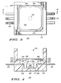
- FIG. 3 illustrates a top view of component 100 after additional manufacturing steps
- FIG. 4 illustrates a cross-sectional view of component 100 taken along a section line 4-4 in FIG. 3
- component 100 comprises a support member 340.
- support member 340 can improve the mechanical support, stability, and reliability for a filter in component 100.
- Support member 340 is located over at least a portion of housing 110 and over cavity 125. Support member 340 is also located within recess 115 of housing 110. For reasons explained hereinafter, the length and width of support member 340 is preferably slightly smaller than the length and width of recess 115.
- Support member 340 can have sides 342 and 343 and an edge 344 coupling together sides 342 and 343.
- Side 342 faces towards cavity 125, and side 343 faces away from cavity 125.
- Side 342 of support member 340 preferably at least partially defines an upper portion or boundary of cavity 125.
- Rim 120 supports support member 340 over cavity 125.
- protrusions 122 of rim 120 support side 342 of support member 340 over surface 121 of rim 120 and over cavity 125.
- Support member 340 has a hole 341 over cavity 125 to permit communication between sensor element 105 and the environment outside component 100.
- hole 341 can be circular and can have a diameter of approximately 0.05 - 0.15 centimeters.
- support member 340 can have a thickness of approximately 0.02 - 0.03 centimeters and a length and a width of approximately 0.4 - 0.6 centimeters each.
- hole 341 can have other sizes and/or geometries.
- Support member 340 is preferably comprised of a substantially rigid material that is resistant to corrosion by the environment in which component 100 operates.
- the material can be plastic or metal.
- a suitable plastic can be the same or different from the plastic used for housing 110, and an example of a suitable metal is stainless steel.
- Support member 340 is preferably chemically coupled or otherwise adhered to rim 120 of housing 110 by adhesive 135. Accordingly, adhesive 135 is located at least between surface 121 of rim 120 and side 342 of support member 340 to adhere a perimeter of surface 121 to side 342. This portion of adhesive 135 preferably has a thickness of approximately 0.005 to 0.015 centimeters to provide a continuous seal between housing 110 and support member 340. The preferred embodiment of a continuous bead for adhesive 135 also ensures the formation of the continuous seal at the perimeter of support member 340. Protrusions 122 can be used to ensure such a thickness for this portion of adhesive 135.
- Support member 340 is also preferably chemically coupled or otherwise adhered to the vertical sidewalls of housing 110. Accordingly, adhesive 135 is also preferably located between edge 344 of support member 340 and the vertical sidewalls of housing 110 to adhere edge 344 to housing 110. Further in the preferred embodiment, edge 344 has a height, and adhesive 135 has a height at least as high as the height of edge 344. The height of edge 344 and the height of adhesive 135 are both measured upwards from surface 121 of rim 120 and away from cavity 125. This side portion of adhesive 135 further ensures the formation of the continuous seal at the perimeter of support member 340. Additional protrusions can be added to the vertical sidewalls of housing 110 to ensure a desired thickness for this side portion of adhesive 135.
- the location of adhesive 135 is both vertically adjacent and laterally adjacent to support member 340 to provide a more reliable continuous seal between support member 340 and housing 110.
- the continuous seal prevents liquids, gasses, and other contaminants in the environment outside of component 100 from entering component 100 into cavity 125 by a path other than through hole 341 in support member 340.
- Component 100 in FIGs. 3 and 4 also comprise a filter 345.
- Filter 345 limits communication between sensor element 105 inside cavity 125 of component 100 and a hostile environment outside component 100.
- filter 345 can block potentially corrosive elements or media from the outside environment while still permitting the unhindered transmission of pressure from the outside environment through filter 345 to sensor element 105 inside component 100.
- filter 345 is a composite filter comprised of a plurality of layers. These layers are described in more detail hereinafter.
- Filter 345 is located over support member 340.
- filter 345 is located over side 343 of support member 340.
- Side 343 of support member 340 can support filter 345 over cavity 125 of housing 110.
- Filter 345 is preferably chemically coupled or otherwise adhered to support member 340.
- filter 345 is preferably slightly smaller than support member 340 by approximately 0.4 - 0.6 millimeters per side.
- Filter 345 is also located over hole 341 in support member 340. Filter 345 is further located over at least a portion of housing 110 and within recess 115 of housing 110.
- Filter 345 is thin and can be flimsy. Therefore, support member 340 can be used to improve the mechanical support, stability, and reliability of filter 345. In particular, support member 340 provides improved mechanical support, stability, and reliability for filter 345 when the pressure in the environment external to component 100 suddenly increases.
- FIG. 5 illustrates a top view of component 100 after further manufacturing steps
- FIG. 6 illustrates a cross-sectional view of component 100 taken along a section line 6-6 in FIG. 5
- component 100 can comprise an additional or second support member 550.
- support member 550 can further improve the mechanical support, stability, and reliability of filter 345 in component 100.
- support member 550 is not used in component 100.
- Support member 550 is located over at least a portion of housing 110, over cavity 125, and over filter 345. Support member 550 is preferably supported over cavity 125 by filter 345. Support member 550 is also located within recess 115 of housing 110.
- Support member 550 has a hole 551 over filter 345, over hole 341 in support member 340, and over cavity 125 to permit communication between sensor element 105 and the environment outside component 100.
- hole 551 can be circular and can have a diameter larger than the diameter of hole 341 in support member 550.
- the diameter of hole 551 can be approximately 0.3 - 0.5 centimeters. This size of hole 551 optimizes two design parameters: the mechanical protection for filter 345 and the reduced clogging of hole 551 by particulates in the environment in which component 100 operates.
- hole 551 can have other sizes and/or geometries.
- Support member 550 is preferably comprised of a substantially rigid material that is resistant to corrosion by the environment in which component 100 operates.
- the material can be plastic or metal.
- a suitable plastic can be the same or different from the plastic used for housing 110, and an example of a suitable metal is stainless steel.
- support member 550 is comprised of the same material as support member 340.
- support member 550 can have a thickness of approximately 0.02 - 0.03 centimeters and a length and a width of approximately 0.4 - 0.6 centimeters each.
- support member 550 is slightly larger than support member 340.
- Support member 550 is preferably mechanically coupled to housing 110 by swaging an upper rim or portion 555 of the walls of housing 110 defining recess 1 15. In this embodiment, as illustrated in FIG. 6 , rim or portion 555 of housing 110 is located over support member 550. In a different embodiment, support member 550 can also be chemically coupled or otherwise adhered to housing 110 by an adhesive.
- support member 550 is used to further improve the mechanical support, reliability, and stability for filter 345.
- support member 550 can provide improved mechanical support, reliability, and stability for filter 345 when the pressure in the environment external to component 100 suddenly decreases.
- cavity 125 of component 100 is in limited communication with the environment outside of recess 115 through hole 341 of support member 340, filter 345, and hole 551 of support member 550.
- Filter 345 isolates or otherwise protects metallic or other portions of sensor element 105 and electronic element 106 in cavity 125 from corrosive elements or media of the environment in which component 100 operates.
- Empirical test results have demonstrated the effectiveness of component 100 for protecting a sensor element from corrosion in various potentially corrosive environments such as, for example, tire mounting paste, tire mounting and general purpose lubricants, tire de-mounting fluid, brake fluid, degreaser, wheel cleaner, and mineral oil.
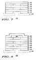
- FIG. 7 illustrates a cross-sectional view of a filter 700.
- filter 700 can be a more detailed view of filter 345 in FIGs. 4 and 6 .
- Support member 340 of FIGs. 4 and 6 is shown in FIG. 7 in dashed lines to illustrate how filter 700 can be used in component 100 of FIGs. 4 and 6 .
- Filter 700 comprises adhesives 710, 730, and 750 and also comprises layers 720, 740, and 760.
- layers 720, 740, and 760 can be comprised of a polyester material, a nylon material, and a PolyTetraFluoroEthylene (PTFE) material, respectively.
- Filter 700 is commercially available from the Donaldson Company, Inc. of Minneapolis, Minnesota and can also be purchased from Pall Specialty Materials of Port Washington, New York.
- the polyester material of layer 720 and/or the nylon material of layer 740 can provide some filtering characteristics for filter 700.
- the polyester and/or nylon materials can be treated with one or more chemicals to be hydrophobic and/or oleophobic.
- layer 740 can be comprised of, for example, a non-woven nylon material and can be adhered to layers 720 and/or 760 using an adhesive lamination.
- layer 720 can be adhered to support member 340 and/or layer 740 using a thermal pressure lamination.
- the PTFE material of layer 760 is porous to provide at least some of the filtering characteristics for filter 700.
- the porous nature of PTFE material can be provided by holes in the PTFE material that are smaller than 1 micrometer in diameter. As an example, the holes can be approximately 0.05 - 0.1 micrometers in diameter.
- PTFE material can include the following: (1) a silicone-free PTFE material, (2) a thickness of approximately 0.01 - 0.1 centimeters at approximately 3.4 kiloPascals, (3) a Mullen hydrostatic / water intrusion pressure (American Society for Testing and Materials (ASTM) D751) of approximately 850 - 950 kiloPascals, (4) an oil repellency index of approximately 7 according to the American Association of Textile Chemists / Colorists (AATCC) 118 - 1992 standard test method, (5) a Frazier permeability (ASTM D737) of approximately 3350 - 3450 liters per hour at approximately 12.7 millimeters of water, (6) a Fomblin efficiency of approximately 99.9 - 99.999 percent minimum on approximately 0.1 micrometers at 1.8 x 10 4 liters per hour, (7) an IsoPropyl Alcohol (IPA) bubble point of approximately 250 - 300 kiloPascals at approximately 10.0 milliliter
- the PTFE material can be a Teflon® material, which is commercially available from E. I. du Pont de Nemours and Company of Wilmington, Delaware, or a Gore-Tex® material, which is commercially available from W. L. Gore & Associates of Newark, Delaware. If a Tetlon® material is used for layer 760, layer 760 can also be hydrophobic and can control the humidity level within cavity 125 of component 100 in FIG. 6 .
- FIG. 8 illustrates a cross-sectional view of a filter 800.
- filter 800 can be a more detailed view of filter 345 in FIGS. 4 and 6 .
- Support member 340 of FIGs. 4 and 6 is shown in FIG. 8 in dashed lines to illustrate how filter 800 can be used in component 100 of FIGs. 4 and 6 .
- Filter 800 comprises adhesives 810, 830, 850, and 870 and also comprises layers 820, 840, 860, 880, and 890.
- layers 820, 840, and 860 can be comprised of a polyester material, a PolyTetraFluoroEthylene (PTFE) material, and a nylon material, respectively.
- Layers 820, 840, and 860 in FIG. 8 can be similar to layers 720, 760, and 740, respectively, in FIG. 7 .
- Layers 880 and 890 in FIG. 8 can be, for example, an activated carbon material and an outer scrim, respectively.
- Filter 800 is commercial available from the Donaldson Company, Inc. of Minneapolis, Minnesota and can also be purchased from Pall Specialty Materials of Port Washington, New York.
- FIG. 9 illustrates a cross-sectional view of a component 900, which can be a different embodiment of component 100 in FIG. 6 .
- Component 900 in FIG. 9 comprises an additional or second support member 950. Similar to support member 550 in FIG. 6 , support member 950 in FIG. 9 can further improve the mechanical support, stability, and reliability of filter 345.
- Support member 950 is located over at least a portion of housing 110, over cavity 125, and over filter 345. Support member 950 is preferably supported over cavity 125 by filter 345. Support member 950 is also located within recess 115 of housing 110. In FIG. 9 , housing 110 is illustrated without the protrusions that are illustrated to extend from surface 121 of rim 120 in FIG. 6 .
- Support member 950 has a hole 951 over filter 345, over hole 341 in support member 340, and over cavity 125 to permit communication between sensor element 105 and the environment outside component 900.
- Support member 950 and hole 951 in FIG. 9 can be similar to support member 550 and hole 551 in FIG. 6 .
- Support member 950 is preferably chemically coupled or otherwise adhered to housing 110 by an adhesive 960.
- adhesive 960 can be similar to adhesive 135.
- adhesives 135 and 960 can be considered one adhesive that has a height from rim 120 that is at least as high as the top surface of support member 950.
- support member 950 can also be mechanically coupled to housing 110 by swaging portion 555 of the walls defining recess 115.
- Support member 950 can be approximately the same size as support member 340 to permit adhesive 135 to be located between an edge of support member 950 and the vertical sidewall of housing 110. In this embodiment, adhesive 135 can further improve the reliability of the continuous seal at the perimeter of recess 115.
- FIG. 10 illustrates a cross-sectional view of a component 1000, which can be a different embodiment of component 100 in FIG. 6 .
- Component 1000 in FIG. 10 comprises a filter 1045.
- Filter 1045 in FIG. 10 can be similar in function and material composition as filter 345 in FIG. 6 .
- Filter 1045 is located over support member 340.
- Filter 1045 is also located over hole 341 in support member 340 and is further located over at least a portion of housing 110.
- housing 110 is illustrated without the protrusions that are illustrated to extend from surface 121 of rim 120 in FIG. 6 .
- Filter 1045 is preferably located outside of housing 110 and is supported over cavity 125 by rim or portion 555 of housing 110.
- support member 340 can support filter 1045 over cavity 125 of housing 110.
- housing 110 can still have rim 120, but housing can be shorter in height.
- filter 1045 can also be chemically coupled or otherwise adhered to support member 340.
- component 1000 also comprises an additional or second support member 1050. Similar to support member 550 in FIG. 6 , support member 1050 in FIG. 10 can further improve the mechanical support, stability, and reliability of filter 1045 in component 1000. Support member 1050 in FIG. 10 , however, is a skirt or flange.
- Support member 1050 is located over at least a portion of housing 110, over cavity 125, and over filter 1045. Support member 1050 is preferably supported over cavity 125 by filter 1045. Support member 1050 is also preferably located outside of housing 110. Support member 1050 has a hole 1051 over filter 1045, over hole 341 in support member 340, and over cavity 125 to permit communication between sensor element 105 and the environment outside component 1000. Support member 1050 in FIG. 10 can be similar in material composition to support member 550 in FIG. 6 , and hole 1051 in FIG. 10 can be similar to the size of hole 551 in FIG. 6 . Support member 1050, however, is preferably chemically coupled or otherwise adhered to housing 110 by an adhesive 1060 located outside of housing 110. In one embodiment, adhesive 1060 can be similar to adhesive 135.
- FIG. 11 illustrates a cross-sectional view of a component 1100, which can be a different embodiment of component 1000 in FIG. 10 .
- Component 1100 in FIG. 11 comprises a housing 1110.
- Housing 1110 in FIG. 11 can be similar to housing 110 in FIG. 6 .
- housing 1110 in FIG. 11 has a cavity 1125 similar to cavity 125 of housing 110 in FIG. 6 , but housing 1110 in FIG. 11 does not have an upper rim inside a recess of housing 1110.
- Component 1100 also comprises a support member 1140.
- Support member 1140 is located over at least a portion of housing 110 and over.cavity 125.
- Support member 1140 is preferably located outside of housing 110. and is supported over cavity 125 by a rim or portion 1155 of housing 110.
- Support member 1140 has a hole 1 141 over cavity 125 to permit communication between sensor element 105 and the environment outside component 1100.
- Support member 1140 in FIG. 11 can be similar to support member 340 in FIG. 6
- hole 1141 in FIG. 1 can be similar to hole 341 in FIG. 6 .
- Support member 1140 can be chemically coupled or otherwise adhered to housing 110, and/or support member 1140 can be coupled to housing 110 by filter 1045, support member 1050, and adhesive 1060.
- FIG. 12 illustrates a flow chart 1200 of a method of manufacturing a component.
- the component of flow chart 1200 can be similar to components 100, 900, 1000, or 1100 in FIGs. 6 , 9 , 10 , and 11 , respectively.
- a housing at least partially defining a cavity is provided.
- a sensor element is placed, positioned, or otherwise disposed in the cavity.
- an adhesive is placed, positioned, or otherwise disposed over a portion of the housing.
- the adhesive can be dispensed in a continuos bead over a rim of the housing.
- the rim can be roughened or can receive surface activation (i.e., ultra-violet light) before disposing the adhesive over the housing.
- a support member and a filter are placed, positioned, or otherwise disposed over the adhesive, over the cavity, and over at least a portion of the housing.
- the support member has a hole located over the cavity, and the filter is located over the support member and over the hole in the support member.
- Step 1240 can displace at least a portion of the adhesive. This displacement can increase the height of the adhesive.
- the displacement of the adhesive can be accomplished by using the support member to apply pressure to the adhesive when disposing the support member over the adhesive.
- the filter can be provided to be attached or otherwise coupled to the support member, and then the support member and the filter can be simultaneously disposed over the adhesive, the cavity, and at least a potion of the housing.
- the support member can be first disposed over the adhesive, and then, the filter can be disposed over the support member.
- the adhesive is cured.
- the curing process of step 1250 can be performed for approximately one hour at approximately 150 degrees Celsius.
- the adhesive is cured to preferably form a continuous seal between the support member and the housing.
- step 1260 of flow chart 1200 an additional support member is placed, positioned, or otherwise disposed over the filter and the support member.
- step 1260 occurs after step 1250 to prevent excessive displacement of the adhesive.
- a rim or other portion of the housing is swaged or otherwise deformed.
- step 1270 is performed after step 1260 to prevent excessive displacement of the adhesive.
- the swaging process of step 1270 mechanically couples the additional support member to the housing and preferably uses both elevated pressure and elevated temperature.
- FIG. 13 illustrates a flow chart 1300 of a method of operating a component.
- the component can be similar to components 100, 900, 1000, or 1100 in FIGs. 6 , 9 , 10 , and 11 , respectively.
- a component is provided to comprise a housing at least partially defining a cavity, a sensor element in the cavity, a support member over the cavity and over at least a portion of the housing and having a hole over the cavity, a filter over the support member and over the hole in the support member, and an additional, but optional, support member over the filter and having an additional hole over the filter and the hole in the support member.
- the sensor element is used to detect a first characteristic of the environment.
- the first characteristic of the environment can be a pressure of the environment.
- the filter is used to protect the sensor element from a second characteristic of the environment.
- the filter can be used to prevent the second characteristic from entering the cavity in the housing.
- the second characteristic of the environment can be, for example, a corrosive element or media.
- the support member is used to protect the filter from deforming beyond a predetermined amount
- the additional support member is used to protect the filter from deforming beyond an additional predetermined amount.
- the predetermined amount of step 1350 can be in a first direction
- the additional predetermined amount of step 1360 can be in a second direction different from the first direction.
- the first and second directions are opposite each other.
- an improved component is provided to overcome the disadvantages of the prior art.
- the components described herein provide effective corrosion protection while not adversely affecting the performance of the component.
- the location of the filter between two support members improves the robustness of the filter to prevent, or at least reduce, mechanical failures of the filter due to large and/or quick changes in pressure.
- the easy assembly methods for the component also minimize the manufacturing costs of the component.
- a coating or encapsulant can be used inside the cavity in the housing, and the components can be devoid of electrical leads.
- the support members and/or filters can be permanently attached to each other and/or the housing.
- the support members and/or filters can be removable, interchangeable, and/or replaceable parts, but such replacement constitutes reconstructing or rebuilding the component and not repair of the component.
- steps 1320, 1330, 1340, 1350, and 1360 in flow chart 1300 of FIG. 13 or any subset thereof can be performed simultaneously with each other.
- the two support members and the filter can be pre-assembled together, and this assembly can be disposed over the adhesive, over the cavity, and over at least a portion of the housing during step 1240 of flow chart 1200 in FIG. 12 .
- step 1260 is eliminated, and step 1270 is optional.
Landscapes
- Physics & Mathematics (AREA)
- General Physics & Mathematics (AREA)
- Measuring Fluid Pressure (AREA)
Claims (13)
- Komponente, die umfasst:ein Gehäuse (110), das mindestens teilweise einen Hohlraum definiert, wobei das Gehäuse einen Rand (120) umfasst, der über eine Oberfläche (121) verfügt;ein Sensorelement (105) in dem Hohlraum;einen Filter (345);ein Unterstützungselement (340), das einen Teil umfasst, der über der Oberfläche des Randes (120) angeordnet ist, wobei mindestens ein Teil des Unterstützungselementes (340) unter dem Filter (345) angeordnet ist, um eine Unterstützung für den Filter (345) über dem Hohlraum zur Verfügung zu stellen, wobei der mindestens eine Teil des Unterstützungselementes (340), der unter dem Filter (345) angeordnet ist, ein Loch über dem Hohlraum definiert;eine Mehrzahl von Vorsprüngen (122), die sich von der Oberfläche (121) erstrecken und die Oberfläche (121) des Randes (120) und den Teil des Unterstützungselementes (340), der über der Oberfläche des Randes (120) angeordnet ist, trennen, wobei die Mehrzahl von Vorsprüngen (122) das Unterstützungselement (340) über der Oberfläche (121) des Randes (121) unterstützt;einen Klebstoff (135), der mindestens zwischen der Oberfläche (121) des Randes (120) und dem Teil des Unterstützungselementes, der über der Oberfläche des Randes angeordnet ist, angeordnet ist.
- Komponente gemäß Anspruch 1, wobei:der Klebstoff (135) das Unterstützungselement (340) an den Rand (120) klebt;wobei der Klebstoff (135) eine kontinuierliche Dichtung zwischen dem Unterstützungselement (340) und dem Gehäuse (110) bildet.
- Komponente gemäß Anspruch 2, wobei:das Unterstützungselement (340) über eine erste Seite (342), die dem Hohlraum zugewandt ist, eine zweite Seite (343), die dem Filter (345) zugewandt ist, und eine Zarge (344), die die erste und zweite Seite (342, 343) zusammen koppelt, verfügt; undder Klebstoff (135) die erste Seite (342) und die Zarge (344) des Unterstützungselementes an das Gehäuse (110) klebt.
- Komponente gemäß Anspruch 3, wobei:die Zarge (344) über eine Höhe verfügt; undder Klebstoff (135) über eine Höhe von dem Rand verfügt, die mindestens genau so hoch wie die Höhe der Zarge (344) ist.
- Komponente gemäß Anspruch 1, wobei:das Unterstützungselement (340) über eine erste Seite (342), die dem Hohlraum zugewandt ist, eine zweite Seite (343), die dem Filter (345) zugewandt ist, und eine Zarge (344), die die erste und zweite Seite zusammen koppelt, verfügt;die Mehrzahl von Vorsprüngen (122) die erste Seite des Unterstützungselementes (340) über der Oberfläche (121) des Randes (120) unterstützt;der Klebstoff (135) mindestens zwischen der Oberfläche (121) des Randes (120) und der ersten Seite (342) des Unterstützungselementes (340) angeordnet ist; undder Klebstoff (135) die Zarge (344) des Unterstützungselementes (340) an das Gehäuse (110) und einen Umfang der ersten Seite (342) des Unterstützungselementes (340) an den Rand (120) klebt.
- Komponente gemäß Anspruch 1 oder 2, wobei:der Rand (120) kontinuierlich ist; undder Klebstoff (135) über dem Rand (120) kontinuierlich ist.
- Komponente gemäß einem der vorangehenden Ansprüche, wobei:das Unterstützungselement (340) und der Filter (345) in dem Gehäuse (110) angeordnet sind.
- Komponente gemäß einem der vorangehenden Ansprüche, die weiterhin umfasst:ein zusätzliches Unterstützungselement (550) über dem Filter (345), das über ein zusätzliches Loch über dem Filter (345) und dem Loch in dem Unterstützungselement (340) verfügt.
- Komponente gemäß Anspruch 8, wobei:ein Teil des Gehäuses (110) über dem zusätzlichen Unterstützungselement (550) liegt.
- Komponente gemäß Anspruch 8, wobei:das Unterstützungselement (340), der Filter (345) und das zusätzliche Unterstützungselement (550) in dem Gehäuse (110) angeordnet sind.
- Komponente gemäß einem der vorangehenden Ansprüche, wobei:die Vorsprünge (122) eine Dicke des Klebstoffs (135) zwischen der Oberfläche (121) des Randes (120) und dem Teil des Unterstützungselementes (340) über der Oberfläche (121) des Randes (120) gewährleisten.
- Komponente gemäß einem der vorangehenden Ansprüche, die weiterhin umfasst:elektrische Leitungen (101) in dem Hohlraum, die sich durch das Gehäuse (110) erstrecken und aus dem Gehäuse (110) herausragen.
- Komponente gemäß einem der vorangehenden Ansprüche, die weiterhin umfasst:ein elektronisches Element (106) in dem Hohlraum, das an das Sensorelement (105) angrenzt und mit diesem elektrisch gekoppelt ist.
Applications Claiming Priority (3)
| Application Number | Priority Date | Filing Date | Title |
|---|---|---|---|
| US901366 | 1986-08-28 | ||
| US09/901,366 US6769319B2 (en) | 2001-07-09 | 2001-07-09 | Component having a filter |
| PCT/US2002/018501 WO2003006929A1 (en) | 2001-07-09 | 2002-06-10 | Component with filter and method of manufacturing |
Publications (2)
| Publication Number | Publication Date |
|---|---|
| EP1407232A1 EP1407232A1 (de) | 2004-04-14 |
| EP1407232B1 true EP1407232B1 (de) | 2013-12-25 |
Family
ID=25414031
Family Applications (1)
| Application Number | Title | Priority Date | Filing Date |
|---|---|---|---|
| EP02729351.3A Expired - Lifetime EP1407232B1 (de) | 2001-07-09 | 2002-06-10 | Komponent mit filter |
Country Status (4)
| Country | Link |
|---|---|
| US (1) | US6769319B2 (de) |
| EP (1) | EP1407232B1 (de) |
| JP (1) | JP2004522170A (de) |
| WO (1) | WO2003006929A1 (de) |
Families Citing this family (30)
| Publication number | Priority date | Publication date | Assignee | Title |
|---|---|---|---|---|
| US7017433B2 (en) * | 2001-10-04 | 2006-03-28 | Ssi Technologies, Inc. | Non-contacting sensor multichip module with integral heat-sinks |
| US6886929B2 (en) * | 2002-10-25 | 2005-05-03 | Hewlett-Packard Development Company, L.P. | Techniques for improving pressure sensor shock robustness in fluid containment devices |
| US7465040B2 (en) * | 2002-10-25 | 2008-12-16 | Hewlett-Packard Development Company, L.P. | Labyrinth seal structure with redundant fluid flow paths |
| GB0315489D0 (en) * | 2003-07-02 | 2003-08-06 | Melexis Nv | Pressure sensor |
| TWI228811B (en) * | 2004-05-28 | 2005-03-01 | Taiwan Electronic Packaging Co | Package for integrated circuit chip |
| JP2007024545A (ja) * | 2005-07-12 | 2007-02-01 | Denso Corp | 光検知式ガスセンサ装置 |
| JP4534912B2 (ja) * | 2005-08-30 | 2010-09-01 | 株式会社デンソー | 角速度センサの取付構造 |
| US7329932B2 (en) * | 2005-09-12 | 2008-02-12 | Teledyne Licensing, Llc | Microelectromechanical (MEM) viscosity sensor and method |
| JP4568202B2 (ja) * | 2005-09-29 | 2010-10-27 | Okiセミコンダクタ株式会社 | 半導体装置 |
| JP2007114001A (ja) * | 2005-10-19 | 2007-05-10 | Denso Corp | 圧力センサ |
| US7377177B1 (en) | 2007-04-13 | 2008-05-27 | Honeywell International Inc. | Pressure sensor method and apparatus |
| JP4197024B2 (ja) * | 2006-09-06 | 2008-12-17 | トヨタ自動車株式会社 | 車輪状態検出装置および車輪状態監視装置 |
| DE102006048068A1 (de) * | 2006-10-11 | 2008-04-17 | Atmel Germany Gmbh | Fluidsensor |
| US7478554B2 (en) * | 2006-12-19 | 2009-01-20 | The Goodyear Tire & Rubber Company | Rim mounted tire pressure monitoring system |
| US20080222884A1 (en) * | 2007-03-14 | 2008-09-18 | Honeywell International Inc. | Packaging for chip-on-board pressure sensor |
| JP4365426B2 (ja) * | 2007-04-13 | 2009-11-18 | カルソニックカンセイ株式会社 | メータ装置 |
| EP2213406B1 (de) * | 2009-02-02 | 2011-03-30 | Pepperl + Fuchs GmbH | Sensorgehäuse |
| US8359927B2 (en) * | 2009-08-12 | 2013-01-29 | Freescale Semiconductor, Inc. | Molded differential PRT pressure sensor |
| JP4968371B2 (ja) * | 2010-06-30 | 2012-07-04 | 大日本印刷株式会社 | センサデバイスの製造方法及びセンサデバイス |
| CN103038021B (zh) * | 2010-07-02 | 2015-05-06 | 倍加福有限公司 | 传感器壳体 |
| US8476087B2 (en) | 2011-04-21 | 2013-07-02 | Freescale Semiconductor, Inc. | Methods for fabricating sensor device package using a sealing structure |
| US8384168B2 (en) * | 2011-04-21 | 2013-02-26 | Freescale Semiconductor, Inc. | Sensor device with sealing structure |
| US9046546B2 (en) | 2012-04-27 | 2015-06-02 | Freescale Semiconductor Inc. | Sensor device and related fabrication methods |
| US9046426B1 (en) * | 2012-06-15 | 2015-06-02 | The United States Of America As Represented By The Administrator Of National Aeronautics And Space Administration | Modular apparatus and method for attaching multiple devices |
| JP6257503B2 (ja) * | 2014-12-08 | 2018-01-10 | アルプス電気株式会社 | 圧力検知装置 |
| JP6565867B2 (ja) * | 2016-10-28 | 2019-08-28 | 株式会社デンソー | 空気物理量センサ |
| US11745549B2 (en) * | 2017-08-21 | 2023-09-05 | Sram. Llc | Pressure sensing assembly for a bicycle wheel |
| US11837513B2 (en) * | 2019-07-17 | 2023-12-05 | Texas Instruments Incorporated | O-ring seals for fluid sensing |
| US12344051B2 (en) | 2019-10-31 | 2025-07-01 | Cerebrum Sensor Technologies, Inc. | Sensor assemblies and systems for monitoring a dynamic object |
| US12429414B2 (en) * | 2020-01-31 | 2025-09-30 | Kidde Fire Protection, Llc | Method for manufacturing a detector |
Family Cites Families (53)
| Publication number | Priority date | Publication date | Assignee | Title |
|---|---|---|---|---|
| US2951371A (en) * | 1956-08-06 | 1960-09-06 | Gen Dynamics Corp | Holder for force sensing device |
| US3334204A (en) * | 1965-09-09 | 1967-08-01 | Honeywell Inc | Pressure retard switch |
| US3574284A (en) | 1967-06-26 | 1971-04-13 | Laucks Lab Inc | Pore pressure apparatus and method |
| US3619742A (en) | 1970-05-21 | 1971-11-09 | Rosemount Eng Co Ltd | Shielded capacitance pressure sensor |
| US3718566A (en) * | 1971-01-07 | 1973-02-27 | Instrumentation Labor Inc | Polarographic electrode assembly |
| FR2224752B1 (de) * | 1973-04-09 | 1977-09-02 | Thomson Medical Telco | |
| US4034609A (en) | 1976-01-02 | 1977-07-12 | Fuller David L | Digital sensing device |
| US4177496A (en) | 1976-03-12 | 1979-12-04 | Kavlico Corporation | Capacitive pressure transducer |
| DE2935476B2 (de) * | 1979-09-01 | 1981-07-09 | Hottinger Baldwin Messtechnik Gmbh, 6100 Darmstadt | Flüssigkeitsgefüllter Differenzdruckaufnehmer |
| US4571244A (en) | 1984-05-07 | 1986-02-18 | Biogenesis, Inc. | System for removing gas bubbles from liquids |
| US4734674A (en) | 1985-04-08 | 1988-03-29 | Jack Taylor | Tire pressure warning system |
| US4732042A (en) | 1986-04-22 | 1988-03-22 | Motorola Inc. | Cast membrane protected pressure sensor |
| US4686764A (en) | 1986-04-22 | 1987-08-18 | Motorola, Inc. | Membrane protected pressure sensor |
| JPH0810170B2 (ja) | 1987-03-06 | 1996-01-31 | 株式会社日立製作所 | 半導体絶対圧力センサの製造方法 |
| US4909070A (en) | 1987-10-12 | 1990-03-20 | Smith Jeffery B | Moisture sensor |
| JPH0812123B2 (ja) * | 1987-11-27 | 1996-02-07 | 日本碍子株式会社 | 圧力センサ |
| CA1324892C (en) | 1988-03-03 | 1993-12-07 | Edward F. Koen | Protected pressure sensor |
| US4993265A (en) | 1988-03-03 | 1991-02-19 | The Foxboro Company | Protected pressure sensor and method of making |
| US4942383A (en) | 1989-03-06 | 1990-07-17 | Honeywell Inc. | Low cost wet-to-wet pressure sensor package |
| JPH04258176A (ja) | 1991-02-12 | 1992-09-14 | Mitsubishi Electric Corp | 半導体圧力センサ |
| DE4133061A1 (de) | 1991-10-04 | 1993-04-15 | Bosch Gmbh Robert | Drucksensor |
| US5333505A (en) | 1992-01-13 | 1994-08-02 | Mitsubishi Denki Kabushiki Kaisha | Semiconductor pressure sensor for use at high temperature and pressure and method of manufacturing same |
| FR2686692B1 (fr) | 1992-01-28 | 1996-08-23 | Jaeger | Capteur de pression a base de semi-conducteur et procede de fabrication. |
| US5308939A (en) | 1992-07-21 | 1994-05-03 | Fuji Koki Manufacturing Co., Ltd. | Pressure equalizing mechanism for a pressure switch |
| US5612576A (en) | 1992-10-13 | 1997-03-18 | Motorola | Self-opening vent hole in an overmolded semiconductor device |
| JPH06132545A (ja) | 1992-10-19 | 1994-05-13 | Mitsubishi Electric Corp | 圧力検出装置 |
| JPH07120340A (ja) | 1993-10-22 | 1995-05-12 | Honda Motor Co Ltd | 圧力センサ |
| US5583370A (en) | 1994-03-04 | 1996-12-10 | Motorola Inc. | Tab semiconductor device having die edge protection and method for making the same |
| DE4413274A1 (de) | 1994-04-16 | 1995-10-19 | Sel Alcatel Ag | Drucksensor |
| WO1996003629A1 (de) | 1994-07-21 | 1996-02-08 | Siemens Aktiengesellschaft | Schutzmembran für einen siliziumdrucksensor |
| SE9402720D0 (sv) | 1994-08-15 | 1994-08-15 | Gambro Ab | Insats för tryckgivare |
| JPH08178778A (ja) | 1994-12-27 | 1996-07-12 | Mitsubishi Electric Corp | 半導体圧力検出装置 |
| US5889211A (en) | 1995-04-03 | 1999-03-30 | Motorola, Inc. | Media compatible microsensor structure and methods of manufacturing and using the same |
| US5747694A (en) | 1995-07-28 | 1998-05-05 | Nippondenso Co., Ltd. | Pressure sensor with barrier in a pressure chamber |
| US5600071A (en) | 1995-09-05 | 1997-02-04 | Motorola, Inc. | Vertically integrated sensor structure and method |
| JP3144279B2 (ja) | 1995-09-18 | 2001-03-12 | 株式会社村田製作所 | センサ製造用パレット及び赤外線センサの製造方法 |
| US5700981A (en) | 1996-02-08 | 1997-12-23 | Micron Communications, Inc. | Encapsulated electronic component and method for encapsulating an electronic component |
| US6067709A (en) | 1996-02-23 | 2000-05-30 | Mpm Corporation | Applying encapsulating material to substrates |
| US6117086A (en) * | 1996-04-18 | 2000-09-12 | Sunscope International, Inc. | Pressure transducer apparatus with disposable dome |
| US5993395A (en) * | 1996-04-18 | 1999-11-30 | Sunscope International Inc. | Pressure transducer apparatus with disposable dome |
| US5894167A (en) | 1996-05-08 | 1999-04-13 | Micron Technology, Inc. | Encapsulant dam standoff for shell-enclosed die assemblies |
| DE19626086A1 (de) | 1996-06-28 | 1998-01-02 | Siemens Ag | Auf der Bestückungsoberfläche einer Leiterplatte montierbares Drucksensor-Bauelement |
| DE19626083C2 (de) | 1996-06-28 | 2000-03-23 | Siemens Ag | Sensor-Bauelement |
| US5981314A (en) | 1996-10-31 | 1999-11-09 | Amkor Technology, Inc. | Near chip size integrated circuit package |
| US5929512A (en) | 1997-03-18 | 1999-07-27 | Jacobs; Richard L. | Urethane encapsulated integrated circuits and compositions therefor |
| US5977622A (en) | 1997-04-25 | 1999-11-02 | Lsi Logic Corporation | Stiffener with slots for clip-on heat sink attachment |
| US5785791A (en) | 1997-05-05 | 1998-07-28 | Motorola, Inc. | Method of manufacturing semiconductor component |
| EP0918215B1 (de) * | 1997-11-21 | 2004-04-07 | Denso Corporation | Gassensor |
| US6191359B1 (en) | 1998-10-13 | 2001-02-20 | Intel Corporation | Mass reflowable windowed package |
| FR2787194B1 (fr) | 1998-12-11 | 2001-01-05 | Sagem | Detecteur d'acceleration de pneumatique de vehicule automobile |
| FR2787187B1 (fr) | 1998-12-11 | 2001-01-05 | Sagem | Module de mesure de pression de pneumatique |
| US6453749B1 (en) * | 1999-10-28 | 2002-09-24 | Motorola, Inc. | Physical sensor component |
| US6401545B1 (en) * | 2000-01-25 | 2002-06-11 | Motorola, Inc. | Micro electro-mechanical system sensor with selective encapsulation and method therefor |
-
2001
- 2001-07-09 US US09/901,366 patent/US6769319B2/en not_active Expired - Lifetime
-
2002
- 2002-06-10 EP EP02729351.3A patent/EP1407232B1/de not_active Expired - Lifetime
- 2002-06-10 WO PCT/US2002/018501 patent/WO2003006929A1/en not_active Ceased
- 2002-06-10 JP JP2003512649A patent/JP2004522170A/ja active Pending
Also Published As
| Publication number | Publication date |
|---|---|
| US20030005782A1 (en) | 2003-01-09 |
| JP2004522170A (ja) | 2004-07-22 |
| EP1407232A1 (de) | 2004-04-14 |
| US6769319B2 (en) | 2004-08-03 |
| WO2003006929A1 (en) | 2003-01-23 |
Similar Documents
| Publication | Publication Date | Title |
|---|---|---|
| US6769319B2 (en) | Component having a filter | |
| US5747694A (en) | Pressure sensor with barrier in a pressure chamber | |
| EP0386959B1 (de) | Konsumdirektdrucksensoreinheit | |
| US7436037B2 (en) | Moisture resistant pressure sensors | |
| US6148673A (en) | Differential pressure sensor and method thereof | |
| US7513149B1 (en) | Robust MEMS flow die with integrated protective flow channel | |
| US5629538A (en) | Semiconductor sensor having a protective layer | |
| US8024978B2 (en) | Media isolated pressure transducer having boss comprising single metal diaphragm | |
| US7024937B2 (en) | Isolated pressure transducer | |
| EP1096243B1 (de) | Halbleiterdruckwandler mit Filter | |
| US6320128B1 (en) | Environmentally-sealed electronic assembly and method of making same | |
| US8794074B2 (en) | Sensor module and method for producing a sensor module | |
| KR20110128293A (ko) | 노출 패드 후면 압력 센서 패키지 | |
| US10983022B2 (en) | Pressure sensor | |
| JP2000356561A (ja) | 半導体歪みセンサ | |
| CN104865002A (zh) | 一种mems压力传感器装置及封装方法 | |
| US5932809A (en) | Sensor with silicon strain gage | |
| CN1217059A (zh) | 在印刷线路板装配表面上可装配的压力传感器元件 | |
| US20080078251A1 (en) | Pressure sensor package structure | |
| US6971268B2 (en) | Pressure sensor having metallic diaphragm with convexity | |
| CN119935402A (zh) | 电子模块组件及压力传感器 | |
| US12196638B2 (en) | Pressure sensor with improved diaphragm seal | |
| EP0100221A2 (de) | Fluiddruck fühlende Vorrichtung und Verfahren zur Herstellung derselben | |
| US7451635B2 (en) | Sensor assembly with insert molded bead | |
| US6092425A (en) | Differential pressure sensor having an alloy or metal isolator |
Legal Events
| Date | Code | Title | Description |
|---|---|---|---|
| PUAI | Public reference made under article 153(3) epc to a published international application that has entered the european phase |
Free format text: ORIGINAL CODE: 0009012 |
|
| 17P | Request for examination filed |
Effective date: 20040209 |
|
| AK | Designated contracting states |
Kind code of ref document: A1 Designated state(s): AT BE CH CY DE DK ES FI FR GB GR IE IT LI LU MC NL PT SE TR |
|
| AX | Request for extension of the european patent |
Extension state: AL LT LV MK RO SI |
|
| RAP1 | Party data changed (applicant data changed or rights of an application transferred) |
Owner name: FREESCALE SEMICONDUCTOR, INC. |
|
| 17Q | First examination report despatched |
Effective date: 20091112 |
|
| GRAP | Despatch of communication of intention to grant a patent |
Free format text: ORIGINAL CODE: EPIDOSNIGR1 |
|
| INTG | Intention to grant announced |
Effective date: 20130618 |
|
| GRAP | Despatch of communication of intention to grant a patent |
Free format text: ORIGINAL CODE: EPIDOSNIGR1 |
|
| GRAS | Grant fee paid |
Free format text: ORIGINAL CODE: EPIDOSNIGR3 |
|
| INTG | Intention to grant announced |
Effective date: 20131024 |
|
| GRAA | (expected) grant |
Free format text: ORIGINAL CODE: 0009210 |
|
| AK | Designated contracting states |
Kind code of ref document: B1 Designated state(s): AT BE CH CY DE DK ES FI FR GB GR IE IT LI LU MC NL PT SE TR |
|
| REG | Reference to a national code |
Ref country code: GB Ref legal event code: FG4D |
|
| REG | Reference to a national code |
Ref country code: CH Ref legal event code: EP |
|
| REG | Reference to a national code |
Ref country code: DE Ref legal event code: R081 Ref document number: 60245885 Country of ref document: DE Owner name: NXP USA, INC. (N.D.GES.D.STAATES DELAWARE), AU, US Free format text: FORMER OWNER: MOTOROLA, INC., SCHAUMBURG, ILL., US |
|
| REG | Reference to a national code |
Ref country code: AT Ref legal event code: REF Ref document number: 646853 Country of ref document: AT Kind code of ref document: T Effective date: 20140115 |
|
| REG | Reference to a national code |
Ref country code: IE Ref legal event code: FG4D |
|
| REG | Reference to a national code |
Ref country code: DE Ref legal event code: R096 Ref document number: 60245885 Country of ref document: DE Effective date: 20140213 |
|
| PG25 | Lapsed in a contracting state [announced via postgrant information from national office to epo] |
Ref country code: SE Free format text: LAPSE BECAUSE OF FAILURE TO SUBMIT A TRANSLATION OF THE DESCRIPTION OR TO PAY THE FEE WITHIN THE PRESCRIBED TIME-LIMIT Effective date: 20131225 Ref country code: FI Free format text: LAPSE BECAUSE OF FAILURE TO SUBMIT A TRANSLATION OF THE DESCRIPTION OR TO PAY THE FEE WITHIN THE PRESCRIBED TIME-LIMIT Effective date: 20131225 |
|
| REG | Reference to a national code |
Ref country code: NL Ref legal event code: VDEP Effective date: 20131225 |
|
| REG | Reference to a national code |
Ref country code: AT Ref legal event code: MK05 Ref document number: 646853 Country of ref document: AT Kind code of ref document: T Effective date: 20131225 |
|
| PG25 | Lapsed in a contracting state [announced via postgrant information from national office to epo] |
Ref country code: BE Free format text: LAPSE BECAUSE OF FAILURE TO SUBMIT A TRANSLATION OF THE DESCRIPTION OR TO PAY THE FEE WITHIN THE PRESCRIBED TIME-LIMIT Effective date: 20131225 |
|
| PG25 | Lapsed in a contracting state [announced via postgrant information from national office to epo] |
Ref country code: NL Free format text: LAPSE BECAUSE OF FAILURE TO SUBMIT A TRANSLATION OF THE DESCRIPTION OR TO PAY THE FEE WITHIN THE PRESCRIBED TIME-LIMIT Effective date: 20131225 Ref country code: PT Free format text: LAPSE BECAUSE OF FAILURE TO SUBMIT A TRANSLATION OF THE DESCRIPTION OR TO PAY THE FEE WITHIN THE PRESCRIBED TIME-LIMIT Effective date: 20140428 Ref country code: ES Free format text: LAPSE BECAUSE OF FAILURE TO SUBMIT A TRANSLATION OF THE DESCRIPTION OR TO PAY THE FEE WITHIN THE PRESCRIBED TIME-LIMIT Effective date: 20131225 Ref country code: CY Free format text: LAPSE BECAUSE OF FAILURE TO SUBMIT A TRANSLATION OF THE DESCRIPTION OR TO PAY THE FEE WITHIN THE PRESCRIBED TIME-LIMIT Effective date: 20131225 Ref country code: AT Free format text: LAPSE BECAUSE OF FAILURE TO SUBMIT A TRANSLATION OF THE DESCRIPTION OR TO PAY THE FEE WITHIN THE PRESCRIBED TIME-LIMIT Effective date: 20131225 |
|
| REG | Reference to a national code |
Ref country code: DE Ref legal event code: R097 Ref document number: 60245885 Country of ref document: DE |
|
| PG25 | Lapsed in a contracting state [announced via postgrant information from national office to epo] |
Ref country code: DK Free format text: LAPSE BECAUSE OF FAILURE TO SUBMIT A TRANSLATION OF THE DESCRIPTION OR TO PAY THE FEE WITHIN THE PRESCRIBED TIME-LIMIT Effective date: 20131225 |
|
| PLBE | No opposition filed within time limit |
Free format text: ORIGINAL CODE: 0009261 |
|
| STAA | Information on the status of an ep patent application or granted ep patent |
Free format text: STATUS: NO OPPOSITION FILED WITHIN TIME LIMIT |
|
| 26N | No opposition filed |
Effective date: 20140926 |
|
| REG | Reference to a national code |
Ref country code: DE Ref legal event code: R097 Ref document number: 60245885 Country of ref document: DE Effective date: 20140926 |
|
| PG25 | Lapsed in a contracting state [announced via postgrant information from national office to epo] |
Ref country code: LU Free format text: LAPSE BECAUSE OF FAILURE TO SUBMIT A TRANSLATION OF THE DESCRIPTION OR TO PAY THE FEE WITHIN THE PRESCRIBED TIME-LIMIT Effective date: 20140610 Ref country code: MC Free format text: LAPSE BECAUSE OF FAILURE TO SUBMIT A TRANSLATION OF THE DESCRIPTION OR TO PAY THE FEE WITHIN THE PRESCRIBED TIME-LIMIT Effective date: 20131225 |
|
| REG | Reference to a national code |
Ref country code: CH Ref legal event code: PL |
|
| REG | Reference to a national code |
Ref country code: IE Ref legal event code: MM4A |
|
| PG25 | Lapsed in a contracting state [announced via postgrant information from national office to epo] |
Ref country code: IE Free format text: LAPSE BECAUSE OF NON-PAYMENT OF DUE FEES Effective date: 20140610 Ref country code: CH Free format text: LAPSE BECAUSE OF NON-PAYMENT OF DUE FEES Effective date: 20140630 Ref country code: LI Free format text: LAPSE BECAUSE OF NON-PAYMENT OF DUE FEES Effective date: 20140630 |
|
| REG | Reference to a national code |
Ref country code: FR Ref legal event code: PLFP Year of fee payment: 15 |
|
| PG25 | Lapsed in a contracting state [announced via postgrant information from national office to epo] |
Ref country code: IT Free format text: LAPSE BECAUSE OF FAILURE TO SUBMIT A TRANSLATION OF THE DESCRIPTION OR TO PAY THE FEE WITHIN THE PRESCRIBED TIME-LIMIT Effective date: 20131225 Ref country code: GR Free format text: LAPSE BECAUSE OF FAILURE TO SUBMIT A TRANSLATION OF THE DESCRIPTION OR TO PAY THE FEE WITHIN THE PRESCRIBED TIME-LIMIT Effective date: 20140326 |
|
| PG25 | Lapsed in a contracting state [announced via postgrant information from national office to epo] |
Ref country code: TR Free format text: LAPSE BECAUSE OF FAILURE TO SUBMIT A TRANSLATION OF THE DESCRIPTION OR TO PAY THE FEE WITHIN THE PRESCRIBED TIME-LIMIT Effective date: 20131225 |
|
| REG | Reference to a national code |
Ref country code: FR Ref legal event code: PLFP Year of fee payment: 16 |
|
| REG | Reference to a national code |
Ref country code: FR Ref legal event code: TP Owner name: NXP USA, INC., US Effective date: 20170921 |
|
| REG | Reference to a national code |
Ref country code: GB Ref legal event code: 732E Free format text: REGISTERED BETWEEN 20171109 AND 20171115 |
|
| REG | Reference to a national code |
Ref country code: DE Ref legal event code: R081 Ref document number: 60245885 Country of ref document: DE Owner name: NXP USA, INC. (N.D.GES.D.STAATES DELAWARE), AU, US Free format text: FORMER OWNER: FREESCALE SEMICONDUCTORS, INC., AUSTIN, TEX., US |
|
| REG | Reference to a national code |
Ref country code: FR Ref legal event code: PLFP Year of fee payment: 17 |
|
| PGFP | Annual fee paid to national office [announced via postgrant information from national office to epo] |
Ref country code: DE Payment date: 20190521 Year of fee payment: 18 |
|
| PGFP | Annual fee paid to national office [announced via postgrant information from national office to epo] |
Ref country code: FR Payment date: 20190522 Year of fee payment: 18 |
|
| PGFP | Annual fee paid to national office [announced via postgrant information from national office to epo] |
Ref country code: GB Payment date: 20190522 Year of fee payment: 18 |
|
| REG | Reference to a national code |
Ref country code: DE Ref legal event code: R119 Ref document number: 60245885 Country of ref document: DE |
|
| GBPC | Gb: european patent ceased through non-payment of renewal fee |
Effective date: 20200610 |
|
| PG25 | Lapsed in a contracting state [announced via postgrant information from national office to epo] |
Ref country code: GB Free format text: LAPSE BECAUSE OF NON-PAYMENT OF DUE FEES Effective date: 20200610 Ref country code: FR Free format text: LAPSE BECAUSE OF NON-PAYMENT OF DUE FEES Effective date: 20200630 |
|
| PG25 | Lapsed in a contracting state [announced via postgrant information from national office to epo] |
Ref country code: DE Free format text: LAPSE BECAUSE OF NON-PAYMENT OF DUE FEES Effective date: 20210101 |