EP1407152B1 - Pivot joint - Google Patents
Pivot joint Download PDFInfo
- Publication number
- EP1407152B1 EP1407152B1 EP02749025A EP02749025A EP1407152B1 EP 1407152 B1 EP1407152 B1 EP 1407152B1 EP 02749025 A EP02749025 A EP 02749025A EP 02749025 A EP02749025 A EP 02749025A EP 1407152 B1 EP1407152 B1 EP 1407152B1
- Authority
- EP
- European Patent Office
- Prior art keywords
- ball
- contact
- pivot joint
- joint according
- held
- Prior art date
- Legal status (The legal status is an assumption and is not a legal conclusion. Google has not performed a legal analysis and makes no representation as to the accuracy of the status listed.)
- Expired - Lifetime
Links
Images


Classifications
-
- G—PHYSICS
- G01—MEASURING; TESTING
- G01B—MEASURING LENGTH, THICKNESS OR SIMILAR LINEAR DIMENSIONS; MEASURING ANGLES; MEASURING AREAS; MEASURING IRREGULARITIES OF SURFACES OR CONTOURS
- G01B3/00—Measuring instruments characterised by the use of mechanical techniques
- G01B3/002—Details
-
- F—MECHANICAL ENGINEERING; LIGHTING; HEATING; WEAPONS; BLASTING
- F16—ENGINEERING ELEMENTS AND UNITS; GENERAL MEASURES FOR PRODUCING AND MAINTAINING EFFECTIVE FUNCTIONING OF MACHINES OR INSTALLATIONS; THERMAL INSULATION IN GENERAL
- F16C—SHAFTS; FLEXIBLE SHAFTS; ELEMENTS OR CRANKSHAFT MECHANISMS; ROTARY BODIES OTHER THAN GEARING ELEMENTS; BEARINGS
- F16C11/00—Pivots; Pivotal connections
- F16C11/04—Pivotal connections
- F16C11/06—Ball-joints; Other joints having more than one degree of angular freedom, i.e. universal joints
- F16C11/0619—Ball-joints; Other joints having more than one degree of angular freedom, i.e. universal joints the female part comprising a blind socket receiving the male part
- F16C11/0623—Construction or details of the socket member
-
- F—MECHANICAL ENGINEERING; LIGHTING; HEATING; WEAPONS; BLASTING
- F16—ENGINEERING ELEMENTS AND UNITS; GENERAL MEASURES FOR PRODUCING AND MAINTAINING EFFECTIVE FUNCTIONING OF MACHINES OR INSTALLATIONS; THERMAL INSULATION IN GENERAL
- F16M—FRAMES, CASINGS OR BEDS OF ENGINES, MACHINES OR APPARATUS, NOT SPECIFIC TO ENGINES, MACHINES OR APPARATUS PROVIDED FOR ELSEWHERE; STANDS; SUPPORTS
- F16M11/00—Stands or trestles as supports for apparatus or articles placed thereon ; Stands for scientific apparatus such as gravitational force meters
- F16M11/02—Heads
- F16M11/04—Means for attachment of apparatus; Means allowing adjustment of the apparatus relatively to the stand
- F16M11/06—Means for attachment of apparatus; Means allowing adjustment of the apparatus relatively to the stand allowing pivoting
- F16M11/12—Means for attachment of apparatus; Means allowing adjustment of the apparatus relatively to the stand allowing pivoting in more than one direction
- F16M11/121—Means for attachment of apparatus; Means allowing adjustment of the apparatus relatively to the stand allowing pivoting in more than one direction constituted of several dependent joints
-
- F—MECHANICAL ENGINEERING; LIGHTING; HEATING; WEAPONS; BLASTING
- F16—ENGINEERING ELEMENTS AND UNITS; GENERAL MEASURES FOR PRODUCING AND MAINTAINING EFFECTIVE FUNCTIONING OF MACHINES OR INSTALLATIONS; THERMAL INSULATION IN GENERAL
- F16M—FRAMES, CASINGS OR BEDS OF ENGINES, MACHINES OR APPARATUS, NOT SPECIFIC TO ENGINES, MACHINES OR APPARATUS PROVIDED FOR ELSEWHERE; STANDS; SUPPORTS
- F16M11/00—Stands or trestles as supports for apparatus or articles placed thereon ; Stands for scientific apparatus such as gravitational force meters
- F16M11/02—Heads
- F16M11/04—Means for attachment of apparatus; Means allowing adjustment of the apparatus relatively to the stand
- F16M11/06—Means for attachment of apparatus; Means allowing adjustment of the apparatus relatively to the stand allowing pivoting
- F16M11/12—Means for attachment of apparatus; Means allowing adjustment of the apparatus relatively to the stand allowing pivoting in more than one direction
- F16M11/14—Means for attachment of apparatus; Means allowing adjustment of the apparatus relatively to the stand allowing pivoting in more than one direction with ball-joint
-
- F—MECHANICAL ENGINEERING; LIGHTING; HEATING; WEAPONS; BLASTING
- F16—ENGINEERING ELEMENTS AND UNITS; GENERAL MEASURES FOR PRODUCING AND MAINTAINING EFFECTIVE FUNCTIONING OF MACHINES OR INSTALLATIONS; THERMAL INSULATION IN GENERAL
- F16M—FRAMES, CASINGS OR BEDS OF ENGINES, MACHINES OR APPARATUS, NOT SPECIFIC TO ENGINES, MACHINES OR APPARATUS PROVIDED FOR ELSEWHERE; STANDS; SUPPORTS
- F16M11/00—Stands or trestles as supports for apparatus or articles placed thereon ; Stands for scientific apparatus such as gravitational force meters
- F16M11/02—Heads
- F16M11/18—Heads with mechanism for moving the apparatus relatively to the stand
-
- F—MECHANICAL ENGINEERING; LIGHTING; HEATING; WEAPONS; BLASTING
- F16—ENGINEERING ELEMENTS AND UNITS; GENERAL MEASURES FOR PRODUCING AND MAINTAINING EFFECTIVE FUNCTIONING OF MACHINES OR INSTALLATIONS; THERMAL INSULATION IN GENERAL
- F16M—FRAMES, CASINGS OR BEDS OF ENGINES, MACHINES OR APPARATUS, NOT SPECIFIC TO ENGINES, MACHINES OR APPARATUS PROVIDED FOR ELSEWHERE; STANDS; SUPPORTS
- F16M11/00—Stands or trestles as supports for apparatus or articles placed thereon ; Stands for scientific apparatus such as gravitational force meters
- F16M11/20—Undercarriages with or without wheels
- F16M11/22—Undercarriages with or without wheels with approximately constant height, e.g. with constant length of column or of legs
Definitions
- the present invention relates to a pivot joint, in particular a high precision ball joint.
- Pivot joints which comprise a ball on a stalk are known.
- the ball is located within a socket with the stalk protruding from the socket.
- These pivot joints have the disadvantage that they are not high precision, particularly because the ball part is not accurately spherical.
- a further disadvantage is that parts cannot be cheaply replaced when worn.
- Accurate spheres i.e. ball bearings
- a lapping process can be made very precisely by a lapping process.
- US Patent No. 3,490,798 discloses a ball and socket joint comprising a ball and two coupling members. Each coupling member has two parts which interconnect via a dovetail joint. The coupling members are relatively rotated by 90° and the dovetail joints are designed to enable rotational construction of the joint. This allows sequential construction of the coupling members.
- the present invention provides a pivot joint according to claim 1.
- the ball is preferably held in location by contact with the first structure at at least two positions.
- the at least two positions of contact are preferably on opposite sides of the ball. They may be diametrically opposite, but this is not essential and in some circumstances, for example where a precision joint is required it is preferred that the positions of contact are formed as the apexes of triangles whose centre passes through the ball.
- the second structure is captured between the first structure and the ball.
- the first and second structures are interconnected via the ball.
- at least one contact is on either side of the second structure i.e. at least one contact is on each side of the bearing surface which defines the position of the second structure with respect to the ball.
- At least one of the positions of contact is adjustable.
- the ball is held or fixed in location by at least four points of contact with the first structure.
- the ball When the ball is held in location, then it may be movable with respect to the first structure as well as the second. However, when a high precision joint is required, the ball needs to be stationary with respect to the first structure and thus is fixed in position. By having at least one adjustable position of contact, either of these states may be used, as required.
- the ball is held in location with respect to the first structure or fixed by a conical recess and at least one point of contact.
- the second structure has three bearing surfaces.
- the second structure may have two bearing surfaces.
- the second structure is biased into contact with the ball.
- a bias may be provided by a spring, magnet, vacuum or elastic band.
- the at least two positions are on opposite sides of the ball.
- the ball is fixed or held in location by at least four points of contact or, alternatively, by a conical recess and at least one point of contact.
- At least two areas of the peripheral surface are configured to be in sliding contact with the ball and areas of the peripheral surface between said at least two areas are configured not to be in contact with the ball.
- Pivot joints according to the invention enable the production of (high) precision joints at low cost.
- Ball bearings with highly spherical surfaces can be used to produce a smooth and precise motion between two structures that have not undergone expensive accurate machining processes.
- One of the reasons that these pivot joints are so accurate is because the ball may be held or fixed in location without the use of a screw stud which would affect the sphericity and smoothness of the ball surface and joint movement.
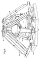
- a coordinate measuring machine is shown in Fig 1.
- the coordinate measuring machine comprises a lower fixed stage 10 and an upper movable stage 12.
- the upper and lower stages are linked by telescopic struts 14, each strut being connected to the upper and lower stages at its respective upper and lower ends by pivot joints.
- Each strut has a motor 16 to increase or decrease its length.
- this stage may rotate about three perpendicular axes relative to the lower stage 10.
- three anti-rotational devices 20 are provided which eliminate these three degrees of rotational freedom whilst allowing translational movement.
- the devices are passive, i.e. they have no motor or other actuator.
- the joints between the anti-rotational devices 20 and the upper and lower stages 12,10 are also pivot joints.
- a pivot joint between the upper stage 12 and an anti-rotational device 20 is shown in more detail in Figs 2,4 and 5.
- the upper stage 12 is provided with structured cut-outs 30.
- a ball 32 of the pivot joint is supported within the cut-out 30 by surfaces defining the periphery of the cut-out 30.
- Two cut-outs 30 are shown in Fig 2, one with the other components of the ball joint in place and the other without.
- the ball 32 is supported by two opposite surfaces 34,36 of the cut-out 30.
- a first curved surface 34 contacts a side of the ball 32, and a second curved surface 36 contacts a lower surface of the ball 32 with two points of contact 36A, 36B.
- the position of the ball 32 is defined by these three points of contact 34,36A,36B and a fourth point of contact provided by a clamp 38,42.
- the clamp comprises a washer 38 and a fixing device 42, such as a screw or bolt.
- the washer 38 sits on a shelf 41 provided in the cut-out 30 in the upper stage 12, an edge of its lower surface in contact with the ball 32.
- the upper stage 12 is provided with a hole 40 aligned with the centre of the washer 38, to receive the fixing device 42 which holds the washer 38 against the ball 32.
- the ball 32 is thus held rigidly in a fixed position at four places around its surface by the first curved surface 34, by two points of contact 36A, 36B on the second curved surface 36, and by the washer 38.
- FIG 9 An alternative pivot joint between the upper stage 12 and a strut 14 is shown in Fig 9.
- the upper stage 12 is provided with structured cut-outs 130.
- a ball 32 of the pivot joint is supported within the cut-out 130 by surfaces defining the periphery of the cut-out 130.
- Two cut-outs 130 are shown in Fig 9, one with the other components of the ball joint in place and the other without.
- the ball 32 is supported by two opposite surfaces 134,136 of the cut-out 130.
- a first curved surface 134 contacts a lower surface of the ball 32, and a second curved surface 136 contacts a side of the ball 32 with two points of contact 136A,136B.
- the position of the ball 32 is defined by these three points of contact 134,136A,136B and a fourth point of contact provided by a clamp 38,42.
- Each end of each of the telescopic struts 14 and anti-rotational devices 20 is provided with a hole 45 which fits over a ball 32 of a respective pivot joint.
- Each hole 45 is shaped to have three bearing surfaces 43A,B,C, spaced at 120° apart, as shown in Fig 3. Only the three bearing surfaces are in contact with the ball 32. These bearing surfaces have small areas of contact with the ball 32 to maximise slide between the surfaces. These small areas of contact also provide repeatable positioning of the strut 14 or anti-rotational device 20 with respect to the ball 32.
- the second structure 14,20 encircling the ball 32
- the second structure may substantially encircle the ball with a gap in the structure (the limiting size of any gap is a function of the diameter of the ball and the position of the bearing surfaces of the second structure).
- both the struts 14 and anti-rotational devices 20 have pivot joints according to the invention, this is not essential.
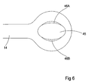
- Fig 6 shows an alternative arrangement of the bearing surfaces.
- the hole 45 is oval with only two bearing surfaces 46A, 46B.
- This arrangement is particularly suitable when the force on the bearing surface is parallel to an axis perpendicular to the plane of the bearing surfaces (for example if the ball joint is used in a jack).
- the struts 14 and anti-rotational devices 20 are formed from a good bearing material, such as phosphor bronze.
- the strut 14 may be made by etching and then machining or stamping the holes 45 to accurately control the length and geometry of the holes 45.
- FIG 5 is a section along line A-A of Fig 4.
- the ball 32 can be seen to be held in position by three of the four points of contact. These are the first curved surfaces 34 and two points of contact on the second curved surface 36 provided on the stage 12 and the surface 37 of the washer 38. These surfaces are shown to be spaced around the circumference of the ball 32.
- the surface 37 of washer 38 in contact with the ball 32 is a chamfered edge between the lower and side surfaces of the washer 38 and extends all around the circumference of the washer 38 so that this surface 37 is presented to the ball 32 whatever the orientation of the washer 38.
- the structured cut-outs 30 each have cut-out lobes 31 either side of the ball 32 to allow enough room for the end of the anti-rotational device 20 to manoeuvre.
- the three bearing surfaces 43A,B,C remain in contact with the ball yet move over the ball to allow the arm of the anti-rotational device 20 to rotate about the ball 32.
- An alternative way of urging the bearing surfaces onto the ball 32 is by biasing the second structure 14,20.
- One way to achieve this is to provide a plate which has one end clamped to the second structure 14,20 and the other end pressing against the ball 32.
- the plate thus acts like a leaf spring.
- the clamp is preferably removably fixed by, for example, a screw, to enable removal of the ball 32 for maintenance or replacement thereof.
- the word plate is intended to include all the various shapes and structures that are suitable for providing a bias such as a washer. Such a plate could be used in conjunction with washer 38 or as a replacement.
- the ball used in the pivot joint may be made of any hard/low friction material or alternatively made of any material coated with a hard/low friction material.
- pivot joint in a coordinate measuring machine
- this pivot joint is not limited to use with such machines and may be used in other applications.
- the invention is not limited to the method of locating a ball as described above.
- the embodiment describes four points of contact with the ball, one of which is adjustable, it is possible to have more than a total of four points of contact with the ball. In addition it is possible to have more than one adjustable point of contact, for example all four points of contact could be adjustable.
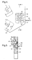
- FIG 7. An alternative method of clamping a ball rigidly in a precise location is shown in Fig 7.
- the ball 32 is located in a conical recess 48 and held in place by a securing device 52 (for example a screw) with one point of contact 54 with the ball 32.
- a securing device 52 for example a screw
- the securing device 52 may have more than one point of contact with the ball 32 (for example a v-groove).
- Fig 8 shows another method of clamping a ball rigidly in a precise location.
- the ball 32 is located on a flat surface 50 and is held in place by a securing device 52 which has a conical recess 56 in contact with the surface of the ball 32.
- the ball may also be held in position by permanent methods such as bonding, braising and welding. However these methods have the disadvantage that the ball is then no longer replaceable.
- This pivot joint has the advantages that it is both cheap to manufacture and easy to assemble.
- the cut-out structure which holds the ball is easy to machine. Repeatable positioning of a free ball within this structure enables the ball to be easily replaced. Furthermore use of commercially available accurate spheres (for example ball bearings) combined with precise positioning in the structure produces a high precision ball joint.
- pivot joint throughout this specification is defined as including pivot joints with one, two and three degrees of freedom as well as universal joints having two or three degrees of freedom.
Landscapes
- Engineering & Computer Science (AREA)
- General Engineering & Computer Science (AREA)
- Mechanical Engineering (AREA)
- Physics & Mathematics (AREA)
- General Physics & Mathematics (AREA)
- Pivots And Pivotal Connections (AREA)
- Acyclic And Carbocyclic Compounds In Medicinal Compositions (AREA)
- Non-Disconnectible Joints And Screw-Threaded Joints (AREA)
- Pharmaceuticals Containing Other Organic And Inorganic Compounds (AREA)
Priority Applications (1)
| Application Number | Priority Date | Filing Date | Title |
|---|---|---|---|
| EP07002282A EP1777423B1 (en) | 2001-07-13 | 2002-07-15 | Pivot joint |
Applications Claiming Priority (3)
| Application Number | Priority Date | Filing Date | Title |
|---|---|---|---|
| GBGB0117098.4A GB0117098D0 (en) | 2001-07-13 | 2001-07-13 | Pivot joint |
| GB0117098 | 2001-07-13 | ||
| PCT/GB2002/003294 WO2003006837A1 (en) | 2001-07-13 | 2002-07-15 | Pivot joint |
Related Child Applications (2)
| Application Number | Title | Priority Date | Filing Date |
|---|---|---|---|
| EP07002282A Division EP1777423B1 (en) | 2001-07-13 | 2002-07-15 | Pivot joint |
| EP06020367 Division | 2006-09-28 |
Publications (2)
| Publication Number | Publication Date |
|---|---|
| EP1407152A1 EP1407152A1 (en) | 2004-04-14 |
| EP1407152B1 true EP1407152B1 (en) | 2007-03-21 |
Family
ID=9918426
Family Applications (2)
| Application Number | Title | Priority Date | Filing Date |
|---|---|---|---|
| EP02749025A Expired - Lifetime EP1407152B1 (en) | 2001-07-13 | 2002-07-15 | Pivot joint |
| EP07002282A Expired - Lifetime EP1777423B1 (en) | 2001-07-13 | 2002-07-15 | Pivot joint |
Family Applications After (1)
| Application Number | Title | Priority Date | Filing Date |
|---|---|---|---|
| EP07002282A Expired - Lifetime EP1777423B1 (en) | 2001-07-13 | 2002-07-15 | Pivot joint |
Country Status (8)
| Country | Link |
|---|---|
| EP (2) | EP1407152B1 (enExample) |
| JP (2) | JP2004534189A (enExample) |
| CN (1) | CN100402873C (enExample) |
| AT (2) | ATE357609T1 (enExample) |
| DE (2) | DE60231160D1 (enExample) |
| ES (1) | ES2320810T3 (enExample) |
| GB (1) | GB0117098D0 (enExample) |
| WO (1) | WO2003006837A1 (enExample) |
Cited By (1)
| Publication number | Priority date | Publication date | Assignee | Title |
|---|---|---|---|---|
| WO2020077446A1 (en) * | 2018-10-15 | 2020-04-23 | North Rim Investment Group Ltd. | Supports and securements for cameras, lighting and other equipment, and novel couplers and accessories for same |
Families Citing this family (9)
| Publication number | Priority date | Publication date | Assignee | Title |
|---|---|---|---|---|
| WO2004063579A1 (en) * | 2003-01-15 | 2004-07-29 | Renishaw Plc | Pivot joint |
| GB201113715D0 (en) | 2011-08-09 | 2011-09-21 | Renishaw Plc | Method and apparatus for inspecting workpieces |
| GB201308467D0 (en) | 2013-05-10 | 2013-06-19 | Renishaw Plc | Method and Apparatus for Inspecting Workpieces |
| CN104033481A (zh) * | 2014-06-20 | 2014-09-10 | 浙江瑞朗锻造有限公司 | 曲形拉杆球壳 |
| GB201513850D0 (en) * | 2015-08-05 | 2015-09-16 | Renishaw Plc | Coordinate positioning machine |
| GB201515171D0 (en) | 2015-08-26 | 2015-10-07 | Renishaw Plc | Braking system |
| EP3440426B1 (en) | 2016-04-08 | 2021-06-30 | Renishaw PLC | Coordinate positioning machine |
| GB2568459B (en) | 2017-10-13 | 2020-03-18 | Renishaw Plc | Coordinate positioning machine |
| GB2582972B (en) | 2019-04-12 | 2021-07-14 | Renishaw Plc | Coordinate positioning machine |
Family Cites Families (17)
| Publication number | Priority date | Publication date | Assignee | Title |
|---|---|---|---|---|
| FR947212A (fr) * | 1947-05-24 | 1949-06-27 | Specialites R A V E L | Articulation universelle |
| US3490798A (en) * | 1968-09-27 | 1970-01-20 | Rudolf A Spyra | Ball-and-socket coupling |
| JPS5135852A (en) * | 1974-09-20 | 1976-03-26 | Hiroshi Teramachi | Konekutobooru oyobi sonoseiho |
| JPS5159744U (enExample) * | 1974-11-05 | 1976-05-11 | ||
| JPS591924U (ja) * | 1982-06-28 | 1984-01-07 | 日野自動車株式会社 | 自在継手 |
| JPS636211A (ja) * | 1986-06-27 | 1988-01-12 | Hiroshi Teramachi | ボ−ルジヨイント及びその製造法 |
| JPS63303226A (ja) * | 1987-05-30 | 1988-12-09 | Toshiharu Fujita | 自在継手 |
| GB2205146B (en) * | 1987-05-30 | 1990-12-05 | Sanyu Co Ltd | Universal joint |
| JPH0374776U (enExample) * | 1989-11-09 | 1991-07-26 | ||
| DE4333913C2 (de) * | 1992-10-09 | 1997-11-20 | Link Johs Sonor Gmbh | Einstellvorrichtung an längen- und/oder neigungsverstellbaren Haltern, insbesondere für Percussions-Musikinstrumente |
| US5568993A (en) * | 1994-12-21 | 1996-10-29 | The United States Of America As Represented By The Secretary Of Commerce | Strut structure and rigid joint therefor |
| JP3275609B2 (ja) * | 1995-02-21 | 2002-04-15 | 日立電線株式会社 | 電線把持装置 |
| JP2614430B2 (ja) * | 1995-06-12 | 1997-05-28 | 和也 廣瀬 | 球面軸受 |
| US5704578A (en) * | 1995-11-03 | 1998-01-06 | Jbl Incorporated | Front-locking swivel ball loudspeaker mount |
| JPH09210049A (ja) * | 1996-02-01 | 1997-08-12 | Toyota Motor Corp | マニュアル式シフトレバーの連結構造 |
| DE19921148A1 (de) * | 1999-05-07 | 2000-11-09 | Hilti Ag | Schienenfuß für ein Diamantschneidesystem |
| DE19938242C1 (de) * | 1999-08-12 | 2001-06-21 | Gutjahr Gmbh | Kugelspannvorrichtung |
-
2001
- 2001-07-13 GB GBGB0117098.4A patent/GB0117098D0/en not_active Ceased
-
2002
- 2002-07-15 CN CNB028141202A patent/CN100402873C/zh not_active Expired - Fee Related
- 2002-07-15 AT AT02749025T patent/ATE357609T1/de not_active IP Right Cessation
- 2002-07-15 WO PCT/GB2002/003294 patent/WO2003006837A1/en not_active Ceased
- 2002-07-15 AT AT07002282T patent/ATE422623T1/de not_active IP Right Cessation
- 2002-07-15 DE DE60231160T patent/DE60231160D1/de not_active Expired - Lifetime
- 2002-07-15 EP EP02749025A patent/EP1407152B1/en not_active Expired - Lifetime
- 2002-07-15 JP JP2003512568A patent/JP2004534189A/ja active Pending
- 2002-07-15 ES ES07002282T patent/ES2320810T3/es not_active Expired - Lifetime
- 2002-07-15 DE DE60219018T patent/DE60219018T2/de not_active Expired - Lifetime
- 2002-07-15 EP EP07002282A patent/EP1777423B1/en not_active Expired - Lifetime
-
2009
- 2009-12-14 JP JP2009282732A patent/JP5546842B2/ja not_active Expired - Fee Related
Cited By (1)
| Publication number | Priority date | Publication date | Assignee | Title |
|---|---|---|---|---|
| WO2020077446A1 (en) * | 2018-10-15 | 2020-04-23 | North Rim Investment Group Ltd. | Supports and securements for cameras, lighting and other equipment, and novel couplers and accessories for same |
Also Published As
| Publication number | Publication date |
|---|---|
| GB0117098D0 (en) | 2001-09-05 |
| DE60231160D1 (de) | 2009-03-26 |
| ATE422623T1 (de) | 2009-02-15 |
| JP2010065849A (ja) | 2010-03-25 |
| WO2003006837A1 (en) | 2003-01-23 |
| JP5546842B2 (ja) | 2014-07-09 |
| CN1527910A (zh) | 2004-09-08 |
| EP1777423A1 (en) | 2007-04-25 |
| ES2320810T3 (es) | 2009-05-28 |
| DE60219018T2 (de) | 2007-12-13 |
| ATE357609T1 (de) | 2007-04-15 |
| EP1777423B1 (en) | 2009-02-11 |
| JP2004534189A (ja) | 2004-11-11 |
| CN100402873C (zh) | 2008-07-16 |
| DE60219018D1 (de) | 2007-05-03 |
| EP1407152A1 (en) | 2004-04-14 |
Similar Documents
| Publication | Publication Date | Title |
|---|---|---|
| US8074369B2 (en) | Pivot joint | |
| JP5546842B2 (ja) | 座標測定機械 | |
| EP2108488B1 (en) | Parallel mechanism with improved ball and socket joints | |
| US20110070019A1 (en) | Joint | |
| US20120139278A1 (en) | Flexible adjustable gripping device | |
| US6129476A (en) | Breakaway precision robot end effector | |
| US20110113918A1 (en) | Translational branch joint and parallel robot utilizing the same | |
| US8469830B2 (en) | Universal joint | |
| JPS63102856A (ja) | 第1の物体の第2の物体に対する相対的な位置を再現可能に高精度で定めるための装置 | |
| JP4851716B2 (ja) | ピボットジョイント | |
| JP6938693B2 (ja) | ジョイント | |
| JPH055389U (ja) | フローテイングハンド | |
| WO2014178202A1 (ja) | 球面ジョイント機構及びこの球面ジョイント機構を備えた組立て装置 | |
| US6231433B1 (en) | Blank clamping device for a machine for trimming optical lenses | |
| WO2009027660A2 (en) | Pivot joint assembly | |
| CN210285906U (zh) | 一种夹具工装存放机构 | |
| JP4011332B2 (ja) | 面合わせ装置 | |
| CN222609563U (zh) | 平台组件、六自由度平台及穿戴设备制造装置 | |
| US20250379529A1 (en) | X-shaped ultrasonic motor and robotic arm | |
| JPH08141970A (ja) | 産業用ロボットの工具取付装置 | |
| JPH03178725A (ja) | フローティングホルダ | |
| JPH07122455B2 (ja) | 精密位置決め装置 | |
| JPH0588776U (ja) | 位置決め装置 | |
| JPH05162032A (ja) | 位置合わせ機構 | |
| CN115255687A (zh) | 一种用于激光焊接的激光镜组焦点标定装置 |
Legal Events
| Date | Code | Title | Description |
|---|---|---|---|
| PUAI | Public reference made under article 153(3) epc to a published international application that has entered the european phase |
Free format text: ORIGINAL CODE: 0009012 |
|
| 17P | Request for examination filed |
Effective date: 20040112 |
|
| AK | Designated contracting states |
Kind code of ref document: A1 Designated state(s): AT BE BG CH CY CZ DE DK EE ES FI FR GB GR IE IT LI LU MC NL PT SE SK TR |
|
| AX | Request for extension of the european patent |
Extension state: AL LT LV MK RO SI |
|
| GRAP | Despatch of communication of intention to grant a patent |
Free format text: ORIGINAL CODE: EPIDOSNIGR1 |
|
| GRAS | Grant fee paid |
Free format text: ORIGINAL CODE: EPIDOSNIGR3 |
|
| GRAA | (expected) grant |
Free format text: ORIGINAL CODE: 0009210 |
|
| AK | Designated contracting states |
Kind code of ref document: B1 Designated state(s): AT BE BG CH CY CZ DE DK EE ES FI FR GB GR IE IT LI LU MC NL PT SE SK TR |
|
| PG25 | Lapsed in a contracting state [announced via postgrant information from national office to epo] |
Ref country code: FI Free format text: LAPSE BECAUSE OF FAILURE TO SUBMIT A TRANSLATION OF THE DESCRIPTION OR TO PAY THE FEE WITHIN THE PRESCRIBED TIME-LIMIT Effective date: 20070321 Ref country code: AT Free format text: LAPSE BECAUSE OF FAILURE TO SUBMIT A TRANSLATION OF THE DESCRIPTION OR TO PAY THE FEE WITHIN THE PRESCRIBED TIME-LIMIT Effective date: 20070321 Ref country code: NL Free format text: LAPSE BECAUSE OF FAILURE TO SUBMIT A TRANSLATION OF THE DESCRIPTION OR TO PAY THE FEE WITHIN THE PRESCRIBED TIME-LIMIT Effective date: 20070321 Ref country code: BE Free format text: LAPSE BECAUSE OF FAILURE TO SUBMIT A TRANSLATION OF THE DESCRIPTION OR TO PAY THE FEE WITHIN THE PRESCRIBED TIME-LIMIT Effective date: 20070321 |
|
| REG | Reference to a national code |
Ref country code: GB Ref legal event code: FG4D |
|
| REG | Reference to a national code |
Ref country code: CH Ref legal event code: EP |
|
| REF | Corresponds to: |
Ref document number: 60219018 Country of ref document: DE Date of ref document: 20070503 Kind code of ref document: P |
|
| REG | Reference to a national code |
Ref country code: IE Ref legal event code: FG4D |
|
| REG | Reference to a national code |
Ref country code: CH Ref legal event code: NV Representative=s name: KIRKER & CIE S.A. |
|
| PG25 | Lapsed in a contracting state [announced via postgrant information from national office to epo] |
Ref country code: SE Free format text: LAPSE BECAUSE OF FAILURE TO SUBMIT A TRANSLATION OF THE DESCRIPTION OR TO PAY THE FEE WITHIN THE PRESCRIBED TIME-LIMIT Effective date: 20070621 |
|
| PG25 | Lapsed in a contracting state [announced via postgrant information from national office to epo] |
Ref country code: ES Free format text: LAPSE BECAUSE OF FAILURE TO SUBMIT A TRANSLATION OF THE DESCRIPTION OR TO PAY THE FEE WITHIN THE PRESCRIBED TIME-LIMIT Effective date: 20070702 |
|
| ET | Fr: translation filed | ||
| PG25 | Lapsed in a contracting state [announced via postgrant information from national office to epo] |
Ref country code: PT Free format text: LAPSE BECAUSE OF FAILURE TO SUBMIT A TRANSLATION OF THE DESCRIPTION OR TO PAY THE FEE WITHIN THE PRESCRIBED TIME-LIMIT Effective date: 20070821 |
|
| NLV1 | Nl: lapsed or annulled due to failure to fulfill the requirements of art. 29p and 29m of the patents act | ||
| PG25 | Lapsed in a contracting state [announced via postgrant information from national office to epo] |
Ref country code: SK Free format text: LAPSE BECAUSE OF FAILURE TO SUBMIT A TRANSLATION OF THE DESCRIPTION OR TO PAY THE FEE WITHIN THE PRESCRIBED TIME-LIMIT Effective date: 20070321 |
|
| PG25 | Lapsed in a contracting state [announced via postgrant information from national office to epo] |
Ref country code: CZ Free format text: LAPSE BECAUSE OF FAILURE TO SUBMIT A TRANSLATION OF THE DESCRIPTION OR TO PAY THE FEE WITHIN THE PRESCRIBED TIME-LIMIT Effective date: 20070321 |
|
| PLBE | No opposition filed within time limit |
Free format text: ORIGINAL CODE: 0009261 |
|
| STAA | Information on the status of an ep patent application or granted ep patent |
Free format text: STATUS: NO OPPOSITION FILED WITHIN TIME LIMIT |
|
| PG25 | Lapsed in a contracting state [announced via postgrant information from national office to epo] |
Ref country code: DK Free format text: LAPSE BECAUSE OF FAILURE TO SUBMIT A TRANSLATION OF THE DESCRIPTION OR TO PAY THE FEE WITHIN THE PRESCRIBED TIME-LIMIT Effective date: 20070321 |
|
| 26N | No opposition filed |
Effective date: 20071227 |
|
| PG25 | Lapsed in a contracting state [announced via postgrant information from national office to epo] |
Ref country code: MC Free format text: LAPSE BECAUSE OF NON-PAYMENT OF DUE FEES Effective date: 20070731 Ref country code: GR Free format text: LAPSE BECAUSE OF FAILURE TO SUBMIT A TRANSLATION OF THE DESCRIPTION OR TO PAY THE FEE WITHIN THE PRESCRIBED TIME-LIMIT Effective date: 20070622 |
|
| PG25 | Lapsed in a contracting state [announced via postgrant information from national office to epo] |
Ref country code: IE Free format text: LAPSE BECAUSE OF NON-PAYMENT OF DUE FEES Effective date: 20070716 |
|
| PG25 | Lapsed in a contracting state [announced via postgrant information from national office to epo] |
Ref country code: EE Free format text: LAPSE BECAUSE OF FAILURE TO SUBMIT A TRANSLATION OF THE DESCRIPTION OR TO PAY THE FEE WITHIN THE PRESCRIBED TIME-LIMIT Effective date: 20070321 |
|
| PG25 | Lapsed in a contracting state [announced via postgrant information from national office to epo] |
Ref country code: CY Free format text: LAPSE BECAUSE OF FAILURE TO SUBMIT A TRANSLATION OF THE DESCRIPTION OR TO PAY THE FEE WITHIN THE PRESCRIBED TIME-LIMIT Effective date: 20070321 |
|
| PG25 | Lapsed in a contracting state [announced via postgrant information from national office to epo] |
Ref country code: LU Free format text: LAPSE BECAUSE OF NON-PAYMENT OF DUE FEES Effective date: 20070715 Ref country code: BG Free format text: LAPSE BECAUSE OF FAILURE TO SUBMIT A TRANSLATION OF THE DESCRIPTION OR TO PAY THE FEE WITHIN THE PRESCRIBED TIME-LIMIT Effective date: 20070621 |
|
| PG25 | Lapsed in a contracting state [announced via postgrant information from national office to epo] |
Ref country code: TR Free format text: LAPSE BECAUSE OF FAILURE TO SUBMIT A TRANSLATION OF THE DESCRIPTION OR TO PAY THE FEE WITHIN THE PRESCRIBED TIME-LIMIT Effective date: 20070321 |
|
| PGFP | Annual fee paid to national office [announced via postgrant information from national office to epo] |
Ref country code: CH Payment date: 20130719 Year of fee payment: 12 |
|
| REG | Reference to a national code |
Ref country code: CH Ref legal event code: PL |
|
| PG25 | Lapsed in a contracting state [announced via postgrant information from national office to epo] |
Ref country code: LI Free format text: LAPSE BECAUSE OF NON-PAYMENT OF DUE FEES Effective date: 20140731 Ref country code: CH Free format text: LAPSE BECAUSE OF NON-PAYMENT OF DUE FEES Effective date: 20140731 |
|
| REG | Reference to a national code |
Ref country code: FR Ref legal event code: PLFP Year of fee payment: 15 |
|
| PGFP | Annual fee paid to national office [announced via postgrant information from national office to epo] |
Ref country code: GB Payment date: 20160721 Year of fee payment: 15 Ref country code: IT Payment date: 20160727 Year of fee payment: 15 |
|
| PGFP | Annual fee paid to national office [announced via postgrant information from national office to epo] |
Ref country code: FR Payment date: 20160721 Year of fee payment: 15 |
|
| GBPC | Gb: european patent ceased through non-payment of renewal fee |
Effective date: 20170715 |
|
| REG | Reference to a national code |
Ref country code: FR Ref legal event code: ST Effective date: 20180330 |
|
| PG25 | Lapsed in a contracting state [announced via postgrant information from national office to epo] |
Ref country code: GB Free format text: LAPSE BECAUSE OF NON-PAYMENT OF DUE FEES Effective date: 20170715 |
|
| PG25 | Lapsed in a contracting state [announced via postgrant information from national office to epo] |
Ref country code: FR Free format text: LAPSE BECAUSE OF NON-PAYMENT OF DUE FEES Effective date: 20170731 |
|
| PG25 | Lapsed in a contracting state [announced via postgrant information from national office to epo] |
Ref country code: IT Free format text: LAPSE BECAUSE OF NON-PAYMENT OF DUE FEES Effective date: 20170715 |
|
| PGFP | Annual fee paid to national office [announced via postgrant information from national office to epo] |
Ref country code: DE Payment date: 20200928 Year of fee payment: 19 |
|
| REG | Reference to a national code |
Ref country code: DE Ref legal event code: R119 Ref document number: 60219018 Country of ref document: DE |
|
| PG25 | Lapsed in a contracting state [announced via postgrant information from national office to epo] |
Ref country code: DE Free format text: LAPSE BECAUSE OF NON-PAYMENT OF DUE FEES Effective date: 20220201 |