EP1405976A1 - Türe mit verschiebbarem Türblatt und mit Führungsmitteln - Google Patents
Türe mit verschiebbarem Türblatt und mit Führungsmitteln Download PDFInfo
- Publication number
- EP1405976A1 EP1405976A1 EP03021881A EP03021881A EP1405976A1 EP 1405976 A1 EP1405976 A1 EP 1405976A1 EP 03021881 A EP03021881 A EP 03021881A EP 03021881 A EP03021881 A EP 03021881A EP 1405976 A1 EP1405976 A1 EP 1405976A1
- Authority
- EP
- European Patent Office
- Prior art keywords
- door
- guide
- door leaf
- band
- guide surface
- Prior art date
- Legal status (The legal status is an assumption and is not a legal conclusion. Google has not performed a legal analysis and makes no representation as to the accuracy of the status listed.)
- Withdrawn
Links
- 238000006073 displacement reaction Methods 0.000 claims description 17
- 238000007789 sealing Methods 0.000 claims description 8
- 230000033001 locomotion Effects 0.000 abstract description 13
- 239000000463 material Substances 0.000 description 10
- 239000013013 elastic material Substances 0.000 description 4
- 230000000694 effects Effects 0.000 description 3
- 238000011161 development Methods 0.000 description 2
- 230000018109 developmental process Effects 0.000 description 2
- 238000005457 optimization Methods 0.000 description 2
- 239000004677 Nylon Substances 0.000 description 1
- 239000004809 Teflon Substances 0.000 description 1
- 229920006362 Teflon® Polymers 0.000 description 1
- 238000011109 contamination Methods 0.000 description 1
- 230000001419 dependent effect Effects 0.000 description 1
- 239000000446 fuel Substances 0.000 description 1
- 238000009434 installation Methods 0.000 description 1
- 239000000203 mixture Substances 0.000 description 1
- 229920001778 nylon Polymers 0.000 description 1
- 230000036316 preload Effects 0.000 description 1
- 238000005096 rolling process Methods 0.000 description 1
- 239000000565 sealant Substances 0.000 description 1
- 238000000926 separation method Methods 0.000 description 1
- 238000007493 shaping process Methods 0.000 description 1
- 239000000779 smoke Substances 0.000 description 1
- 230000003068 static effect Effects 0.000 description 1
- 239000000725 suspension Substances 0.000 description 1
Images


Classifications
-
- E—FIXED CONSTRUCTIONS
- E05—LOCKS; KEYS; WINDOW OR DOOR FITTINGS; SAFES
- E05D—HINGES OR SUSPENSION DEVICES FOR DOORS, WINDOWS OR WINGS
- E05D15/00—Suspension arrangements for wings
- E05D15/06—Suspension arrangements for wings for wings sliding horizontally more or less in their own plane
- E05D15/0621—Details, e.g. suspension or supporting guides
- E05D15/0626—Details, e.g. suspension or supporting guides for wings suspended at the top
- E05D15/0656—Bottom guides
-
- E—FIXED CONSTRUCTIONS
- E05—LOCKS; KEYS; WINDOW OR DOOR FITTINGS; SAFES
- E05Y—INDEXING SCHEME ASSOCIATED WITH SUBCLASSES E05D AND E05F, RELATING TO CONSTRUCTION ELEMENTS, ELECTRIC CONTROL, POWER SUPPLY, POWER SIGNAL OR TRANSMISSION, USER INTERFACES, MOUNTING OR COUPLING, DETAILS, ACCESSORIES, AUXILIARY OPERATIONS NOT OTHERWISE PROVIDED FOR, APPLICATION THEREOF
- E05Y2900/00—Application of doors, windows, wings or fittings thereof
- E05Y2900/10—Application of doors, windows, wings or fittings thereof for buildings or parts thereof
- E05Y2900/13—Type of wing
- E05Y2900/132—Doors
Definitions
- the invention relates to a door with a sliding Door leaf according to the preamble of claim 1 and one Elevator system with such a door.
- Doors with sliding door leaves which also as Sliding doors are called, have numerous advantages on; in particular, their space requirement compared to that Space requirements for swinging doors are comparatively small, as the opening door leaves parallel and in immediate Move close to the wall and therefore no accessible space in the Claim the area of the door opening.
- an elevator installation with a appropriately guided door provided.
- the door according to the invention basically has two components on, namely a sliding door leaf and a component that a guide surface for guiding the door leaf at a Provides displacement, for example a door frame or door frame-like component, simplifying in the following is called a frame.
- the door leaf is in one Direction of displacement back and forth relative to the frame displaceable.
- management means for the management of the Door leaf provided for its lateral displacement.
- These guide means are located in the area of an edge of the Door leaf, which changes when the door leaf is moved moved along an adjacent part of the frame.
- the Guide means essentially consist of a band.
- the Band is arranged so that it moves Door leaf follows, whereby during the displacement of the Door leaf a section of the hinge on the guide surface is applied.
- the tape is aligned so that it is with its band length along the guide surface for the door leaf extends.
- One surface of the tape lies open, itself sliding and closed door leaf on the Leadership area.
- one or more guide elements may be used to provide for the tape to the tape on the guide surface align.
- the tape is aligned by the guide elements so that a Section of the tape abuts the guide surface and that Band runs around at least one of the guide elements.
- the guide means guide the door leaf along the Guide surface and give it stability.
- the guide means can be designed such that they serve as a sealant. This is particularly the case with Landing doors of an elevator are an advantage as they are in the Elevator shaft often gives a negative or positive pressure that causes air to flow through the shaft doors. Next the fact that such air currents are considered uncomfortable can also be perceived as disturbing Sounds. In elevator systems with fast moving Elevators sometimes have such large pressure differences that the door leaves only close a shaft door with great force are open. Such conditions can with the guide elements according to the invention can be avoided.
- a band used with elastic properties In the door according to the invention is preferably a band used with elastic properties.
- a tape with elastic properties should be in the frame of the invention tapes are understood that in Belt longitudinal direction and / or belt transverse direction and / or transverse to Band surface are elastic.
- tapes that are in Longitudinal tape direction are elastic, do not have to or not be made entirely of elastic materials; she can also have one or more sections from practical have non-elastic material made by sections elastic material are connected, or by means of practically non-elastic links variable in length are interconnected.
- Tapes when used with Moving the door leaf is not just a guide of the Door leaf and a noise reduction but also one Sealing with the door closed is intended in Generally elastic in the direction transverse to the band surface compressible; what is meant by it from are made of elastically compressible material; you can but also made of elastic, but practically incompressible Material be made when shaping for example with two connected legs, which can be brought elastically to one another in the direction transverse to the band surface are.
- the tapes used must be one Have flexibility that allows them to be around To let guide elements circulate.
- they are Guide elements of the guide means on the frame or in the area of the frame arranged while the guide surface on Door leaf is located in the area of its edge.
- the guide elements have or several, preferably two deflecting elements on the the part of the door that is not attached Has guide surface.
- the band can be an endless band or be designed as an open band with two band ends.
- endless Tapes can have at least one tape point in one The anchor point of the component of the door must be anchored to the Has guide surface; open tapes can with each at least one band position in the area of their band ends in be anchored in the anchorage area Guide surface is located.
- an open band with two Band ends used.
- a first end of the band is at one Band position anchored stationary in an anchor point that is located in the area of the guide surface; the second end of the tape is on a first guide element, which is a longitudinal guide forms, led.
- the tape runs between the attached Band point and the longitudinal guide around the second Guide element which is formed by a deflecting body.
- the door leaf can be moved laterally and in hung its upper part; that edge of the Door leaf, in the area of which the guide means is then the lower edge of the door leaf.
- the door leaf can also be in the vertical direction be movable; this can then guide means in The meaning of the invention in the area of one or both lateral Edges of the door leaf may be provided.
- the door leaf can do that single door leaf or part of a door system several backdrop-like sliding door leaves.
- the band surface and the guide surface on which the band surface abuts can be designed so that between them either a little slip is possible, or that everyone Slip is prevented.
- a relative slip can can be prevented by touching the surfaces suitable profile with profile surfaces across Have direction of displacement (positive connection), or by applying sufficient pressure to the belt surface at the Contact surface or by choosing materials, which ensure sufficient adhesion.
- At least one of the Guide elements across the door leaf and across the Direction of displacement of the door leaf can be moved elastically to arrange. With such an arrangement, it is possible that Band with a preload caused by the position of the elastically displaceable guide element is controllable, to keep in contact with the guide surface.
- At least one of the guide elements can by at least a rotatable roller can be formed, the slide bearing or Rolling bearing is connected to the door leaf.
- a guide element can also have multiple roles, and it can be a load balancing element in the form of a Secondary belt can be provided, which rotates around these roles and is arranged between the belt and the guide element.
- the hinge can, especially if the door leaf is in Closing position is in the direction of the guide surface be preloaded to a sealing body between the Form guide surface and a surface of the door leaf.
- the door can have a further guide surface and further guide means which are arranged such that the door is guided transversely to the door leaf in both directions. In this way, a guidance of the door leaf can be realized which is free of play transversely to the direction of movement. A door with a door leaf that is guided with little or no play can be sealed particularly effectively since zones in the area of the guide that are permeable to air can be largely reduced or even avoided.
- a first embodiment of the invention is related 1A to 1C.
- a door 10 is shown which forms a shaft door of an elevator.
- the door 10 has at least one frame 19 and a door leaf 11, the in a direction of displacement 12 relative to the frame 19 is movable.
- On the frame 19 is a vertical one Guide surface 18 arranged (see Fig. 1C) on which the Door leaf 11 is to be performed.
- the door 10 has guide means on in the region of the lower edge 16 of the door leaf 11 are arranged.
- the leadership means include a (Elastic) band 13 and guide elements 14 and 15, the Door leaf 11 are arranged and around which the band 13 rotates.
- the band 13 is so through the guide elements 14, 15 aligned that it is parallel to the tape length Direction of displacement 12 of the door leaf 11 extends.
- a The area of the belt 13 is when the door is open, closed and sliding door leaf 11 flat on the guide surface 18 on.
- the door leaf 11 in the upper door area to have a suspension.
- Fig. 1C is a schematic section of this Embodiment shown. Below the area of the door leaf soul or door leaf middle surface is in the frame 19, or in Area of the frame, a groove provided in the illustrated embodiment a rectangular Cross section. A vertical side surface of this groove forms the guide surface 18.
- the guide elements 14, 15 are attached by which the guide element 14 is visible in Fig. 1C. in the 1C is the elastic band 13, or the Guide element 14 surrounding part of this band 13, too see.
- the part of the surface facing the guide surface 18 The outer surface of the band 13 lies against the guide surface 18, during that part of the surface facing away from the guide surface 18
- the outer surface of the belt 13 is free and essentially runs without contact.
- the inner surface of the band 13 is for Touch of the guide elements 14, 15 determined.
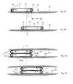
- the mode of operation of the arrangement according to the invention is based 2A and 2B on the principle of a Vehicle chain related to locomotion, Example of a tracked vehicle is used.
- Volume 23 moves in a way like the vehicle chain.
- the guide elements 24, 25 move in solidarity with the Door leaf 21.
- the one lying against the guide surface 28 Part of the belt 23 remains during the displacement of the Door leaf 21 substantially stationary.
- fasteners e.g. axles or Screws
- the guide means do that Door leaf 21; they give the door leaf 21 stability, and they reduce or prevent movement of the door leaf 21 across the door leaf surface and across the direction of movement its horizontal shift.
- this is Leadership only one-sided.
- a guide on both sides can be used an arrangement according to FIGS. 3A and 3B can be achieved.
- the door points in the direction of Arrow 32 sliding door leaf 31.
- the first guide means comprise a tape 33.1 and Guide elements 34.1, 35.1.
- the second management tool comprise a further band 33.2 and guide elements 34.2, 35.2.
- At 36 are fasteners for the guide elements designated.
- the tape 33.1, the guide elements 34.1, 35.1 and Guide surface 38.1 interact in the same way as it does 2A and 2B for band 23 above Guide elements 24, 25 and the guide surface 28 described is.
- the other volume 33.2, the other guide elements 34.2, 35.2 and the further guide surface 38.2 act also together in the same way as above with 2A and 2B for tape 23, which Guide elements 24, 25 and the guide surface 28 described is; the other band 33.2 has a movement of the Door leaf 31 each have a sense of rotation, which is reversed to Direction of rotation of the tape 33.2 is.
- this guide can cross to the game Direction of movement be formed. Since the bands 33.1 and 33.2 flat on the respective guide surfaces 38.1 and 38.2 there is an effective door seal in the area of Guide surfaces in front. With a one-sided tour, for example according to that in FIGS. 1C, 2A and 2C illustrated embodiments, can be effective Door sealing can also be achieved when the door moves that way is that the respective band flat on the respective Guide surface is present. In each of these cases air-permeable zones in the area of the guide surfaces entirely or at least largely avoidable.
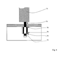
- FIG. 4 shows a detail of a door according to the invention.
- a door leaf 41 has one extending from its lower edge Open up.
- a roller bearing 45 Guide element 44 attached in the form of a guide roller, the is rotatable about a vertical axis, not shown.
- the Guide element 44 consists essentially of a Band guide section 44.1, a lower end plate 44.2 and an upper section 44.3 in the area of the roller bearings 45.
- a Volume 43 the bandwidth of which extends in the vertical direction extends, runs around the tape guide section 44.1 of the Guide element 44.
- the band guide section 41 forms between the end plate 44.2 and the upper section 44.3 a groove-like depression on the surface of the Guide element 44. This recess forms a Guiding structure for the tape, that for lateral guidance of the tape 43 in one circulation of the tape 43 around Guide element 44 provides.
- FIG. 5A and 5B show a further variant of the Door according to the invention, with a door leaf 61.
- Fig. 5A shows the door leaf 61 in a first position
- FIG. 5B in a second position, in which the door leaf 61 compared to the first Location is shifted by a distance A.
- the leadership tools comprise an open band 63 and two guide elements 64, 65 on the door leaf 61.
- the first guide element 64 is a Longitudinal guide for a first band end 63.1, which is in the Direction of displacement of the door leaf 61 extends.
- the second Guide element 65 is a deflection element or a Pulley.
- the band 63 is 63.2 with its second band end attached to or in the area of the frame, not shown.
- Spring elements can be used, the one Contact pressure of the belt in the direction of the guide surface ensure and / or the pre-tensioning of the tape produce.
- Nylon guide elements are particularly suitable or Teflon coated elements that allow the tape to slide enable.
- the tape can also be carried out in various forms and be redirected.
- the band laterally when the door leaf is moved lead there is the variant, a management structure for lateral guidance of the belt on the guide surface itself train.
- This variant is shown in Fig. 6.
- In 6 is a slidable along a guide surface 78 Door leaf 71 in a cross section perpendicular to Direction of displacement of the door leaf shown.
- On the door leaf a guide element 74 is fastened around which a band 73 which one lying flat on the guide surface 78 Hinge section includes when the door leaf is displaced is moved.
- the guide structure for the band 73 is in shape a groove 79 formed, the lateral Movement of the band 73 perpendicular to Direction of movement of the door leaf 71 on the guide surface 78 concentrated.
- a one-sided or double-sided lateral guide structure created for one of the tapes disclosed be that a guide element for the tape and / or the associated guide surface on one or both sides of the Be appropriately structured to the band Freedom of movement of the belt transverse to the direction of movement of the Restrict door leaf.
- the tape as a layer structure of several Layers with different material compositions train.
- one with the guide element layer to be brought into contact made of a material be that there is little sliding friction between the belt and Guiding element guaranteed.
- the material for another Layer can be chosen so that the tape is large Tear resistance, especially when loaded in the Direction of displacement of the door leaf.
- One with the The surface to be brought into contact with the guide surface could be made a dirt-insensitive and / or wear-resistant material or so be optimized that an optimal seal on the Guide surface is reached.
- a good seal ensures, for example, a slat structure Slats along the direction of displacement of the door leaf are oriented, especially if the lamellar structure is made of an elastic material is formed and thus the The prerequisite is that the slats under the Effect of a low contact pressure a gapless Make contact with the guide surface.
- the guide element 44 which is perpendicular about an axis is rotatable to the direction of movement of the door leaf - or general guide elements that occur when the Door leaf together with that on the guide element Band section are movable, it can be an advantage be when the side of the belt lying against the guide element is made of a material that has a high static friction guaranteed with respect to the surface of the guide element. So when the door leaf is moved, the transport of the Band around the guide element easily controllable.
- the invention offers the possibility of the nature of the Interfaces between the guide element and the adjacent one Optimally match each other regardless of the band Condition of the management area.
- the invention is also applicable to straight or curved door leaves that run lengthways be guided on a curved guide surface.
Landscapes
- Engineering & Computer Science (AREA)
- Mechanical Engineering (AREA)
- Elevator Door Apparatuses (AREA)
Abstract
Description
Die Erfindung ist im Folgenden anhand in den Zeichnungen dargestellter Ausführungsbeispiele ausführlich beschrieben.
- Fig. 1A
- eine Türe nach der Erfindung, von vorne;
- Fig. 1B
- die in Fig. 1 dargestellte Türe, ausschnittsweise, in vergrössertem Massstab;
- Fig. 1C
- die in den Fig. 1A und 1B dargestellte Türe, in einem seitlichen Schnitt;
- Fig. 2A
- ein Türblatt mit Führungsmitteln für eine Türe nach der Erfindung, wobei das Türblatt eine erste Lage einnimmt, von oben,
- Fig. 2B
- das in Fig. 2A dargestellte Türblatt mit Führungsmitteln, wobei das Türblatt eine zweite Lage einnimmt, in gleicher Darstellung wie Fig. 2A;
- Fig. 3A
- ein Türblatt mit Führungsmitteln für eine Türe nach der Erfindung, sowie weitere Führungsmittel, die ebenfalls Führungselemente und ein Band umfassen, wobei das Türblatt eine erste Lage einnimmt, in gleicher Darstellung wie die Fig. 2A und 2B;
- Fig. 3B
- die in Fig. 3A dargestellte Türblatt mit Führungsmitteln, wobei das Türblatt eine zweite Lage einnimmt, in gleicher Darstellung wie die Fig. 2A, 2B und 3A;
- Fig. 4
- ein Türblatt, mit Führungsmitteln, ausschnittsweise, in einem vertikalen Schnitt;
- Fig. 5A
- noch ein weiteres Türblatt mit Führungsmitteln, wobei das Türblatt eine erste Lage einnimmt, in gleicher Darstellung wie die Fig. 2A, 2B, 3A und 3B;
- Fig. 5B
- das in Fig. 5A dargestellte Türblatt mit Führungsmitteln, wobei das Türblatt eine zweite Lage einnimmt, in gleicher Darstellung wie die Fig. 2A, 2B, 3A und 3B; und
- Fig. 6
- ein weiteres Türblatt, mit Führungsmitteln, ausschnittsweise, in einem vertikalen Schnitt.
Claims (11)
- Türe (10) mit einem in einer Verschiebungsrichtung (12; 22; 32) entlang einer Führungsfläche (18; 28; 38.1, 38.2) der Tür (10) verschiebbaren Türblatt (11; 21; 31; 41; 61), mit mindestens einem Element zwischen dem Türblatt (11; 21; 31; 41; 61) und der Führungsfläche (18; 28; 38.1, 38.2), welches Element ein Führungsteil (14, 15; 24, 25; 34.1, 34.2, 35.1, 35.2; 44.1, 44.2, 44.3; 64, 65) zum Führen eines Abschnitts eines beweglichen Bandes (13; 23; 33.1, 33.2; 43; 63) aufweist, welcher Abschnitt während einer Verschiebung des Türblatts (11; 21; 31; 41; 61) mit der Führungsfläche (18; 28; 38.1, 38.2) in Kontakt steht, dadurch gekennzeichnet, dass das Führungsteil (14, 15; 24, 25; 34.1, 34.2, 35.1, 35.2; 44.1, 44.2, 44.3; 64, 65) in seiner länglichen Ausdehnung im wesentlichen parallel zu einer Ebene des Türblatts (11; 21; 31; 41; 61) und parallel zur Führungsfläche (18; 28; 38.1, 38.2) angeordnet ist.
- Türe (10) nach Anspruch 1, dadurch gekennzeichnet, dass die Führungsfläche (18; 28; 38.1, 38.2;) sich im Bereich eines Türrahmens (19) oder einer Türzarge befindet.
- Türe nach Anspruche 1, dadurch gekennzeichnet, dass die Elemente im Bereich eines Türrahmens oder einer Türzarge angeordnet sind und sich die Führungsfläche im Bereich der Kante des Türblattes befindet.
- Türe (10) nach einem der vorhergehenden Ansprüche, dadurch gekennzeichnet, dass das Band (13; 23; 33; 43;63) elastische Eigenschaften aufweist.
- Türe (10) nach einem der vorangehenden Ansprüche,
dadurch gekennzeichnet, dass sie eine weitere Führungsfläche (38.1), ein weiteres Band (33.2) und weitere Führungsteile (34.2, 35.2) aufweist. - Türe nach einem der vorangehenden Ansprüche, dadurch gekennzeichnet, dass mindestens ein Führungsteil (14, 15; 24, 25; 34.1, 35.1, 34.2, 35.2; 44.1, 44.2, 44.3; 65) als Rolle ausgebildet und drehbar befestigt ist.
- Türe nach einem der vorangehenden Ansprüche, dadurch gekennzeichnet, dass das Band (13; 23; 33.1, 33.2; 43; 63) auf die Führungsfläche hin zustellbar ist.
- Türe nach einem der vorangehenden Ansprüche, dadurch gekennzeichnet, dass das Band (13; 23; 33.1, 33.2; 43; 63) neben einer Führungsfunktion auch eine Dichtfunktion ausübt.
- Türe nach einem der vorangehenden Ansprüche, dadurch gekennzeichnet, dass das Band (43, 73) seitlich geführt ist mittels einer Führungsstruktur (44.2, 44.3,79), welche an mindestens einem der Führungsteile (44) und/oder der Führungsfläche (78) ausgebildet ist.
- Türe nach einem der vorangehenden Ansprüche, dadurch gekennzeichnet, dass das Band eine Schichtstruktur aufweist.
- Aufzugsanlage mit einer Türe gemäss einem der Ansprüche 1 bis 10, wobei die Türe eine Schachttüre oder eine Kabinentüre ist.
Priority Applications (1)
| Application Number | Priority Date | Filing Date | Title |
|---|---|---|---|
| EP03021881A EP1405976A1 (de) | 2002-10-04 | 2003-09-27 | Türe mit verschiebbarem Türblatt und mit Führungsmitteln |
Applications Claiming Priority (3)
| Application Number | Priority Date | Filing Date | Title |
|---|---|---|---|
| EP02022422 | 2002-10-04 | ||
| EP02022422 | 2002-10-04 | ||
| EP03021881A EP1405976A1 (de) | 2002-10-04 | 2003-09-27 | Türe mit verschiebbarem Türblatt und mit Führungsmitteln |
Publications (1)
| Publication Number | Publication Date |
|---|---|
| EP1405976A1 true EP1405976A1 (de) | 2004-04-07 |
Family
ID=31995526
Family Applications (1)
| Application Number | Title | Priority Date | Filing Date |
|---|---|---|---|
| EP03021881A Withdrawn EP1405976A1 (de) | 2002-10-04 | 2003-09-27 | Türe mit verschiebbarem Türblatt und mit Führungsmitteln |
Country Status (1)
| Country | Link |
|---|---|
| EP (1) | EP1405976A1 (de) |
Citations (4)
| Publication number | Priority date | Publication date | Assignee | Title |
|---|---|---|---|---|
| US2708285A (en) * | 1953-05-07 | 1955-05-17 | Greenspon Henry | Ball bearing mounting apparatus for sliding panel |
| US3255807A (en) * | 1964-06-22 | 1966-06-14 | Jr Harry F Steele | Self contained sliding door device |
| US4781270A (en) * | 1987-03-02 | 1988-11-01 | Delaware Capital Formation, Inc. | Elevator door arrangement |
| US5273363A (en) * | 1991-09-23 | 1993-12-28 | Ashland Products, Inc. | Roller for sliding windows and doors |
-
2003
- 2003-09-27 EP EP03021881A patent/EP1405976A1/de not_active Withdrawn
Patent Citations (4)
| Publication number | Priority date | Publication date | Assignee | Title |
|---|---|---|---|---|
| US2708285A (en) * | 1953-05-07 | 1955-05-17 | Greenspon Henry | Ball bearing mounting apparatus for sliding panel |
| US3255807A (en) * | 1964-06-22 | 1966-06-14 | Jr Harry F Steele | Self contained sliding door device |
| US4781270A (en) * | 1987-03-02 | 1988-11-01 | Delaware Capital Formation, Inc. | Elevator door arrangement |
| US5273363A (en) * | 1991-09-23 | 1993-12-28 | Ashland Products, Inc. | Roller for sliding windows and doors |
Similar Documents
| Publication | Publication Date | Title |
|---|---|---|
| DE2227931A1 (de) | Gleitvorrichtung | |
| DE102015120555B3 (de) | Band für Türen oder Fenster | |
| EP3380692B1 (de) | Schiebewandanordnung mit abdeckelement | |
| EP1762759B1 (de) | Ventilmechanik für ein Vakuumventil | |
| DE202009014785U1 (de) | Schiebetür | |
| DE3328888C1 (de) | Antrieb für das Öffnen und Schließen einer Tür oder eines Tores | |
| EP1890908A1 (de) | Handverstellung für eine lordosenstütze eines fahrzeugsitzes | |
| EP0905343B1 (de) | Fenster- oder Türanordung | |
| DE4105093A1 (de) | Fensterpositioniereinrichtung, insbesondere steuereinrichtung zum heben und senken eines kraftfahrzeugfensters | |
| EP1522666B1 (de) | Beschlag für Hebe-Schiebe-Türen oder -Fenster sowie Laufschuh für einen solchen Beschlag | |
| EP4457415A1 (de) | Barrierefreie schiebetür mit einem querabstellbaren flügel | |
| DE2702731A1 (de) | Tuerfeststeller fuer kraftwagentueren | |
| DE102018101247B4 (de) | Schiebetür | |
| DE19907767B4 (de) | Beschlag | |
| DE60307142T2 (de) | Zugluftausschließende Vorrichtung, insbesondere für Türen und ähnliches | |
| DE102019219974A1 (de) | Schiebeflügelanordnung mit beweglicher Führungsschiene | |
| DE19838205A1 (de) | Sektionaltor | |
| DE3741386A1 (de) | Federnde scharnieranordnung fuer schwenktueren, insbesondere fuer automobiltueren | |
| DE3210952A1 (de) | Schiebefenster | |
| AT523298B1 (de) | Jalousieschrank sowie Jalousie hierfür | |
| AT518630B1 (de) | Dichtungsvorrichtung | |
| DE19719011A1 (de) | Führungsschiene für ein Laufwerk mit am Laufwerk hängend gelagerten Trennwänden oder dergleichen | |
| AT405805B (de) | Schiebefenster | |
| EP3527740A1 (de) | Dachfenster | |
| DE20316484U1 (de) | Beschlag für Hebe-Schiebe-Türen oder -Fenster sowie Laufschuh für einen solchen Beschlag |
Legal Events
| Date | Code | Title | Description |
|---|---|---|---|
| PUAI | Public reference made under article 153(3) epc to a published international application that has entered the european phase |
Free format text: ORIGINAL CODE: 0009012 |
|
| AK | Designated contracting states |
Kind code of ref document: A1 Designated state(s): AT BE BG CH CY CZ DE DK EE ES FI FR GB GR HU IE IT LI LU MC NL PT RO SE SI SK TR |
|
| AX | Request for extension of the european patent |
Extension state: AL LT LV MK |
|
| 17P | Request for examination filed |
Effective date: 20040927 |
|
| AKX | Designation fees paid |
Designated state(s): AT CH DE FR GB LI |
|
| REG | Reference to a national code |
Ref country code: HK Ref legal event code: DE Ref document number: 1065086 Country of ref document: HK |
|
| 17Q | First examination report despatched |
Effective date: 20090331 |
|
| STAA | Information on the status of an ep patent application or granted ep patent |
Free format text: STATUS: THE APPLICATION IS DEEMED TO BE WITHDRAWN |
|
| 18D | Application deemed to be withdrawn |
Effective date: 20090811 |
|
| REG | Reference to a national code |
Ref country code: HK Ref legal event code: WD Ref document number: 1065086 Country of ref document: HK |