EP1405810A1 - Drahtspule und Restdrahterkennungsverfahren - Google Patents
Drahtspule und Restdrahterkennungsverfahren Download PDFInfo
- Publication number
- EP1405810A1 EP1405810A1 EP03020468A EP03020468A EP1405810A1 EP 1405810 A1 EP1405810 A1 EP 1405810A1 EP 03020468 A EP03020468 A EP 03020468A EP 03020468 A EP03020468 A EP 03020468A EP 1405810 A1 EP1405810 A1 EP 1405810A1
- Authority
- EP
- European Patent Office
- Prior art keywords
- wire
- coil
- magnet
- turns
- spool according
- Prior art date
- Legal status (The legal status is an assumption and is not a legal conclusion. Google has not performed a legal analysis and makes no representation as to the accuracy of the status listed.)
- Granted
Links
Images



Classifications
-
- B—PERFORMING OPERATIONS; TRANSPORTING
- B65—CONVEYING; PACKING; STORING; HANDLING THIN OR FILAMENTARY MATERIAL
- B65H—HANDLING THIN OR FILAMENTARY MATERIAL, e.g. SHEETS, WEBS, CABLES
- B65H63/00—Warning or safety devices, e.g. automatic fault detectors, stop-motions ; Quality control of the package
- B65H63/08—Warning or safety devices, e.g. automatic fault detectors, stop-motions ; Quality control of the package responsive to delivery of a measured length of material, completion of winding of a package, or filling of a receptacle
- B65H63/086—Warning or safety devices, e.g. automatic fault detectors, stop-motions ; Quality control of the package responsive to delivery of a measured length of material, completion of winding of a package, or filling of a receptacle responsive to completion of unwinding of a package
-
- G—PHYSICS
- G01—MEASURING; TESTING
- G01V—GEOPHYSICS; GRAVITATIONAL MEASUREMENTS; DETECTING MASSES OR OBJECTS; TAGS
- G01V3/00—Electric or magnetic prospecting or detecting; Measuring magnetic field characteristics of the earth, e.g. declination, deviation
- G01V3/08—Electric or magnetic prospecting or detecting; Measuring magnetic field characteristics of the earth, e.g. declination, deviation operating with magnetic or electric fields produced or modified by objects or geological structures or by detecting devices
-
- B—PERFORMING OPERATIONS; TRANSPORTING
- B65—CONVEYING; PACKING; STORING; HANDLING THIN OR FILAMENTARY MATERIAL
- B65H—HANDLING THIN OR FILAMENTARY MATERIAL, e.g. SHEETS, WEBS, CABLES
- B65H2553/00—Sensing or detecting means
- B65H2553/20—Sensing or detecting means using electric elements
- B65H2553/22—Magnetic detectors, e.g. Hall detectors
-
- Y—GENERAL TAGGING OF NEW TECHNOLOGICAL DEVELOPMENTS; GENERAL TAGGING OF CROSS-SECTIONAL TECHNOLOGIES SPANNING OVER SEVERAL SECTIONS OF THE IPC; TECHNICAL SUBJECTS COVERED BY FORMER USPC CROSS-REFERENCE ART COLLECTIONS [XRACs] AND DIGESTS
- Y10—TECHNICAL SUBJECTS COVERED BY FORMER USPC
- Y10S—TECHNICAL SUBJECTS COVERED BY FORMER USPC CROSS-REFERENCE ART COLLECTIONS [XRACs] AND DIGESTS
- Y10S242/00—Winding, tensioning, or guiding
- Y10S242/912—Indicator or alarm
Definitions
- the invention relates to a device for storing wire, in particular one Wire spool according to the preamble of claim 1, and a method for Residual wire detection with such a wire coil.
- Devices of the type mentioned are typically used to wire a to provide wire processing machine, for example a device, the wire comb binding elements for binding stacks of sheet-shaped substrates manufactures.
- the operator can also find the wire coil by looking at it no accurate indication of how many meters of wire remained on the wire spool and for how many welds, workpieces or semi-finished products the wire is still sufficient. It is therefore desirable to have the remaining amount of wire on the wire spool to know, or at least at a certain point in time, especially if only now There is little wire available to be informed of how many meters of wire are left of the wire coil are available.
- Methods and devices for residual wire detection are known from the prior art known in various ways. Use some of these devices or methods electrically resistive methods in which current through the wire by means of a contact is conducted and based on the measurable resistance of the wire to the length of the Wire can be closed. However, these procedures are not applicable to plastic-coated wire, as it is often used for wire comb binding elements becomes. Other methods use optical means to keep the remaining amount of wire to determine. Such processes are typically prone to contamination, in addition, these processes sometimes require complex and therefore expensive optics. Such Methods or devices are particularly necessary when filament is on the Wire coil to be detected that has no magnetic or electrical properties has, e.g. Yarn.
- magnetic mechanisms are used, e.g. B. to signal how much metal cable is left on a spool.
- patent specification CA 1 270 502 uses a magnet in the coil body introduced, which is in an operative relationship with a magnetic sensor that is outside the Coil wall is attached and the magnet once with each rotation of the coil faces.
- the magnetization of the magnet is such that the magnetic Field lines are led through the cable turns above the magnet stand on the cable drum perpendicular to the winding direction of the cable.
- the continuous conduction of the magnetic field lines, i.e. the magnetic flux through The adjacent cable turns works especially well when the cable is not covered.
- the one Permeability is less than that of the cable. Now there is no cable above the magnet, so the magnetic field lines through it Intermediate element directed near the magnetic sensor so that it generates a signal. This signal correlates with the absence of the cable and can therefore be used as an indication be evaluated that only a predetermined number of turns on the Wire spool are left.
- JP 60015360 a device for Residual wire quantity detection for welding wire disclosed, which is also a magnetic Principle used.
- the contact arm remains an insulating element in contact with the wire, through the permanent magnet existing wire causes a signal in the magnetic sensor as soon as there is no more wire is present, the magnetic sensor switches off, so that a signal is generated that conveys that there is little wire left on the wire spool.
- a method for detecting residual wire on a wire coil would be desirable, especially for the detection of the remaining wire length of coated wire, the is inexpensive, a very precise indication of the remaining meters of wire allows one Can prevent damage to the wire processing device, as well as a wire coil, with which such a method can be carried out.
- a wire coil for residual wire detection is for wire with a wire start and a wire end wound on a bobbin in N windings provided, the coil former side walls and a coil drum comprises and has a magnet which is fixed in the coil body, the Installation eye of the magnet in the coil body is such that the magnetic Field lines along the magnet substantially parallel to the winding direction of the Wire are arranged on the wire spool.
- the magnet is advantageously a bar magnet, which is its has magnetic poles at the ends of the rod, and in particular a cylindrical Has shape.
- a cylindrical bar magnet with such magnetization generates in Compared to rectangular bar magnets, a more homogeneous magnetic field in the circumferential direction.
- the diameter of the bar magnet is advantageously chosen such that it is the three- is up to ten times the wire diameter. For example, one Wire diameter of 1 mm a cylindrical bar magnet with a diameter of 5 mm recommended.
- the magnetization of the bar magnet is essentially parallel to the Direction of winding of the wire turns, a single wire winding covers one considerable area of the bar magnet to the outside.
- a magnetic sensor is arranged so that the wire turns between the magnetic sensor and the bar magnet come to rest, so there is a single wire winding correspondingly a significant proportion of the magnetic field emanating from the bar magnet shielded.
- the wire coil is rotated and the wire tangential deducted. In this case, the magnet and the magnetic sensor meet once per Revolution.
- the magnetic sensor for example a reed relay, is used with the Accuracy of one to two turns of wire on the wire spool can respond. at a diameter of the wire coil of approx. 30 cm corresponds to an accuracy of 1 up to 2 meters of wire.
- the magnet a distance to a coil wall so that a certain number of Wire windings n remain on the spool drum as soon as all windings over the Magnets were unwound.
- This number n of remaining turns corresponds to multiplied by the circumference of the wire spool just the remaining wire length on the Wire coil.
- This information is with the error of one or two mentioned above Wire windings are affected, but this error is absolute and relativized increasing number n of the remaining wire turns.
- Controlling one wire processing device can provide this information about the remaining wire length use to estimate how many more workpieces or semi-finished products are made can and can be the operator of the wire processing device thereon Clues.
- the number n of remaining wire turns can be applied to the wire processing device, but will always be at least as large that the job where the wire processing device has the most wire used, can still be processed in any case.
- the first turns on the coil drum close together and / or are from one Adhesive element fixed loosely.
- Adhesive element fixed loosely.
- This can ensure that the assumed number of turns of wire between the magnet and the end of the wire is available.
- the use of a double-sided adhesive tape improves and makes the winding even easier.
- the double-sided adhesive guarantees Adhesive tape that when unwinding the last turns actually turn to turn remain and the shielding of the magnet by the wire is not lost prematurely.
- loose fixation means that the wire turns adhere to the double-sided adhesive tape, but with effort, with where the wire is pulled from the wire spool, detached effortlessly and without deformation can be.
- alternatives are also available Fastening methods from the prior art applicable, the corresponding Allow loosely fixing the wire windings.
- the device also has an insertable magnet holder, by means of which the magnet in the wire spool is positioned.
- the Magnetic holder snap hooks that bite the bobbin.
- the magnet cannot move away from its intended rotation of the wire spool Move position in relation to the coil wall or simply drop out again. This can in particular ensure that the number n remaining Wire windings between bar magnet and coil wall actually the intended one Number n of remaining wire turns corresponds.
- the Wire coil holders for a straight wire end and / or a straight wire start on In the state of the art it has so far mostly only been possible to do this on the coil former the bent wire end to bend it over so before winding the wire spool on Fix the bobbin. Likewise, a spool that is partially unwound is usually used has been exchanged and stored, the open wire start is bent over to prevent the wire windings from being at least partially damaged by their internal stress unwinding by itself.
- One reason for such an exchange of coils is Example of changing the wire color or other wire parameters without the Wire spool would already be completely used up, for example due to a job change.
- the wire processing device is in generally do not accept a bent or bent wire start, so that the user must use a tool to help the bent wire start remove, for example a pair of wire cutters. With a holder for the wire start on the This does not require a coil where the start of the wire is not bent. A straight one The end of the wire has the simple advantage that the end of the wire is not additionally bent must become.
- the Wire spool has a bracket for a straight wire end, with the bracket on Has locking element that prevents the wire end from being pulled out of the holder.
- This can be achieved in a simple manner that after simply inserting the Wired this hooked and the following turns taut and swirl can be wound on a turn.
- the opening for Inserting the wire end an insertion bevel, on the one hand to insert make it easier to find a wire end that is as bend as possible.
- Locking element a predetermined breaking point so that with a certain pull that is applied when the wire is pulled off the wire spool, and that pulls to the ideal Winding exceeds, the locking element is destroyed and the wire end released becomes. In this way, the wire can be completely unwound from the wire spool. It also prevents the wire processing device from accidentally removing the Wire coil tears out of the holder or other damage can occur, for example in the wire feeder.
- the material of the holder is advantageously around spring steel.
- the Wire coil brackets for a straight wire start the brackets on Extent exist several times. In this way it can be guaranteed that always just a short straight piece of wire from the nearest bracket for the beginning of the wire protrudes. On the one hand, this has the advantage that the risk of injury is reduced, on the other hand the likelihood is improved that the straight start of the wire when Using the wire spool back into the wire processing device easily can be threaded and has not been damaged during storage, e.g. is bent.
- the holder is pronounced on the edge of the coil, tapered, conical clamping guides, between which the wire start over a longer one Stretch is clamped.
- the Clamping guides formed undercuts behind which the wire is clamped has to snap. This gives the user tactile feedback as to whether he is using the Wire jam is also securely clamped.
- the jamming of the The beginning of the wire can be further improved by such a measure.
- you can alternatively, a large number of other mounting mechanisms can also be used are known to the person skilled in the art on the basis of his specialist knowledge.
- the Wire spool in a device for producing wire comb binding elements used the wire comb binding elements in particular flexible with different parameters such as loop length and number of loops can be manufactured. It is particularly useful here to know whether the next thing to be manufactured Wire binding element is still sufficient wire, or not, because the Wire binding elements in their size and thus in the required wire considerably can distinguish.
- inventive concept encompasses a method for the detection of residual wire Wire on a bobbin, with the steps: providing an inventive Wire coil, providing a magnetic sensor in an operative relationship with the magnet in the bobbin; Detecting an electrical signal from the magnetic sensor in response the absence of wire between the magnetic sensor and the magnet; and Signal the remaining wire turns on the wire spool to a higher-level one electronics
- the magnetic sensor is in particular a reed relay, alternatively can a Hall probe or a comparable mechanism can also be used.
- a suitable control system can be used Determine the total length of the remaining wire as soon as it receives the signal from the Magnetic sensor has received and can use this information to an operator to tell how many workpieces or semi-finished products he made from the remaining wire on the wire spool can still manufacture.
- it is a remaining wire length that in is still sufficient to close the workpiece or semi-finished product finish and favorably one or two more workpieces or semi-finished products finished.
- the higher-level controller advantageously signals the user of the wire processing device the approaching wire end, acoustically, on a User interface, optically or by other mechanisms known to the person skilled in the art.
- FIGs 1a and 1b the principle of shielding the magnetic field lines 11, 12 of the Bar magnet 10 shown by the wire 1.
- the bar magnet 10 is a cylindrical permanent magnet, the magnetization being such that the magnetic poles are each at the ends of the bar magnet 10.
- the magnetic field initially extends radially in all directions, the magnetic field lines 11, 12 in Run essentially parallel to the orientation of the bar magnet 10. In that area, in which the magnetic field lines 12 reach the area of the ferromagnetic wire 1, the magnetic field lines 12 run within the wire 1, the magnetic field is on the other side of the wire turns of the wire 1 shielded.
- a reed relay attached there 20 therefore does not respond.
- a reed relay 20 is a Switch comprising two closely adjacent filaments 21, which are present when present of a magnetic field attract each other and thereby close a circuit.
- a Hall probe can also be used as a sensor for the magnetic field.
- the wire 1 is removed from the space between Reed relay 20 and bar magnet 10 removed, in particular from the coil drum 30 processed so far that the wire windings no longer or only the bar magnet 20 cover it partially, the shielding effect of wire 1 and the reed relay is no longer applicable 20 switches.
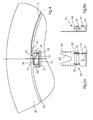
- FIGS. 2a and 2b show the relevant section of an embodiment of the Wire spool according to the invention shown.
- wire 1 is of course shown in complete turns wound around the coil drum 30.
- the bar magnet 10 is in a recess in the coil body 30, 40 attached so that its cylinder jacket as possible lies close to the surface of the coil drum 30 and the bar magnet 10 a determined distance D to one of the coil walls 40.
- the wire spool is in a device, so that the magnetic sensor provided in this device 20 has essentially the same distance D from the coil wall 40, wherein Bar magnet 10 and magnetic sensor are essentially parallel to each other, as well as in Substantially parallel to the wire turns and essentially parallel to the Magnetic field lines 11, 12 along the bar magnet 10.
- the wire end 2 can by different mechanisms on the coil drum 30 or the coil wall 40, e.g. under one from the coil wall 40 to the inside protruding lip (Figure 3a), or in a recess within the coil wall 40th ( Figure 3b). After attaching the wire end 2 to the wire spool in the the arrow 3 marked filling direction turn to turn of the wire 1 on the Adhesive tape 60 filed.
- FIG. 4 Another preferred fastening mechanism for the wire end 2 is shown in FIG. 4 shown.
- FIGS. 5a and 5b these are the Magnetic holder 50 which is inserted laterally into the coil body 30.
- the beginning of the wire 2 is here along an inlet flank 33 in the recess 34 in the area of Magnetic holder 50 inserted and by a resilient locking element 51 against the beveled, aligned with the inlet flank offset by a wire thickness 32 of the Recess 34 pressed.
- the locking element 51 is designed such that it is one Barb is right at the wire end 2, so that just inserted Wire end 2 cannot be removed from the recess 34 without being destroyed.
- the Locking element 51 is also in one embodiment with a predetermined breaking point provided, which leads to the destruction of the locking element 51 when the wire end with a certain force is pulled out of the holder.
- the bursting or breaking off of the Latching element 51 leads to a last acoustic signal that wire 1 is no longer on the Wire spool is in place, so the user of a wire processing device still once has the opportunity to interrupt the wire removal.
- the predetermined breaking point in the Locking element can also protect other machine parts, especially the suspension of the Wire spool and possibly its drive.
- the magnet holder 50 has on the support plate 53 made of spring steel, which in the Coil body 30 is inserted next to holding elements 52 which fix the magnet 10 Locking teeth 54, which are typically when inserted with the bobbin 30, 40 consists of a plastic, interlock and thus prevent the position of the Magnets 10 in the coil body 30, 40 changed, which otherwise leads to an inaccuracy would lead to the detection of residual wire.
- the support plate 53 is on her other end bent to an end plate 55, which the recess 34 to the outside closes.
- FIGS. 6a, 6b and 6c show details of the fastening of the wire start 4.
- the Coil wall 40 has several, on the side facing the user openings 43 evenly distributed over the circumference. Between the Breakthroughs are two conical clamping guides 41 that allow the Clamp wire start 4 in it. In the front area of the clamping guides 41 there is one Flat threading aid 42 is provided, on the sides of which the clamping guides converge. Undercuts, not shown, are between the clamping guides molded, behind which the wire must snap when clamped. The user receives this provides tactile feedback as to whether he has securely pinched the start of the wire. In this way, the beginning of the wire 4 can be kept taut and straight, so that at a wire coil change the user immediately a straight wire 4 to Is made available that it is easier to insert into his wire processing device can.
- the invention is also suitable with an electromagnet Power supply possible, but it is preferred to use a permanent magnet 10 use.
Landscapes
- Engineering & Computer Science (AREA)
- Remote Sensing (AREA)
- Physics & Mathematics (AREA)
- Life Sciences & Earth Sciences (AREA)
- General Life Sciences & Earth Sciences (AREA)
- Electromagnetism (AREA)
- Environmental & Geological Engineering (AREA)
- Geology (AREA)
- Quality & Reliability (AREA)
- General Physics & Mathematics (AREA)
- Geophysics (AREA)
- Filamentary Materials, Packages, And Safety Devices Therefor (AREA)
- Storage Of Web-Like Or Filamentary Materials (AREA)
- Length Measuring Devices With Unspecified Measuring Means (AREA)
- Metal Extraction Processes (AREA)
- Storing, Repeated Paying-Out, And Re-Storing Of Elongated Articles (AREA)
Abstract
Description
- Fig. 1a
- eine schematische Seitenansicht des magnetischen Feldes des Magneten bei Vorhandensein des Drahtes;
- Fig. 1b
- eine schematische Vorderansicht des magnetischen Feldes des Magneten bei Vorhandensein des Drahtes;
- Fig. 1c
- eine schematische Seitenansicht des magnetischen Feldes des Magneten bei Abwesenheit des Drahtes;
- Fig. 1d
- eine schematische Vorderansicht des magnetischen Feldes des Magneten bei Abwesenheit des Drahtes;
- Fig. 2 a
- eine schematische Darstellung der oberen Hälfte der erfindungsgemäßen Drahtspule in Draufsicht;
- Fig. 2b
- eine schematische Darstellung der oberen Hälfte der erfindungsgemäßen Drahtspule in Seitenansicht;
- Fig. 3a
- vergrößerte schematische Detailansicht des Bereichs um den Magneten in der erfindungsgemäßen Drahtspule in einer ersten Ausführungsform;
- Fig. 3b
- vergrößerte schematische Detailansicht des Bereichs um den Magneten in der erfindungsgemäßen Drahtspule in einer zweiten Ausführungsform;
- Fig. 4
- schematische Detailansicht des Bereichs um den Magneten in der erfindungsgemäßen Drahtspule mit Halterung für den Magneten und das Drahtende;
- Fig. 5a
- schematische Draufsicht der Halterung für den Magneten und das Drahtende;
- Fig. 5b
- schematische Seitenansicht der Halterung für den Magneten und das Drahtende;
- Fig. 6a
- schematische Draufsicht einer Drahtanfangsbefestigung in der Seitenwand der Spule;
- Fig. 6b
- schematische Seitenansicht in Drahtrichtung einer Drahtanfangsbefestigung in der Seitenwand der Spule;
- Fig. 6c
- vergrößerte schematische Seitenansicht in Drahtrichtung einer Drahtanfangsbefestigung in der Seitenwand der Spule.
- 1
- Draht
- 2
- Drahtende
- 3
- Befüllrichtung
- 4
- Drahtanfang
- 10
- Magnet
- 11
- magnetische Feldlinie
- 12
- abgeschirmte magnetische Feldlinie
- 20
- Magnetsensor
- 21
- Filament
- 30
- Spulentrommel
- 31
- Boden der Aussparung
- 32
- abgeschrägte Decke der Aussparung
- 33
- Einlaufflanke
- 34
- Aussparung
- 36
- Seitenwand der Aussparung
- 40
- Spulenwand
- 41
- Klemmführung
- 42
- Einfädelhilfe
- 43
- Durchbruch
- 50
- Magnethalterung
- 51
- Rastelement
- 52
- Halteelement
- 53
- Trägerplatte
- 54
- Rasthaken
- 55
- Abschlussplatte
- 60
- Klebeband
Claims (10)
- Drahtspule für Restdrahterkennung für Draht (1) mit einem Drahtanfang (4) und einem Drahtende (2), der auf einem Spulenkörper (30, 40) in N Windungen aufgewickelt ist, wobei der Spulenkörper (30, 40) beidseitig Seitenwände (40) und eine Spulentrommel (30) umfasst, mit einem Magneten (10), der in dem Spulenkörper (30, 40) befestigt ist,
dadurch gekennzeichnet, dass die Einbaulauge des Magneten (10) in dem Spulenkörper (30, 40) derart ist, dass die magnetischen Feldlinien (11, 12) entlang des Magneten (10) im Wesentlichen parallel zu der Wickelrichtung des Drahtes (1) auf der Spulentrommel (30) angeordnet sind. - Drahtspule nach Anspruch 1,
dadurch gekennzeichnet, dass der Magnet (10) eine Entfernung zu einer Spulenwand (40) aufweist, so dass eine bestimmte Anzahl von Drahtwicklungen n auf der Spulentrommel (30) verbleiben, sobald alle Wicklungen über dem Magneten (10) abgewickelt wurden. - Drahtspule nach einem der Ansprüche 1 bis 2,
dadurch gekennzeichnet, dass die ersten n Windungen auf der Spulentrommel (30) dicht nebeneinander liegen und / oder die ersten n Windungen von einem Klebeelement (60) lose fixiert sind. - Drahtspule nach einem der Ansprüche 1 bis 3,
dadurch gekennzeichnet, dass die Vorrichtung zudem eine einsteckbare Magnethalterung (50) umfasst, vermittels der der Magnet 10 in der Drahtspule positioniert wird - Drahtspule nach Anspruch 4,
dadurch gekennzeichnet, dass die Magnethalterung (50) Rasthaken (54) aufweist, die sich mit dem Spulenkörper (30, 40) verbeißen. - Drahtspule nach einem der Ansprüche 1 bis 5,
dadurch gekennzeichnet, dass die Drahtspule Halterungen (41, 50, 51, 53) für ein gerades Drahtende (2) und oder einen geraden Drahtanfang (4) aufweist - Drahtspule nach einem der Ansprüche 1 bis 6,
dadurch gekennzeichnet, dass die Drahtspule eine Halterung (50, 51, 53) für ein gerades Drahtende (2) aufweist, wobei die Halterung (50, 51, 53) ein Rastelement (51) aufweist, das das Herausziehen des Drahtendes (2) aus der Halterung (50, 51, 53) verhindert. - Drahtspule nach einem der Ansprüche 1 bis 7,
dadurch gekennzeichnet, dass die Drahtspule Halterungen (41) für einen geraden Drahtanfang (4) aufweist, wobei die Halterungen (41) am Umfang der Spulenwände (40) mehrfach vorhanden sind - Drahtspule nach einem der Ansprüche 1 bis 8,
dadurch gekennzeichnet, dass die Drahtspule in einer Vorrichtung zur Herstellung von Drahtkammbindeelementen, wobei die Drahtkammbindeelemente insbesondere flexibel mit unterschiedlichen Parametern wie Schlaufenlänge und Schlaufenanzahl gefertigt werden. - Verfahren zur Restdrahterkennung von Draht (1) auf einer Spulentrommel (30), mit den folgenden Schritten:Bereitstellen einer Drahtspule nach einem der Ansprüche 1 bis 9;Bereitstellen eines Magnetsensors (20) in einer Wirkbeziehung mit dem Magneten (10) im Spulenkörper (30, 40)Detektieren eines elektrischen Signals vom Magnetsensor (20) in Ansprechen auf die Abwesenheit von Draht (1) zwischen dem Magnetsensor (20) und dem Magneten (10); undSignalisieren der verbleibenden Drahtwindungen auf der Drahtspule an eine übergeordnete Elektronik
Applications Claiming Priority (2)
| Application Number | Priority Date | Filing Date | Title |
|---|---|---|---|
| DE10246075 | 2002-10-02 | ||
| DE10246075A DE10246075A1 (de) | 2002-10-02 | 2002-10-02 | Drahtspule und Restdrahterkennungsverfahren |
Publications (2)
| Publication Number | Publication Date |
|---|---|
| EP1405810A1 true EP1405810A1 (de) | 2004-04-07 |
| EP1405810B1 EP1405810B1 (de) | 2006-05-24 |
Family
ID=31984363
Family Applications (1)
| Application Number | Title | Priority Date | Filing Date |
|---|---|---|---|
| EP03020468A Expired - Lifetime EP1405810B1 (de) | 2002-10-02 | 2003-09-15 | Drahtspule und Restdrahterkennungsverfahren |
Country Status (6)
| Country | Link |
|---|---|
| US (1) | US6921044B2 (de) |
| EP (1) | EP1405810B1 (de) |
| JP (1) | JP2004123389A (de) |
| CN (1) | CN100343148C (de) |
| AT (1) | ATE327204T1 (de) |
| DE (2) | DE10246075A1 (de) |
Cited By (3)
| Publication number | Priority date | Publication date | Assignee | Title |
|---|---|---|---|---|
| WO2010012015A1 (de) * | 2008-07-31 | 2010-02-04 | Andritz Ag | Vorrichtung zum entsorgen von restdraht |
| EP3461772A1 (de) * | 2017-09-29 | 2019-04-03 | Partzsch Spezialdrähte e.K. | Verfahren und vorrichtung zur optimalen nutzung des wicklungsgutes bei der auf- und/oder abwicklung |
| WO2019063031A1 (de) * | 2017-09-29 | 2019-04-04 | PARTZSCH Spezialdrähte e.K. | Verfahren und vorrichtung zur optimalen nutzung des wicklungsgutes bei der auf- und/oder abwicklung |
Families Citing this family (6)
| Publication number | Priority date | Publication date | Assignee | Title |
|---|---|---|---|---|
| DE102005003293A1 (de) * | 2005-01-24 | 2006-07-27 | Continental Teves Ag & Co. Ohg | Befestigungsvorrichtung für Sensoren oder Aktoren |
| AT502849B1 (de) * | 2005-11-30 | 2010-09-15 | Lunatone Ind Elektronik Gmbh | Spulgut-menge und -reserve detektor |
| US9809416B1 (en) | 2012-12-15 | 2017-11-07 | Southwire Company, Llc | Cable reel length calculator |
| KR101906816B1 (ko) * | 2017-02-17 | 2018-10-12 | 한국생산기술연구원 | 모니터링 장치 및 이의 방법 |
| CN109533435A (zh) * | 2018-12-28 | 2019-03-29 | 广东顺德华焱电子科技有限公司 | 绕丝盘绕丝余量检测装置及方法、钢筋捆扎机及工作方法 |
| CN117968510B (zh) * | 2024-04-01 | 2024-06-07 | 中铁电气化局集团有限公司 | 一种基于电阻值检测的用于检测接触网附加线余量的设备 |
Citations (2)
| Publication number | Priority date | Publication date | Assignee | Title |
|---|---|---|---|---|
| US4676442A (en) * | 1984-08-16 | 1987-06-30 | Aktiebolaget Iro | Yarn accumulation and feeding apparatus |
| CA1270502A (en) * | 1987-09-28 | 1990-06-19 | Richard J. Religa | Steel cable activated magnetic switch |
Family Cites Families (7)
| Publication number | Priority date | Publication date | Assignee | Title |
|---|---|---|---|---|
| JPS6015360A (ja) * | 1983-07-07 | 1985-01-26 | Mitsubishi Electric Corp | ワイヤ残量検出装置 |
| DE4021744A1 (de) * | 1990-07-07 | 1992-01-09 | Tsk Testsysteme Gmbh & Co | Spule zum aufwickeln von kabeln |
| DE9115063U1 (de) * | 1991-12-04 | 1993-04-01 | Westfalia Kunststoffe GmbH, 4950 Minden | Spule aus Kunststoff |
| DE4308288C1 (de) * | 1993-03-16 | 1994-09-29 | Signode Bernpak Gmbh | Wickelkern für Umreifungsmittel zum Umreifen von Packstücken |
| EP0648701A1 (de) * | 1993-10-19 | 1995-04-19 | Teijin Seiki Company Limited | Vorrichtung zum Aufspulen von Garnen |
| DE9401503U1 (de) * | 1994-01-29 | 1994-04-28 | Stewing Kunststoffbetrieb GmbH, 46282 Dorsten | Kabeltrommel |
| JP2806899B2 (ja) * | 1995-11-17 | 1998-09-30 | 日特エンジニアリング株式会社 | 線条材の巻取装置 |
-
2002
- 2002-10-02 DE DE10246075A patent/DE10246075A1/de not_active Withdrawn
-
2003
- 2003-09-15 EP EP03020468A patent/EP1405810B1/de not_active Expired - Lifetime
- 2003-09-15 DE DE50303450T patent/DE50303450D1/de not_active Expired - Lifetime
- 2003-09-15 AT AT03020468T patent/ATE327204T1/de not_active IP Right Cessation
- 2003-09-29 US US10/673,304 patent/US6921044B2/en not_active Expired - Fee Related
- 2003-09-30 CN CNB031326846A patent/CN100343148C/zh not_active Expired - Fee Related
- 2003-10-02 JP JP2003343898A patent/JP2004123389A/ja active Pending
Patent Citations (2)
| Publication number | Priority date | Publication date | Assignee | Title |
|---|---|---|---|---|
| US4676442A (en) * | 1984-08-16 | 1987-06-30 | Aktiebolaget Iro | Yarn accumulation and feeding apparatus |
| CA1270502A (en) * | 1987-09-28 | 1990-06-19 | Richard J. Religa | Steel cable activated magnetic switch |
Cited By (4)
| Publication number | Priority date | Publication date | Assignee | Title |
|---|---|---|---|---|
| WO2010012015A1 (de) * | 2008-07-31 | 2010-02-04 | Andritz Ag | Vorrichtung zum entsorgen von restdraht |
| EP3461772A1 (de) * | 2017-09-29 | 2019-04-03 | Partzsch Spezialdrähte e.K. | Verfahren und vorrichtung zur optimalen nutzung des wicklungsgutes bei der auf- und/oder abwicklung |
| WO2019063031A1 (de) * | 2017-09-29 | 2019-04-04 | PARTZSCH Spezialdrähte e.K. | Verfahren und vorrichtung zur optimalen nutzung des wicklungsgutes bei der auf- und/oder abwicklung |
| US11292689B2 (en) | 2017-09-29 | 2022-04-05 | PARTZSCH Spezialdrähte e.K. | Method and device for the optimal use of windable material during winding up and/or unwinding |
Also Published As
| Publication number | Publication date |
|---|---|
| ATE327204T1 (de) | 2006-06-15 |
| HK1066203A1 (zh) | 2005-03-18 |
| EP1405810B1 (de) | 2006-05-24 |
| CN100343148C (zh) | 2007-10-17 |
| JP2004123389A (ja) | 2004-04-22 |
| US20040113009A1 (en) | 2004-06-17 |
| US6921044B2 (en) | 2005-07-26 |
| DE50303450D1 (de) | 2006-06-29 |
| DE10246075A1 (de) | 2004-04-22 |
| CN1496946A (zh) | 2004-05-19 |
Similar Documents
| Publication | Publication Date | Title |
|---|---|---|
| DE2539873B2 (de) | Sicherheitseinrichtung an einem bandfoerderer | |
| DE4334811A1 (de) | Positionserfassungsvorrichtung an einem Linearantrieb | |
| EP1405810B1 (de) | Drahtspule und Restdrahterkennungsverfahren | |
| EP1543486A1 (de) | Globus | |
| DE102009022333A1 (de) | Magnetbohrständer mit Überwachung der Haltekraft | |
| DE102013113115B4 (de) | Verfahren zur Steuerung der Fadenlieferung, Fadenliefergerät und System mit Fadenliefergeräten | |
| DE19539936B4 (de) | Spulenfadenwickelvorrichtung zur Verwendung in einer Nähmaschine | |
| EP2589695B1 (de) | Verfahren zum automatischen Aufspulen einer Spule und einer Garnrolle sowie Spuleinrichtung zur Durchführung des Verfahrens | |
| DE2543986A1 (de) | Verfahren und vorrichtung zur sicherung einer reservewicklung auf einer spulenhuelse | |
| DE69904991T2 (de) | Fadenstoppvorrichtung für Schussfadenmess- und liefervorrichtungen für Luftdüsenwebmaschinen | |
| DE4141207A1 (de) | Vorrichtung zum ermitteln einer restmenge eines um einen spulenkern aufgewickelten spulenfadens | |
| EP3241794A1 (de) | Verfahren zum handhaben eines fadenendes und spulstelle | |
| DE69900832T2 (de) | Modulierte Schussfadenbremse für Textilmaschinen | |
| DE102014118743B4 (de) | Verfahren zur Steuerung der Fadenlieferung eines Fadenliefergerät und Fadenliefergerät | |
| DE2928916C3 (de) | Einrichtung zum Befestigen des Magnetbandes an den Spulen in einer Magnetbandkassette | |
| EP2036847A2 (de) | Verfahren und Vorrichtung zum Positionieren eines Fingerfadenführers einer Kreuzspulen herstellenden Textilmaschine | |
| DE3119000C2 (de) | ||
| DE102014206251B3 (de) | Wickelvorrichtung und Verfahren zu deren Betrieb | |
| DE112009001415T5 (de) | Vorrichtung und Verfahren zum Aufwickeln von Kabel- oder Drahtstücken zu einer Spule (Coll) mit zwei weiterbearbeitbaren Enden | |
| DE4142078C2 (de) | Fadenwächter für die Überwachung der Fadenspannung an Textilmaschinen | |
| DE3702049C2 (de) | ||
| EP2176156A1 (de) | Vorrichtung zum schneiden eines fadenförmigen körpers | |
| EP3159442B1 (de) | Verfahren zur steuerung der fadenlieferung eines fadenliefergeräts und fadenliefergerät | |
| WO2004013028A1 (de) | Vorrichtung zum fangen eines fadens am anfang einer spulreise | |
| DE19708139A1 (de) | Fadenliefervorrichtung, insbesondere für Strick- und Wirkmaschinen |
Legal Events
| Date | Code | Title | Description |
|---|---|---|---|
| PUAI | Public reference made under article 153(3) epc to a published international application that has entered the european phase |
Free format text: ORIGINAL CODE: 0009012 |
|
| AK | Designated contracting states |
Kind code of ref document: A1 Designated state(s): AT BE BG CH CY CZ DE DK EE ES FI FR GB GR HU IE IT LI LU MC NL PT RO SE SI SK TR |
|
| AX | Request for extension of the european patent |
Extension state: AL LT LV MK |
|
| 17P | Request for examination filed |
Effective date: 20041007 |
|
| AKX | Designation fees paid |
Designated state(s): AT BE BG CH CY CZ DE DK EE ES FI FR GB GR HU IE IT LI LU MC NL PT RO SE SI SK TR |
|
| 17Q | First examination report despatched |
Effective date: 20050506 |
|
| GRAP | Despatch of communication of intention to grant a patent |
Free format text: ORIGINAL CODE: EPIDOSNIGR1 |
|
| GRAS | Grant fee paid |
Free format text: ORIGINAL CODE: EPIDOSNIGR3 |
|
| GRAA | (expected) grant |
Free format text: ORIGINAL CODE: 0009210 |
|
| AK | Designated contracting states |
Kind code of ref document: B1 Designated state(s): AT BE BG CH CY CZ DE DK EE ES FI FR GB GR HU IE IT LI LU MC NL PT RO SE SI SK TR |
|
| PG25 | Lapsed in a contracting state [announced via postgrant information from national office to epo] |
Ref country code: RO Free format text: LAPSE BECAUSE OF FAILURE TO SUBMIT A TRANSLATION OF THE DESCRIPTION OR TO PAY THE FEE WITHIN THE PRESCRIBED TIME-LIMIT Effective date: 20060524 Ref country code: GB Free format text: LAPSE BECAUSE OF FAILURE TO SUBMIT A TRANSLATION OF THE DESCRIPTION OR TO PAY THE FEE WITHIN THE PRESCRIBED TIME-LIMIT Effective date: 20060524 Ref country code: IE Free format text: LAPSE BECAUSE OF FAILURE TO SUBMIT A TRANSLATION OF THE DESCRIPTION OR TO PAY THE FEE WITHIN THE PRESCRIBED TIME-LIMIT Effective date: 20060524 Ref country code: CZ Free format text: LAPSE BECAUSE OF FAILURE TO SUBMIT A TRANSLATION OF THE DESCRIPTION OR TO PAY THE FEE WITHIN THE PRESCRIBED TIME-LIMIT Effective date: 20060524 Ref country code: SI Free format text: LAPSE BECAUSE OF FAILURE TO SUBMIT A TRANSLATION OF THE DESCRIPTION OR TO PAY THE FEE WITHIN THE PRESCRIBED TIME-LIMIT Effective date: 20060524 Ref country code: FI Free format text: LAPSE BECAUSE OF FAILURE TO SUBMIT A TRANSLATION OF THE DESCRIPTION OR TO PAY THE FEE WITHIN THE PRESCRIBED TIME-LIMIT Effective date: 20060524 Ref country code: SK Free format text: LAPSE BECAUSE OF FAILURE TO SUBMIT A TRANSLATION OF THE DESCRIPTION OR TO PAY THE FEE WITHIN THE PRESCRIBED TIME-LIMIT Effective date: 20060524 |
|
| REG | Reference to a national code |
Ref country code: GB Ref legal event code: FG4D Free format text: NOT ENGLISH |
|
| REG | Reference to a national code |
Ref country code: CH Ref legal event code: EP |
|
| REG | Reference to a national code |
Ref country code: IE Ref legal event code: FG4D Free format text: LANGUAGE OF EP DOCUMENT: GERMAN |
|
| REF | Corresponds to: |
Ref document number: 50303450 Country of ref document: DE Date of ref document: 20060629 Kind code of ref document: P |
|
| PG25 | Lapsed in a contracting state [announced via postgrant information from national office to epo] |
Ref country code: DK Free format text: LAPSE BECAUSE OF FAILURE TO SUBMIT A TRANSLATION OF THE DESCRIPTION OR TO PAY THE FEE WITHIN THE PRESCRIBED TIME-LIMIT Effective date: 20060824 Ref country code: SE Free format text: LAPSE BECAUSE OF FAILURE TO SUBMIT A TRANSLATION OF THE DESCRIPTION OR TO PAY THE FEE WITHIN THE PRESCRIBED TIME-LIMIT Effective date: 20060824 |
|
| PG25 | Lapsed in a contracting state [announced via postgrant information from national office to epo] |
Ref country code: ES Free format text: LAPSE BECAUSE OF FAILURE TO SUBMIT A TRANSLATION OF THE DESCRIPTION OR TO PAY THE FEE WITHIN THE PRESCRIBED TIME-LIMIT Effective date: 20060904 |
|
| PG25 | Lapsed in a contracting state [announced via postgrant information from national office to epo] |
Ref country code: MC Free format text: LAPSE BECAUSE OF NON-PAYMENT OF DUE FEES Effective date: 20060930 Ref country code: BE Free format text: LAPSE BECAUSE OF NON-PAYMENT OF DUE FEES Effective date: 20060930 |
|
| PG25 | Lapsed in a contracting state [announced via postgrant information from national office to epo] |
Ref country code: PT Free format text: LAPSE BECAUSE OF FAILURE TO SUBMIT A TRANSLATION OF THE DESCRIPTION OR TO PAY THE FEE WITHIN THE PRESCRIBED TIME-LIMIT Effective date: 20061024 |
|
| GBV | Gb: ep patent (uk) treated as always having been void in accordance with gb section 77(7)/1977 [no translation filed] |
Effective date: 20060524 |
|
| REG | Reference to a national code |
Ref country code: IE Ref legal event code: FD4D |
|
| PLBE | No opposition filed within time limit |
Free format text: ORIGINAL CODE: 0009261 |
|
| STAA | Information on the status of an ep patent application or granted ep patent |
Free format text: STATUS: NO OPPOSITION FILED WITHIN TIME LIMIT |
|
| 26N | No opposition filed |
Effective date: 20070227 |
|
| EN | Fr: translation not filed | ||
| PG25 | Lapsed in a contracting state [announced via postgrant information from national office to epo] |
Ref country code: AT Free format text: LAPSE BECAUSE OF NON-PAYMENT OF DUE FEES Effective date: 20060915 |
|
| BERE | Be: lapsed |
Owner name: HEIDELBERGER DRUCKMASCHINEN A.G. Effective date: 20060930 |
|
| PG25 | Lapsed in a contracting state [announced via postgrant information from national office to epo] |
Ref country code: GR Free format text: LAPSE BECAUSE OF FAILURE TO SUBMIT A TRANSLATION OF THE DESCRIPTION OR TO PAY THE FEE WITHIN THE PRESCRIBED TIME-LIMIT Effective date: 20060825 Ref country code: FR Free format text: LAPSE BECAUSE OF FAILURE TO SUBMIT A TRANSLATION OF THE DESCRIPTION OR TO PAY THE FEE WITHIN THE PRESCRIBED TIME-LIMIT Effective date: 20070309 |
|
| REG | Reference to a national code |
Ref country code: CH Ref legal event code: PL |
|
| PG25 | Lapsed in a contracting state [announced via postgrant information from national office to epo] |
Ref country code: EE Free format text: LAPSE BECAUSE OF FAILURE TO SUBMIT A TRANSLATION OF THE DESCRIPTION OR TO PAY THE FEE WITHIN THE PRESCRIBED TIME-LIMIT Effective date: 20060524 Ref country code: BG Free format text: LAPSE BECAUSE OF FAILURE TO SUBMIT A TRANSLATION OF THE DESCRIPTION OR TO PAY THE FEE WITHIN THE PRESCRIBED TIME-LIMIT Effective date: 20060824 |
|
| PG25 | Lapsed in a contracting state [announced via postgrant information from national office to epo] |
Ref country code: LI Free format text: LAPSE BECAUSE OF NON-PAYMENT OF DUE FEES Effective date: 20070930 Ref country code: HU Free format text: LAPSE BECAUSE OF FAILURE TO SUBMIT A TRANSLATION OF THE DESCRIPTION OR TO PAY THE FEE WITHIN THE PRESCRIBED TIME-LIMIT Effective date: 20061125 Ref country code: LU Free format text: LAPSE BECAUSE OF NON-PAYMENT OF DUE FEES Effective date: 20060915 Ref country code: TR Free format text: LAPSE BECAUSE OF FAILURE TO SUBMIT A TRANSLATION OF THE DESCRIPTION OR TO PAY THE FEE WITHIN THE PRESCRIBED TIME-LIMIT Effective date: 20060524 Ref country code: CH Free format text: LAPSE BECAUSE OF NON-PAYMENT OF DUE FEES Effective date: 20070930 |
|
| PG25 | Lapsed in a contracting state [announced via postgrant information from national office to epo] |
Ref country code: FR Free format text: LAPSE BECAUSE OF FAILURE TO SUBMIT A TRANSLATION OF THE DESCRIPTION OR TO PAY THE FEE WITHIN THE PRESCRIBED TIME-LIMIT Effective date: 20060524 Ref country code: CY Free format text: LAPSE BECAUSE OF FAILURE TO SUBMIT A TRANSLATION OF THE DESCRIPTION OR TO PAY THE FEE WITHIN THE PRESCRIBED TIME-LIMIT Effective date: 20060524 |
|
| PGFP | Annual fee paid to national office [announced via postgrant information from national office to epo] |
Ref country code: DE Payment date: 20160930 Year of fee payment: 14 Ref country code: NL Payment date: 20160919 Year of fee payment: 14 |
|
| PGFP | Annual fee paid to national office [announced via postgrant information from national office to epo] |
Ref country code: IT Payment date: 20160930 Year of fee payment: 14 |
|
| REG | Reference to a national code |
Ref country code: DE Ref legal event code: R119 Ref document number: 50303450 Country of ref document: DE |
|
| REG | Reference to a national code |
Ref country code: NL Ref legal event code: MM Effective date: 20171001 |
|
| PG25 | Lapsed in a contracting state [announced via postgrant information from national office to epo] |
Ref country code: NL Free format text: LAPSE BECAUSE OF NON-PAYMENT OF DUE FEES Effective date: 20171001 |
|
| PG25 | Lapsed in a contracting state [announced via postgrant information from national office to epo] |
Ref country code: DE Free format text: LAPSE BECAUSE OF NON-PAYMENT OF DUE FEES Effective date: 20180404 |
|
| PG25 | Lapsed in a contracting state [announced via postgrant information from national office to epo] |
Ref country code: IT Free format text: LAPSE BECAUSE OF NON-PAYMENT OF DUE FEES Effective date: 20170915 |