EP1405795A1 - Mehrwegverpackung für Pumpen - Google Patents
Mehrwegverpackung für Pumpen Download PDFInfo
- Publication number
- EP1405795A1 EP1405795A1 EP03020679A EP03020679A EP1405795A1 EP 1405795 A1 EP1405795 A1 EP 1405795A1 EP 03020679 A EP03020679 A EP 03020679A EP 03020679 A EP03020679 A EP 03020679A EP 1405795 A1 EP1405795 A1 EP 1405795A1
- Authority
- EP
- European Patent Office
- Prior art keywords
- strips
- bolts
- pump
- flange
- pumps
- Prior art date
- Legal status (The legal status is an assumption and is not a legal conclusion. Google has not performed a legal analysis and makes no representation as to the accuracy of the status listed.)
- Granted
Links
- 238000004806 packaging method and process Methods 0.000 claims description 6
- 238000012856 packing Methods 0.000 abstract description 2
- 238000003780 insertion Methods 0.000 description 2
- 230000037431 insertion Effects 0.000 description 2
- 239000000463 material Substances 0.000 description 2
- 208000012886 Vertigo Diseases 0.000 description 1
- 238000010276 construction Methods 0.000 description 1
- 238000006073 displacement reaction Methods 0.000 description 1
- 239000005022 packaging material Substances 0.000 description 1
- 239000002023 wood Substances 0.000 description 1
Images

Classifications
-
- B—PERFORMING OPERATIONS; TRANSPORTING
- B65—CONVEYING; PACKING; STORING; HANDLING THIN OR FILAMENTARY MATERIAL
- B65D—CONTAINERS FOR STORAGE OR TRANSPORT OF ARTICLES OR MATERIALS, e.g. BAGS, BARRELS, BOTTLES, BOXES, CANS, CARTONS, CRATES, DRUMS, JARS, TANKS, HOPPERS, FORWARDING CONTAINERS; ACCESSORIES, CLOSURES, OR FITTINGS THEREFOR; PACKAGING ELEMENTS; PACKAGES
- B65D19/00—Pallets or like platforms, with or without side walls, for supporting loads to be lifted or lowered
- B65D19/0002—Platforms, i.e. load supporting devices without provision for handling by a forklift
-
- B—PERFORMING OPERATIONS; TRANSPORTING
- B65—CONVEYING; PACKING; STORING; HANDLING THIN OR FILAMENTARY MATERIAL
- B65D—CONTAINERS FOR STORAGE OR TRANSPORT OF ARTICLES OR MATERIALS, e.g. BAGS, BARRELS, BOTTLES, BOXES, CANS, CARTONS, CRATES, DRUMS, JARS, TANKS, HOPPERS, FORWARDING CONTAINERS; ACCESSORIES, CLOSURES, OR FITTINGS THEREFOR; PACKAGING ELEMENTS; PACKAGES
- B65D19/00—Pallets or like platforms, with or without side walls, for supporting loads to be lifted or lowered
- B65D19/38—Details or accessories
- B65D19/44—Elements or devices for locating articles on platforms
-
- B—PERFORMING OPERATIONS; TRANSPORTING
- B65—CONVEYING; PACKING; STORING; HANDLING THIN OR FILAMENTARY MATERIAL
- B65D—CONTAINERS FOR STORAGE OR TRANSPORT OF ARTICLES OR MATERIALS, e.g. BAGS, BARRELS, BOTTLES, BOXES, CANS, CARTONS, CRATES, DRUMS, JARS, TANKS, HOPPERS, FORWARDING CONTAINERS; ACCESSORIES, CLOSURES, OR FITTINGS THEREFOR; PACKAGING ELEMENTS; PACKAGES
- B65D2519/00—Pallets or like platforms, with or without side walls, for supporting loads to be lifted or lowered
- B65D2519/00004—Details relating to pallets
- B65D2519/00258—Overall construction
- B65D2519/00263—Overall construction of the pallet
- B65D2519/00273—Overall construction of the pallet made of more than one piece
-
- B—PERFORMING OPERATIONS; TRANSPORTING
- B65—CONVEYING; PACKING; STORING; HANDLING THIN OR FILAMENTARY MATERIAL
- B65D—CONTAINERS FOR STORAGE OR TRANSPORT OF ARTICLES OR MATERIALS, e.g. BAGS, BARRELS, BOTTLES, BOXES, CANS, CARTONS, CRATES, DRUMS, JARS, TANKS, HOPPERS, FORWARDING CONTAINERS; ACCESSORIES, CLOSURES, OR FITTINGS THEREFOR; PACKAGING ELEMENTS; PACKAGES
- B65D2519/00—Pallets or like platforms, with or without side walls, for supporting loads to be lifted or lowered
- B65D2519/00004—Details relating to pallets
- B65D2519/00258—Overall construction
- B65D2519/00283—Overall construction of the load supporting surface
- B65D2519/00293—Overall construction of the load supporting surface made of more than one piece
-
- B—PERFORMING OPERATIONS; TRANSPORTING
- B65—CONVEYING; PACKING; STORING; HANDLING THIN OR FILAMENTARY MATERIAL
- B65D—CONTAINERS FOR STORAGE OR TRANSPORT OF ARTICLES OR MATERIALS, e.g. BAGS, BARRELS, BOTTLES, BOXES, CANS, CARTONS, CRATES, DRUMS, JARS, TANKS, HOPPERS, FORWARDING CONTAINERS; ACCESSORIES, CLOSURES, OR FITTINGS THEREFOR; PACKAGING ELEMENTS; PACKAGES
- B65D2519/00—Pallets or like platforms, with or without side walls, for supporting loads to be lifted or lowered
- B65D2519/00004—Details relating to pallets
- B65D2519/00258—Overall construction
- B65D2519/00313—Overall construction of the base surface
- B65D2519/00318—Overall construction of the base surface made of one piece
-
- B—PERFORMING OPERATIONS; TRANSPORTING
- B65—CONVEYING; PACKING; STORING; HANDLING THIN OR FILAMENTARY MATERIAL
- B65D—CONTAINERS FOR STORAGE OR TRANSPORT OF ARTICLES OR MATERIALS, e.g. BAGS, BARRELS, BOTTLES, BOXES, CANS, CARTONS, CRATES, DRUMS, JARS, TANKS, HOPPERS, FORWARDING CONTAINERS; ACCESSORIES, CLOSURES, OR FITTINGS THEREFOR; PACKAGING ELEMENTS; PACKAGES
- B65D2519/00—Pallets or like platforms, with or without side walls, for supporting loads to be lifted or lowered
- B65D2519/00004—Details relating to pallets
- B65D2519/00258—Overall construction
- B65D2519/00313—Overall construction of the base surface
- B65D2519/00328—Overall construction of the base surface shape of the contact surface of the base
- B65D2519/00343—Overall construction of the base surface shape of the contact surface of the base contact surface being substantially in the form of a panel
-
- B—PERFORMING OPERATIONS; TRANSPORTING
- B65—CONVEYING; PACKING; STORING; HANDLING THIN OR FILAMENTARY MATERIAL
- B65D—CONTAINERS FOR STORAGE OR TRANSPORT OF ARTICLES OR MATERIALS, e.g. BAGS, BARRELS, BOTTLES, BOXES, CANS, CARTONS, CRATES, DRUMS, JARS, TANKS, HOPPERS, FORWARDING CONTAINERS; ACCESSORIES, CLOSURES, OR FITTINGS THEREFOR; PACKAGING ELEMENTS; PACKAGES
- B65D2519/00—Pallets or like platforms, with or without side walls, for supporting loads to be lifted or lowered
- B65D2519/00004—Details relating to pallets
- B65D2519/00258—Overall construction
- B65D2519/00398—Overall construction reinforcements
- B65D2519/00432—Non-integral, e.g. inserts
- B65D2519/00437—Non-integral, e.g. inserts on the load supporting surface
-
- B—PERFORMING OPERATIONS; TRANSPORTING
- B65—CONVEYING; PACKING; STORING; HANDLING THIN OR FILAMENTARY MATERIAL
- B65D—CONTAINERS FOR STORAGE OR TRANSPORT OF ARTICLES OR MATERIALS, e.g. BAGS, BARRELS, BOTTLES, BOXES, CANS, CARTONS, CRATES, DRUMS, JARS, TANKS, HOPPERS, FORWARDING CONTAINERS; ACCESSORIES, CLOSURES, OR FITTINGS THEREFOR; PACKAGING ELEMENTS; PACKAGES
- B65D2519/00—Pallets or like platforms, with or without side walls, for supporting loads to be lifted or lowered
- B65D2519/00004—Details relating to pallets
- B65D2519/00547—Connections
- B65D2519/00552—Structures connecting the constitutive elements of the pallet to each other, i.e. load supporting surface, base surface and/or separate spacer
- B65D2519/00572—Structures connecting the constitutive elements of the pallet to each other, i.e. load supporting surface, base surface and/or separate spacer with separate auxiliary element, e.g. screws, nails, bayonets
-
- B—PERFORMING OPERATIONS; TRANSPORTING
- B65—CONVEYING; PACKING; STORING; HANDLING THIN OR FILAMENTARY MATERIAL
- B65D—CONTAINERS FOR STORAGE OR TRANSPORT OF ARTICLES OR MATERIALS, e.g. BAGS, BARRELS, BOTTLES, BOXES, CANS, CARTONS, CRATES, DRUMS, JARS, TANKS, HOPPERS, FORWARDING CONTAINERS; ACCESSORIES, CLOSURES, OR FITTINGS THEREFOR; PACKAGING ELEMENTS; PACKAGES
- B65D2519/00—Pallets or like platforms, with or without side walls, for supporting loads to be lifted or lowered
- B65D2519/00004—Details relating to pallets
- B65D2519/00736—Details
- B65D2519/0081—Elements or devices for locating articles
- B65D2519/00815—Elements or devices for locating articles on the pallet
-
- B—PERFORMING OPERATIONS; TRANSPORTING
- B65—CONVEYING; PACKING; STORING; HANDLING THIN OR FILAMENTARY MATERIAL
- B65D—CONTAINERS FOR STORAGE OR TRANSPORT OF ARTICLES OR MATERIALS, e.g. BAGS, BARRELS, BOTTLES, BOXES, CANS, CARTONS, CRATES, DRUMS, JARS, TANKS, HOPPERS, FORWARDING CONTAINERS; ACCESSORIES, CLOSURES, OR FITTINGS THEREFOR; PACKAGING ELEMENTS; PACKAGES
- B65D2585/00—Containers, packaging elements or packages specially adapted for particular articles or materials
- B65D2585/68—Containers, packaging elements or packages specially adapted for particular articles or materials for machines, engines, or vehicles in assembled or dismantled form
- B65D2585/6802—Containers, packaging elements or packages specially adapted for particular articles or materials for machines, engines, or vehicles in assembled or dismantled form specific machines, engines or vehicles
- B65D2585/6875—Containers, packaging elements or packages specially adapted for particular articles or materials for machines, engines, or vehicles in assembled or dismantled form specific machines, engines or vehicles engines, motors, machines and vehicle parts
- B65D2585/6877—Containers, packaging elements or packages specially adapted for particular articles or materials for machines, engines, or vehicles in assembled or dismantled form specific machines, engines or vehicles engines, motors, machines and vehicle parts engines or motors
-
- Y—GENERAL TAGGING OF NEW TECHNOLOGICAL DEVELOPMENTS; GENERAL TAGGING OF CROSS-SECTIONAL TECHNOLOGIES SPANNING OVER SEVERAL SECTIONS OF THE IPC; TECHNICAL SUBJECTS COVERED BY FORMER USPC CROSS-REFERENCE ART COLLECTIONS [XRACs] AND DIGESTS
- Y02—TECHNOLOGIES OR APPLICATIONS FOR MITIGATION OR ADAPTATION AGAINST CLIMATE CHANGE
- Y02W—CLIMATE CHANGE MITIGATION TECHNOLOGIES RELATED TO WASTEWATER TREATMENT OR WASTE MANAGEMENT
- Y02W30/00—Technologies for solid waste management
- Y02W30/50—Reuse, recycling or recovery technologies
- Y02W30/80—Packaging reuse or recycling, e.g. of multilayer packaging
Definitions
- the invention relates to a device for packaging and transporting inline pumps, whose motor and pump shaft is vertical.
- the object of the invention is to provide reusable packaging for inline pumps create a secure fixation of the pump during transport, easy alignment and mounting of the pump enables mounting in the packaging and detaching from the packaging without tools and ensures a space-saving return transport.
- This object is achieved in that on a horizontal base plate at least two horizontal strips to each other are attached in parallel, their distance from each other the distance between the two outer pump flange surfaces corresponds to each other, and that on the mutually facing inner sides of the strips protrusions in pairs are arranged, two of which are each accessible from above Form a space into which the pump flange can be inserted.
- Such packaging enables easy attachment and removal of the Pumps, which are securely fixed during transport. Neither for that Setting up the pumps on the plate are still tools for removal required.
- the pumps can be lifted in with a crane. At the The device is particularly space-saving because it can be transported back without a pump has only a small height.
- a particularly simple construction is given when the protrusions vertical strips are on the inside of the horizontal strips are attached.
- a secure hold and easy handling is achieved when on the ledge bolts are slidably mounted in the bores of the pump flanges can be inserted.
- the bolts can be horizontal Bores of the strips can be axially locked axially in the flange bore.
- a secure hold is given when the bolts are inserted in the Flange bore can be locked axially. It is also proposed that axial bolt lock the bolts have a radial projection that after rotation of the bolt about its longitudinal axis in a recess especially the pocket of the lasts.
- the Bore of the bar in which the bolt is located has an extension that is closed by a plate with an opening and radial slot.
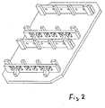
- the strips 2 On a horizontal base plate 1, four strips 2 are parallel to each other and each fixed at a distance such that the side surfaces 3 of the strips 2 stand vertically. In the attached position, the strips have one rectangular cross section with greater height H than width B.
- Two strips 2 each form a pair of strips with a constant distance A. from each other, so at this distance inline pumps in such a way are adjustable that the pump and motor axis are vertical and the two Flanges of the pump nozzle on the inner surfaces 4 of the strips 2 or are close.
- each bar 2 forms two horizontal ones Holes 7, which are arranged so that they match the holes in the Align the pump flange.
- Bolts 8 are or are in these bores retrofitted, inserting them into the holes in the pump flanges reach in so that the flanges and thus the pumps are securely attached to the strips 2 and thus attached to the device.
- Each bolt 8 has one Insertion area 9 and at the opposite end a bent part as a handle 10.
- a radial projection 11 is attached to the bolt 8, which in a Recess 12 or in a pocket on the bar 2 after the Bolt 8 was inserted and rotated about its longitudinal axis.
- the Recess or pocket 12 can, as shown in Fig. 1, from an outside be screwed to the bar 2 profile 13 formed.
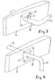
- FIGS. 2 to 4 shows the recess or Pocket formed by the bar 2, the recess or pocket of one externally attached or screwed plate 14 is covered, the one has radial slot 15 through which the projection 11 into the recess can be pushed. Then the bolt is turned so that the Projection 11 behind the plate 14 finds a hold and thus the bolt 8 safely is held against axial displacement.
- inline pumps or two double pumps or one double pump and two inline pumps attached become.
- the material of the base plate 1 and the strips 2, 5 is made preferably made of wood and / or plastic.
Landscapes
- Engineering & Computer Science (AREA)
- Mechanical Engineering (AREA)
- Structures Of Non-Positive Displacement Pumps (AREA)
- Details Of Reciprocating Pumps (AREA)
Abstract
Description
- Fig. 1
- eine isometrische Ansicht der Vorrichtung in einer ersten Ausführung,
- Fig. 2
- eine isometrische Ansicht der Vorrichtung in einer zweiten Ausführung,
- Fig. 3
- einen Ausschnitt aus der Vorrichtung nach Fig. 2 mit einer alternativen Arretierung des Bolzens während des Einsteckens des Bolzens,
- Fig. 4
- die Ausführung nach Fig. 3 nach dem Drehen des Bolzens in die arretierte Stellung.
Claims (9)
- Vorrichtung zum Verpacken und Transport von Inline-Pumpen, deren Motoren- und Pumpenwelle senkrecht steht, dadurch gekennzeichnet, dass auf einer waagerechten Grundplatte (1) mindestens zwei waagerechte Leisten (2) zueinander parallel befestigt sind, deren Abstand (A) voneinander dem Abstand der beiden äußeren Pumpen-Flanschflächen voneinander entspricht, und dass auf dem einander zugewandten Innenseiten der Leisten (2) paarweise Vorsprünge (5) angeordnet sind, von denen jeweils zwei einen von oben zugänglichen Zwischenraum (6) bilden, in den der Pumpen-Flansch einschiebbar ist.
- Vorrichtung nach Anspruch 1,dadurch gekennzeichnet, dass die Vorsprünge (5) senkrechte Leisten sind, die auf der Innenseite der waagerechten Leisten (2) befestigt sind.
- Vorrichtung nach Anspruch 1 oder 2, dadurch gekennzeichnet, dass an den Leisten (2) Bolzen (8) verschieblich befestigt sind, die in Bohrungen der Pumpen-Flansche einschiebbar sind.
- Vorrichtung nach Anspruch 3, dadurch gekennzeichnet, dass die Bolzen () in waagerechten Bohrungen (7) der Leisten (2) und in Flanschbohrungen axial einliegen.
- Vorrichtung nach Anspruch 3 oder 4, dadurch gekennzeichnet, dass die Bolzen (8) bei Einlage in der Flanschbohrung axial arretierbar sind.
- Vorrichtung nach Anspruch 4 oder 5, dadurch gekennzeichnet, dass zur axialen Bolzen-Arretierung die Bolzen (8) einen radialen Vorsprung (11) aufweisen, der nach Drehung des Bolzens um seine Längsachse in einer Ausnehmung insbesondere Tasche (12) der Leiste (2) einliegt.
- Vorrichtung nach Anspruch 6, dadurch gekennzeichnet, dass zur Bildung der Ausnehmung die Bohrung (7) der Leiste (2), in der der Bolzen (8) einliegt, eine Erweiterung aufweist, die durch eine Platte (14) mit Öffnung und radialem Schlitz (15) verschlossen ist.
- Vorrichtung nach einem der Ansprüche 3 bis 9, dadurch gekennzeichnet, dass die Bolzen (8) in axialer Richtung zum Pumpen-Flansch hin federbelastet sind.
- Vorrichtung nach einem der vorherigen Ansprüche, dadurch gekennzeichnet, dass auf der Grundplatte (1) Einzel- und Doppelpumpen befestigbar sind.
Applications Claiming Priority (2)
| Application Number | Priority Date | Filing Date | Title |
|---|---|---|---|
| DE10245829 | 2002-10-01 | ||
| DE2002145829 DE10245829A1 (de) | 2002-10-01 | 2002-10-01 | Mehrwegverpackung für Pumpen |
Publications (2)
| Publication Number | Publication Date |
|---|---|
| EP1405795A1 true EP1405795A1 (de) | 2004-04-07 |
| EP1405795B1 EP1405795B1 (de) | 2007-11-28 |
Family
ID=31984327
Family Applications (1)
| Application Number | Title | Priority Date | Filing Date |
|---|---|---|---|
| EP20030020679 Expired - Lifetime EP1405795B1 (de) | 2002-10-01 | 2003-09-11 | Mehrwegverpackung für Pumpen |
Country Status (2)
| Country | Link |
|---|---|
| EP (1) | EP1405795B1 (de) |
| DE (2) | DE10245829A1 (de) |
Cited By (3)
| Publication number | Priority date | Publication date | Assignee | Title |
|---|---|---|---|---|
| CN104058174A (zh) * | 2014-06-27 | 2014-09-24 | 浙江清钰科技有限公司 | 油泵保护珍珠棉装置 |
| AT523726B1 (de) * | 2020-08-03 | 2021-11-15 | Avl List Gmbh | RAHMENANORDNUNG FÜR EINEN GROßMOTOR |
| CN114074789A (zh) * | 2020-08-10 | 2022-02-22 | 中包物联网科技(天津)有限公司 | 一种通用型发动机智能循环器具及管理系统 |
Citations (5)
| Publication number | Priority date | Publication date | Assignee | Title |
|---|---|---|---|---|
| US3315800A (en) * | 1964-12-14 | 1967-04-25 | Hampton R Wagner | Collapsible plywood shipping device |
| DE7436916U (de) * | 1974-11-05 | 1975-06-12 | Werz Furnier Sperrholz | Verpackungseinheit fuer eine groessere Anzahl gestapelter sperrriger Gegenstaende |
| DE8023331U1 (de) * | 1980-09-02 | 1981-01-22 | Ruhrkohle Ag | Transportpalette |
| US4747495A (en) * | 1987-01-20 | 1988-05-31 | Chrysler Motors Corporation | Engine storage and transportation rack |
| US5154286A (en) * | 1991-04-23 | 1992-10-13 | Gits Jules C | Reusable shipping frame and adaptor saddles |
Family Cites Families (1)
| Publication number | Priority date | Publication date | Assignee | Title |
|---|---|---|---|---|
| DE20001697U1 (de) * | 2000-02-01 | 2000-03-30 | IMF Innovative Mechanik und Fertigungs GmbH, 38122 Braunschweig | Transportbehälter |
-
2002
- 2002-10-01 DE DE2002145829 patent/DE10245829A1/de not_active Withdrawn
-
2003
- 2003-09-11 DE DE50308676T patent/DE50308676D1/de not_active Expired - Fee Related
- 2003-09-11 EP EP20030020679 patent/EP1405795B1/de not_active Expired - Lifetime
Patent Citations (5)
| Publication number | Priority date | Publication date | Assignee | Title |
|---|---|---|---|---|
| US3315800A (en) * | 1964-12-14 | 1967-04-25 | Hampton R Wagner | Collapsible plywood shipping device |
| DE7436916U (de) * | 1974-11-05 | 1975-06-12 | Werz Furnier Sperrholz | Verpackungseinheit fuer eine groessere Anzahl gestapelter sperrriger Gegenstaende |
| DE8023331U1 (de) * | 1980-09-02 | 1981-01-22 | Ruhrkohle Ag | Transportpalette |
| US4747495A (en) * | 1987-01-20 | 1988-05-31 | Chrysler Motors Corporation | Engine storage and transportation rack |
| US5154286A (en) * | 1991-04-23 | 1992-10-13 | Gits Jules C | Reusable shipping frame and adaptor saddles |
Cited By (5)
| Publication number | Priority date | Publication date | Assignee | Title |
|---|---|---|---|---|
| CN104058174A (zh) * | 2014-06-27 | 2014-09-24 | 浙江清钰科技有限公司 | 油泵保护珍珠棉装置 |
| AT523726B1 (de) * | 2020-08-03 | 2021-11-15 | Avl List Gmbh | RAHMENANORDNUNG FÜR EINEN GROßMOTOR |
| AT523726A4 (de) * | 2020-08-03 | 2021-11-15 | Avl List Gmbh | RAHMENANORDNUNG FÜR EINEN GROßMOTOR |
| CN114074789A (zh) * | 2020-08-10 | 2022-02-22 | 中包物联网科技(天津)有限公司 | 一种通用型发动机智能循环器具及管理系统 |
| CN114074789B (zh) * | 2020-08-10 | 2025-01-28 | 中包物联网科技(天津)有限公司 | 一种通用型发动机智能循环器具及管理系统 |
Also Published As
| Publication number | Publication date |
|---|---|
| DE10245829A1 (de) | 2004-06-09 |
| DE50308676D1 (de) | 2008-01-10 |
| EP1405795B1 (de) | 2007-11-28 |
Similar Documents
| Publication | Publication Date | Title |
|---|---|---|
| DE3513384A1 (de) | Profilsystem zum bau von montageeinrichtungen, stuetzkonstruktionen und transportbaendern | |
| DE202006007821U1 (de) | Spann- oder Führungsschiene mit Verliersicherung für Haltebolzen | |
| DE69205957T2 (de) | Schienenführung für Förderer. | |
| EP0976891A2 (de) | Tragprofil für ein Aufbausystem | |
| EP1405795B1 (de) | Mehrwegverpackung für Pumpen | |
| AT408121B (de) | Scharnier für ein flügelteil, insbesondere einen tür- oder fensterflügel | |
| CH624174A5 (en) | Adjustable suspension for doors. | |
| DE7921206U1 (de) | Fertigwand aus vorgefertigten moduleinheiten | |
| DE2232790A1 (de) | Befestigungsanordnung fuer einen zylinder mit kolben | |
| DE4116080C2 (de) | Lösbare Schnappverbindungsvorrichtung für zwei Bauelemente | |
| DE3540848A1 (de) | Einsteckschloss mit variablem dornmass | |
| DE102021116812A1 (de) | Erweiterungsbausatz | |
| DE3220710C2 (de) | Webschaft | |
| DE1202682B (de) | Eckumlenkvorrichtung fuer die Treibstangen von Beschlaegen an Fenstern, Tueren od. dgl. | |
| DE2552983A1 (de) | Spannvorrichtung zum verbinden von geraetegehaeusen o.dgl. | |
| DE10129162A1 (de) | Schloß für Ganzglastüren | |
| DE8421156U1 (de) | Zerlegbarer Behaelter | |
| EP0135805A2 (de) | Türschloss | |
| DE1913729A1 (de) | Anpassbares Gestell | |
| DE2315982A1 (de) | Befestigungsvorrichtung fuer motoren, getriebegehaeuse, variatoren oder dgl., insbesondere fuer einen elektromotor, der bei einem maschinenwerkzeug oder dgl. eine riemenscheibe treibt | |
| DE8908272U1 (de) | Tragsäule für eine Bearbeitungsstation | |
| DE20011411U1 (de) | Verbindungselement zur Verbindung von Platten | |
| WO2024240815A1 (de) | Werkstückträgerrahmen und werkstückträgerrahmensystem | |
| DE2950571A1 (de) | Aufhaengevorrichtung fuer tueren oder tore | |
| DE202023104005U1 (de) | Trägervorrichtung für eine Gabelzinke |
Legal Events
| Date | Code | Title | Description |
|---|---|---|---|
| PUAI | Public reference made under article 153(3) epc to a published international application that has entered the european phase |
Free format text: ORIGINAL CODE: 0009012 |
|
| AK | Designated contracting states |
Kind code of ref document: A1 Designated state(s): AT BE BG CH CY CZ DE DK EE ES FI FR GB GR HU IE IT LI LU MC NL PT RO SE SI SK TR |
|
| AX | Request for extension of the european patent |
Extension state: AL LT LV MK |
|
| 17P | Request for examination filed |
Effective date: 20040316 |
|
| AKX | Designation fees paid |
Designated state(s): DE FR GB IT |
|
| 17Q | First examination report despatched |
Effective date: 20070103 |
|
| GRAP | Despatch of communication of intention to grant a patent |
Free format text: ORIGINAL CODE: EPIDOSNIGR1 |
|
| GRAS | Grant fee paid |
Free format text: ORIGINAL CODE: EPIDOSNIGR3 |
|
| GRAA | (expected) grant |
Free format text: ORIGINAL CODE: 0009210 |
|
| AK | Designated contracting states |
Kind code of ref document: B1 Designated state(s): DE FR GB IT |
|
| REG | Reference to a national code |
Ref country code: GB Ref legal event code: FG4D Free format text: NOT ENGLISH |
|
| GBT | Gb: translation of ep patent filed (gb section 77(6)(a)/1977) | ||
| REF | Corresponds to: |
Ref document number: 50308676 Country of ref document: DE Date of ref document: 20080110 Kind code of ref document: P |
|
| ET | Fr: translation filed | ||
| PLBE | No opposition filed within time limit |
Free format text: ORIGINAL CODE: 0009261 |
|
| STAA | Information on the status of an ep patent application or granted ep patent |
Free format text: STATUS: NO OPPOSITION FILED WITHIN TIME LIMIT |
|
| 26N | No opposition filed |
Effective date: 20080829 |
|
| PGFP | Annual fee paid to national office [announced via postgrant information from national office to epo] |
Ref country code: FR Payment date: 20080915 Year of fee payment: 6 |
|
| PGFP | Annual fee paid to national office [announced via postgrant information from national office to epo] |
Ref country code: GB Payment date: 20080917 Year of fee payment: 6 |
|
| PGFP | Annual fee paid to national office [announced via postgrant information from national office to epo] |
Ref country code: DE Payment date: 20080926 Year of fee payment: 6 |
|
| PGFP | Annual fee paid to national office [announced via postgrant information from national office to epo] |
Ref country code: IT Payment date: 20080927 Year of fee payment: 6 |
|
| GBPC | Gb: european patent ceased through non-payment of renewal fee |
Effective date: 20090911 |
|
| REG | Reference to a national code |
Ref country code: FR Ref legal event code: ST Effective date: 20100531 |
|
| PG25 | Lapsed in a contracting state [announced via postgrant information from national office to epo] |
Ref country code: FR Free format text: LAPSE BECAUSE OF NON-PAYMENT OF DUE FEES Effective date: 20090930 Ref country code: DE Free format text: LAPSE BECAUSE OF NON-PAYMENT OF DUE FEES Effective date: 20100401 |
|
| PG25 | Lapsed in a contracting state [announced via postgrant information from national office to epo] |
Ref country code: GB Free format text: LAPSE BECAUSE OF NON-PAYMENT OF DUE FEES Effective date: 20090911 |
|
| PG25 | Lapsed in a contracting state [announced via postgrant information from national office to epo] |
Ref country code: IT Free format text: LAPSE BECAUSE OF NON-PAYMENT OF DUE FEES Effective date: 20090911 |