EP1405580A1 - Tisch mit klappbaren Beinen - Google Patents
Tisch mit klappbaren Beinen Download PDFInfo
- Publication number
- EP1405580A1 EP1405580A1 EP02022434A EP02022434A EP1405580A1 EP 1405580 A1 EP1405580 A1 EP 1405580A1 EP 02022434 A EP02022434 A EP 02022434A EP 02022434 A EP02022434 A EP 02022434A EP 1405580 A1 EP1405580 A1 EP 1405580A1
- Authority
- EP
- European Patent Office
- Prior art keywords
- leg
- insert
- thread
- bolt
- table according
- Prior art date
- Legal status (The legal status is an assumption and is not a legal conclusion. Google has not performed a legal analysis and makes no representation as to the accuracy of the status listed.)
- Granted
Links
Images



Classifications
-
- A—HUMAN NECESSITIES
- A47—FURNITURE; DOMESTIC ARTICLES OR APPLIANCES; COFFEE MILLS; SPICE MILLS; SUCTION CLEANERS IN GENERAL
- A47B—TABLES; DESKS; OFFICE FURNITURE; CABINETS; DRAWERS; GENERAL DETAILS OF FURNITURE
- A47B3/00—Folding or stowable tables
- A47B3/08—Folding or stowable tables with legs pivoted to top or underframe
- A47B3/0809—Folding or stowable tables with legs pivoted to top or underframe with elastic locking means
- A47B3/0812—Folding or stowable tables with legs pivoted to top or underframe with elastic locking means the resilient force of the elastic locking means acting in a direction parallel to the axis of rotation of the leg
-
- A—HUMAN NECESSITIES
- A47—FURNITURE; DOMESTIC ARTICLES OR APPLIANCES; COFFEE MILLS; SPICE MILLS; SUCTION CLEANERS IN GENERAL
- A47B—TABLES; DESKS; OFFICE FURNITURE; CABINETS; DRAWERS; GENERAL DETAILS OF FURNITURE
- A47B3/00—Folding or stowable tables
- A47B3/08—Folding or stowable tables with legs pivoted to top or underframe
- A47B3/0809—Folding or stowable tables with legs pivoted to top or underframe with elastic locking means
- A47B3/0815—Folding or stowable tables with legs pivoted to top or underframe with elastic locking means the resilient force of the elastic locking means acting in a direction perpendicular to the axis of rotation of the leg
Definitions
- the invention relates to the field of furniture, especially tables with foldable legs.
- the essence of the invention is the idea of using the articulation of the leg tube to manufacture the joint base by a T-bolt with its cross piece is pivotally mounted under spring force in the joint base, and the on his lower shaft is screwed to a threaded ring on the Male thread with a larger pitch the leg tube by means of one in it attached leg insert is movable in the longitudinal direction by rotary movement.
- a table top 1 is shown in a view from below.
- table nodes 2 are provided, in which the cross members 18 are fastened on the one hand are, and on the other hand, the hinge base 3 are attached.
- the Trusses 18 are glued to the table nodes 2.
- the Leg tubes 4 are folded down and in the not shown in this picture Locking saddles 7 engaged
- the hinge base 3 is attached to the table node 2.
- the T-bolt 8 is with its cross piece 23 is pivotally mounted in the joint base 3. Doing so Pivotal movement through the recess 11 in the joint base 3 allows.
- the storage of the cross piece 23 is effected by the pressure of the Brake insert 9, which is under the force of the base spring 10.
- a ring is used, which consists of Polyamide (PA) is used, and when stacking the tables with folded legs acts as a stack protection 12.
- PA Polyamide
- a leg insert 14 is fastened, for example glued, in the leg tube 4. This has an internal thread, in which the external thread Threaded ring 13 is screwed in. In its internal thread is the T-bolt 8 screwed.
- leg tube 4 is detached from the joint base 3, that is, the Internal thread of the leg insert 14 does not engage in this state External thread of the threaded ring 13, and the leg insert 14 and with it the leg tube 4 can move freely in the longitudinal direction. But with that Leg tube 4 cannot fall off the T-bolt 8, the retaining ring 17 intended.
- leg spring 15 which over the stop disc 16 on the threaded ring 13th acts, on the one hand causes the leg tube 4 to be pushed away from the joint base 3 is, so that the leg tube 4 is easily folded over the recess 11 can be. On the other hand, the leg spring 15 also causes that Leg tube 4 is pressed with its lower end into the locking saddle 7.
- leg tube 4 In order to fix the leg tube 4 to the joint base 3, the leg tube 4 pressed against the force of the spring 15 and rotated clockwise so that Internal thread of the leg insert 14 into the external thread of the threaded ring 13 engages, and the leg tube 4 is moved towards the joint base 3.
- FIG.4 This situation is shown in Fig.4.
- the leg insert 14 and with it the leg tube 4, by screwing up its internal thread on the External thread of the threaded ring 13 in contact with the joint base 3 brought.
- the stack guard 12 is in a recess in the leg insert 14 added.
- FIG. 5 shows the parts already known from FIGS. 3 and 4 above shown.
- a bore 20 is shown, which is a screw takes up, by means of which the table node 2 is attached to the table top 1.
- the area labeled "A" above is shown in enlarged form below.
- the external thread 21 of the threaded ring 13 is a has a greater pitch than the internal thread of the threaded ring 13 or corresponding thread 25 on the T-bolt. This ensures that the threaded ring 13 is firmly seated on the T-bolt 8 when screwing up of the leg insert 14 on the external thread 21 of the threaded ring 13, however only a few turns are necessary.
- the T-bolt 8 shown in Figure 6 has on the head the cross piece 23, the sits on the upper shaft 24, furthermore the thread 25 and the lower shaft 26.
- the groove 27 serves to receive the retaining ring 17, whose function was described in connection with Fig.3.
- leg spring 15 is the nose of the Locking body 5 pressed into the recess of the locking saddle 7, so that the nose automatically engages when the leg tube 4 is folded in.
Landscapes
- Furniture Connections (AREA)
- Tables And Desks Characterized By Structural Shape (AREA)
- Ladders (AREA)
- Purses, Travelling Bags, Baskets, Or Suitcases (AREA)
- Accommodation For Nursing Or Treatment Tables (AREA)
Abstract
Description
- Fig.1
- einen Tisch von unten mit abgeklappten und an ihren Enden arretierten Beinen,
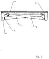
- Fig.2
- die Darstellung aus Fig.1 in Seitenansicht,
- Fig.3
- einen Schnitt durch die erfindungsgemäße Gelenkverbindung zwischen Gelenksockel und Beinrohr, wobei das Beinrohr vom Gelenksockel gelöst und damit abklappbar ist,
- Fig.4
- die Darstellung aus Fig.3 mit am Gelenksockel fixiertem Beinrohr,
- Fig.5
- oben eine Darstellung von Gelenksockel und Beinrohr im abgeklappten Zustand, und unten eine vergrößerte Darstellung des Bereiches, der oben mit "A" bezeichnet ist,
- Fig.6
- eine perspektivische Darstellung des T-Bolzens, und
- Fig.7
- oben eine Darstellung des Arretiersattels an der Tisch-Unterseite mit eingerastetem Arretierkörper des Beineinsatzes, und unten eine vergrößerte Darstellung des Bereiches, der oben mit "A" bezeichnet ist.
- 1
- Tischplatte
- 2
- Tischknoten
- 3
- Gelenksockel
- 4
- Beinrohr
- 5
- Arretierkörper
- 6
- Gleiterschraube
- 7
- Arretiersattel
- 8
- T-Bolzen
- 9
- Bremseinsatz
- 10
- Sockelfeder
- 11
- Ausnehmung
- 12
- Stapelschutz
- 13
- Gewindering
- 14
- Beineinsatz
- 15
- Beinfeder
- 16
- Anschlagscheibe
- 17
- Haltering
- 18
- Traverse
- 19
- Schrauben
- 20
- Bohrung
- 21
- Außengewinde des Gewinderinges 13
- 22
- Innengewinde des Gewinderinges 13
- 23
- Querstück
- 24
- oberer Schaft
- 25
- Gewinde auf dem T-Bolzen 8
- 26
- unterer Schaft
- 27
- Nut
- 28
- Bohrung
Claims (8)
- Tisch mit abklappbaren Beinen, bei welchem rohrförmige Beine (4) vorgesehen sind, die gelenkig mit an der Unterseite der Tischplatte (1) befestigten Gelenksockeln (3) verbunden sind, dadurch gekennzeichnet, dass für die gelenkige Verbindung des Beinrohres (4) mit dem Gelenksockel (3) ein T-Bolzen (8) vorgesehen ist, der mittels eines unter dem Druck einer Feder (10) stehenden Bremseinsatzes (9) mit seinem Querstück (23) in einem Lager des Gelenksockels (3) gehalten wird, und der mit seinem unteren Schaft (26) über ein Gewinde (25) mit einem Gewindering (13) verschraubt ist, auf dessen Außengewinde (21) das Beinrohr (4) mittels eines darin befestigten Beineinsatzes (14) durch Drehbewegung in Längsrichtung bewegbar ist.
- Tisch nach Anspruch 1, dadurch gekennzeichnet, dass der Gelenksockel (3) im Schwenkbereich des T-Bolzens (8) eine Ausnehmung (11) aufweist, in weiche der T-Bolzen (8) beim Abklappen des Beinrohres (4) eintritt, und durch welche das Querstück (23) des T-Bolzens (8) in das Lager im Gelenksockel (3) eingesetzt werden kann.
- Tisch nach Anspruch 1, dadurch gekennzeichnet, dass zwischen dem Gewindering (13) und dem Beineinsatz (14) eine Feder (15) vorgesehen ist, und das untere Ende des Beinrohres (4) einen Arretierkörper (5) aufweist, der im abgeklappten Zustand des Beinrohres (4) mit einer Nase in die Ausnehmung eines Arretiersattels (7) eingreift, wobei die Beinfeder (15) die Nase des Arretierkörpers (5) in die Ausnehmung des Arretiersattels (7) hineindrückt.
- Tisch nach Anspruch 3, dadurch gekennzeichnet, dass in dem Arretierkörper (5) eine Gleiterschraube (6) vorgesehen ist.
- Tisch nach Anspruch 1, dadurch gekennzeichnet, dass am gelenkseitigen Ende des Gelenksockels (3) ein als Stapelschutz (12) wirkender Ring eingesetzt ist, der beim Festschrauben des Beinrohres (4) in einer Ausnehmung des Beineinsatzes (14) aufgenommen wird.
- Tisch nach Anspruch 1, dadurch gekennzeichnet, dass der Gewindering (13) mit einem Innengewinde (22) kleinerer Ganghöhe auf dem Gewinde (25) des T-Bolzens (8) aufgeschraubt ist, und das Außengewinde (21) des Gewinderinges (13), über welches der Beineinsatz (14) bewegbar ist, eine größere Ganghöhe aufweist.
- Tisch nach Anspruch 6, dadurch gekennzeichnet, dass das Innengewinde (22) ein M10-Gewinde, und das Außengewinde (21) ein M24-Gewinde ist.
- Tisch nach Anspruch 1, dadurch gekennzeichnet, dass der Bremseinsatz (9) aus Kunststoff, vorzugsweise PA6, und der Beineinsatz (14) aus Aluminium-Druckguss bestehen.
Priority Applications (7)
| Application Number | Priority Date | Filing Date | Title |
|---|---|---|---|
| AT02022434T ATE361011T1 (de) | 2002-10-04 | 2002-10-04 | Tisch mit klappbaren beinen |
| EP02022434A EP1405580B1 (de) | 2002-10-04 | 2002-10-04 | Tisch mit klappbaren Beinen |
| ES02022434T ES2283493T3 (es) | 2002-10-04 | 2002-10-04 | Mesa con patas abatibles. |
| DE50210078T DE50210078D1 (de) | 2002-10-04 | 2002-10-04 | Tisch mit klappbaren Beinen |
| US10/643,951 US20040103828A1 (en) | 2002-10-04 | 2003-08-20 | Table with fold-away legs |
| CA002440489A CA2440489A1 (en) | 2002-10-04 | 2003-09-08 | Table with fold-away legs |
| MXPA03009016A MXPA03009016A (es) | 2002-10-04 | 2003-10-02 | Mesa con patas plegables. |
Applications Claiming Priority (1)
| Application Number | Priority Date | Filing Date | Title |
|---|---|---|---|
| EP02022434A EP1405580B1 (de) | 2002-10-04 | 2002-10-04 | Tisch mit klappbaren Beinen |
Publications (2)
| Publication Number | Publication Date |
|---|---|
| EP1405580A1 true EP1405580A1 (de) | 2004-04-07 |
| EP1405580B1 EP1405580B1 (de) | 2007-05-02 |
Family
ID=31985062
Family Applications (1)
| Application Number | Title | Priority Date | Filing Date |
|---|---|---|---|
| EP02022434A Expired - Lifetime EP1405580B1 (de) | 2002-10-04 | 2002-10-04 | Tisch mit klappbaren Beinen |
Country Status (7)
| Country | Link |
|---|---|
| US (1) | US20040103828A1 (de) |
| EP (1) | EP1405580B1 (de) |
| AT (1) | ATE361011T1 (de) |
| CA (1) | CA2440489A1 (de) |
| DE (1) | DE50210078D1 (de) |
| ES (1) | ES2283493T3 (de) |
| MX (1) | MXPA03009016A (de) |
Cited By (1)
| Publication number | Priority date | Publication date | Assignee | Title |
|---|---|---|---|---|
| DE202006007620U1 (de) * | 2006-05-11 | 2007-09-20 | Lau, Edgar | Klapptisch |
Families Citing this family (4)
| Publication number | Priority date | Publication date | Assignee | Title |
|---|---|---|---|---|
| US8182031B1 (en) * | 2010-01-27 | 2012-05-22 | Mackenzie Eric K | Poker kit with chairs and table |
| GB2569773B (en) * | 2017-10-13 | 2021-05-12 | Oxford Safety Components | Support apparatus |
| USD909786S1 (en) * | 2019-07-11 | 2021-02-09 | Rose Wavomba | Foldable table |
| FI20205462A1 (en) * | 2020-05-05 | 2021-11-06 | Leveko Oy | Joint and furniture |
Citations (1)
| Publication number | Priority date | Publication date | Assignee | Title |
|---|---|---|---|---|
| EP1050240A1 (de) * | 1999-05-06 | 2000-11-08 | Formenti & Giovenzana S.p.A. | Vorrichtung zum Verbinden eines klappbaren Stützbeines mit einem Möbelstück |
Family Cites Families (8)
| Publication number | Priority date | Publication date | Assignee | Title |
|---|---|---|---|---|
| US3126189A (en) * | 1964-03-24 | Latch | ||
| US1860644A (en) * | 1929-08-09 | 1932-05-31 | Lyon Metal Products Inc | Folding table and method of making the same |
| US1905219A (en) * | 1931-02-25 | 1933-04-25 | James V Crichton | Folding table |
| US2606802A (en) * | 1950-11-03 | 1952-08-12 | Inpyn Anthony | Folding leg support for furniture |
| US2799548A (en) * | 1956-05-10 | 1957-07-16 | Manuel E Arden | Socketed furniture leg receiving member |
| US2838353A (en) * | 1956-09-21 | 1958-06-10 | Roland C Emmert | Folding leg hinge and latch structure |
| US3026161A (en) * | 1958-09-25 | 1962-03-20 | Samuel R Mickelson | Leg locking device for folding tables |
| US2989356A (en) * | 1959-07-13 | 1961-06-20 | Virco Mfg Corp | Collapsible table leg and mounting therefor |
-
2002
- 2002-10-04 ES ES02022434T patent/ES2283493T3/es not_active Expired - Lifetime
- 2002-10-04 AT AT02022434T patent/ATE361011T1/de active
- 2002-10-04 DE DE50210078T patent/DE50210078D1/de not_active Expired - Lifetime
- 2002-10-04 EP EP02022434A patent/EP1405580B1/de not_active Expired - Lifetime
-
2003
- 2003-08-20 US US10/643,951 patent/US20040103828A1/en not_active Abandoned
- 2003-09-08 CA CA002440489A patent/CA2440489A1/en not_active Abandoned
- 2003-10-02 MX MXPA03009016A patent/MXPA03009016A/es unknown
Patent Citations (1)
| Publication number | Priority date | Publication date | Assignee | Title |
|---|---|---|---|---|
| EP1050240A1 (de) * | 1999-05-06 | 2000-11-08 | Formenti & Giovenzana S.p.A. | Vorrichtung zum Verbinden eines klappbaren Stützbeines mit einem Möbelstück |
Cited By (1)
| Publication number | Priority date | Publication date | Assignee | Title |
|---|---|---|---|---|
| DE202006007620U1 (de) * | 2006-05-11 | 2007-09-20 | Lau, Edgar | Klapptisch |
Also Published As
| Publication number | Publication date |
|---|---|
| ES2283493T3 (es) | 2007-11-01 |
| MXPA03009016A (es) | 2004-09-10 |
| ATE361011T1 (de) | 2007-05-15 |
| US20040103828A1 (en) | 2004-06-03 |
| EP1405580B1 (de) | 2007-05-02 |
| CA2440489A1 (en) | 2004-04-04 |
| DE50210078D1 (de) | 2007-06-14 |
Similar Documents
| Publication | Publication Date | Title |
|---|---|---|
| EP1338805B1 (de) | Lösbare Einsatz-Verbindungsanordnung für eine Halte-Nut | |
| DE69630706T2 (de) | Baumständer | |
| DE202018004631U1 (de) | Gestell, insbesondere in Form eines Dreibeins | |
| EP1915922B1 (de) | Klapptisch | |
| DE20019682U1 (de) | Griff für einen Schraubendreher | |
| EP1405580B1 (de) | Tisch mit klappbaren Beinen | |
| DE4336282A1 (de) | Verbindungselement für zwei sich kreuzende Rohre | |
| DE69631910T2 (de) | Einstellbarer adapter für eine unterschenkelprothese | |
| DE102008061854B4 (de) | Scharnier | |
| DE102012108622B4 (de) | Dreibein-Stützeinrichtung | |
| EP0617204B1 (de) | Möbel mit einem aus zylindrischen Elementen zusammengesetzten Tragwerk | |
| DE29500415U1 (de) | Bausatz für Kleinmöbel | |
| CH618143A5 (de) | ||
| DE19950804A1 (de) | Vorrichtung zur Halterung einer schwenkbaren Einrichtung | |
| DE20206837U1 (de) | Fahrradsattel | |
| DE102022126606B4 (de) | Transportables Klettergestell, insbesondere für Kleinkinder | |
| EP1523905B1 (de) | Tisch mit klappbaren Beinen | |
| EP2460965B1 (de) | Gebremstes Lager sowie Möbelstück, insbesondere Klapptisch | |
| DE10138065B4 (de) | Federbelasteter Umleggriff | |
| DE10027430C2 (de) | Verbindungsknotenelemente und Verbindungsstäbe für den Aufbau von Stab-Knoten-Raumfachwerken | |
| DE10203330C1 (de) | Verbindungseinrichtung für Tische, Barhocker und dergleichen | |
| DE202025102648U1 (de) | Schnell aufbaubarer, klappbarer Kinderhochstuhl | |
| DE3831868A1 (de) | Klapp- oder faltrad in einzelteilen zur selbstmontage | |
| DE20215603U1 (de) | Verstellbare Fußstütze für ein Fahrrad | |
| DE102006001786A1 (de) | Winkel-Gelenkteil, insbesondere für einen Banner- oder Fahnenträger |
Legal Events
| Date | Code | Title | Description |
|---|---|---|---|
| PUAI | Public reference made under article 153(3) epc to a published international application that has entered the european phase |
Free format text: ORIGINAL CODE: 0009012 |
|
| AK | Designated contracting states |
Kind code of ref document: A1 Designated state(s): AT BE BG CH CY CZ DE DK EE ES FI FR GB GR IE IT LI LU MC NL PT SE SK TR |
|
| AX | Request for extension of the european patent |
Extension state: AL LT LV MK RO SI |
|
| 17P | Request for examination filed |
Effective date: 20040511 |
|
| AKX | Designation fees paid |
Designated state(s): AT BE BG CH CY CZ DE DK EE ES FI FR GB GR IE IT LI LU MC NL PT SE SK TR |
|
| GRAP | Despatch of communication of intention to grant a patent |
Free format text: ORIGINAL CODE: EPIDOSNIGR1 |
|
| GRAS | Grant fee paid |
Free format text: ORIGINAL CODE: EPIDOSNIGR3 |
|
| GRAA | (expected) grant |
Free format text: ORIGINAL CODE: 0009210 |
|
| AK | Designated contracting states |
Kind code of ref document: B1 Designated state(s): AT BE BG CH CY CZ DE DK EE ES FI FR GB GR IE IT LI LU MC NL PT SE SK TR |
|
| PG25 | Lapsed in a contracting state [announced via postgrant information from national office to epo] |
Ref country code: FI Free format text: LAPSE BECAUSE OF FAILURE TO SUBMIT A TRANSLATION OF THE DESCRIPTION OR TO PAY THE FEE WITHIN THE PRESCRIBED TIME-LIMIT Effective date: 20070502 |
|
| REG | Reference to a national code |
Ref country code: GB Ref legal event code: FG4D Free format text: NOT ENGLISH |
|
| REG | Reference to a national code |
Ref country code: CH Ref legal event code: EP |
|
| REG | Reference to a national code |
Ref country code: IE Ref legal event code: FG4D Free format text: LANGUAGE OF EP DOCUMENT: GERMAN |
|
| REF | Corresponds to: |
Ref document number: 50210078 Country of ref document: DE Date of ref document: 20070614 Kind code of ref document: P |
|
| GBT | Gb: translation of ep patent filed (gb section 77(6)(a)/1977) |
Effective date: 20070627 |
|
| PG25 | Lapsed in a contracting state [announced via postgrant information from national office to epo] |
Ref country code: SE Free format text: LAPSE BECAUSE OF FAILURE TO SUBMIT A TRANSLATION OF THE DESCRIPTION OR TO PAY THE FEE WITHIN THE PRESCRIBED TIME-LIMIT Effective date: 20070802 |
|
| ET | Fr: translation filed | ||
| REG | Reference to a national code |
Ref country code: ES Ref legal event code: FG2A Ref document number: 2283493 Country of ref document: ES Kind code of ref document: T3 |
|
| REG | Reference to a national code |
Ref country code: IE Ref legal event code: FD4D |
|
| PG25 | Lapsed in a contracting state [announced via postgrant information from national office to epo] |
Ref country code: CZ Free format text: LAPSE BECAUSE OF FAILURE TO SUBMIT A TRANSLATION OF THE DESCRIPTION OR TO PAY THE FEE WITHIN THE PRESCRIBED TIME-LIMIT Effective date: 20070502 Ref country code: BG Free format text: LAPSE BECAUSE OF FAILURE TO SUBMIT A TRANSLATION OF THE DESCRIPTION OR TO PAY THE FEE WITHIN THE PRESCRIBED TIME-LIMIT Effective date: 20070802 Ref country code: IE Free format text: LAPSE BECAUSE OF FAILURE TO SUBMIT A TRANSLATION OF THE DESCRIPTION OR TO PAY THE FEE WITHIN THE PRESCRIBED TIME-LIMIT Effective date: 20070502 Ref country code: DK Free format text: LAPSE BECAUSE OF FAILURE TO SUBMIT A TRANSLATION OF THE DESCRIPTION OR TO PAY THE FEE WITHIN THE PRESCRIBED TIME-LIMIT Effective date: 20070502 Ref country code: PT Free format text: LAPSE BECAUSE OF FAILURE TO SUBMIT A TRANSLATION OF THE DESCRIPTION OR TO PAY THE FEE WITHIN THE PRESCRIBED TIME-LIMIT Effective date: 20071002 |
|
| PG25 | Lapsed in a contracting state [announced via postgrant information from national office to epo] |
Ref country code: SK Free format text: LAPSE BECAUSE OF FAILURE TO SUBMIT A TRANSLATION OF THE DESCRIPTION OR TO PAY THE FEE WITHIN THE PRESCRIBED TIME-LIMIT Effective date: 20070502 |
|
| PLBE | No opposition filed within time limit |
Free format text: ORIGINAL CODE: 0009261 |
|
| STAA | Information on the status of an ep patent application or granted ep patent |
Free format text: STATUS: NO OPPOSITION FILED WITHIN TIME LIMIT |
|
| 26N | No opposition filed |
Effective date: 20080205 |
|
| BERE | Be: lapsed |
Owner name: SEDUS STOLL A.G. Effective date: 20071031 |
|
| PG25 | Lapsed in a contracting state [announced via postgrant information from national office to epo] |
Ref country code: GR Free format text: LAPSE BECAUSE OF FAILURE TO SUBMIT A TRANSLATION OF THE DESCRIPTION OR TO PAY THE FEE WITHIN THE PRESCRIBED TIME-LIMIT Effective date: 20070803 |
|
| PG25 | Lapsed in a contracting state [announced via postgrant information from national office to epo] |
Ref country code: MC Free format text: LAPSE BECAUSE OF NON-PAYMENT OF DUE FEES Effective date: 20071031 |
|
| PG25 | Lapsed in a contracting state [announced via postgrant information from national office to epo] |
Ref country code: BE Free format text: LAPSE BECAUSE OF NON-PAYMENT OF DUE FEES Effective date: 20071031 |
|
| PG25 | Lapsed in a contracting state [announced via postgrant information from national office to epo] |
Ref country code: EE Free format text: LAPSE BECAUSE OF FAILURE TO SUBMIT A TRANSLATION OF THE DESCRIPTION OR TO PAY THE FEE WITHIN THE PRESCRIBED TIME-LIMIT Effective date: 20070502 |
|
| PG25 | Lapsed in a contracting state [announced via postgrant information from national office to epo] |
Ref country code: CY Free format text: LAPSE BECAUSE OF FAILURE TO SUBMIT A TRANSLATION OF THE DESCRIPTION OR TO PAY THE FEE WITHIN THE PRESCRIBED TIME-LIMIT Effective date: 20070502 |
|
| PG25 | Lapsed in a contracting state [announced via postgrant information from national office to epo] |
Ref country code: LU Free format text: LAPSE BECAUSE OF NON-PAYMENT OF DUE FEES Effective date: 20071004 |
|
| PG25 | Lapsed in a contracting state [announced via postgrant information from national office to epo] |
Ref country code: TR Free format text: LAPSE BECAUSE OF FAILURE TO SUBMIT A TRANSLATION OF THE DESCRIPTION OR TO PAY THE FEE WITHIN THE PRESCRIBED TIME-LIMIT Effective date: 20070502 |
|
| REG | Reference to a national code |
Ref country code: DE Ref legal event code: R082 Ref document number: 50210078 Country of ref document: DE |
|
| REG | Reference to a national code |
Ref country code: FR Ref legal event code: PLFP Year of fee payment: 14 |
|
| REG | Reference to a national code |
Ref country code: FR Ref legal event code: PLFP Year of fee payment: 15 |
|
| PGFP | Annual fee paid to national office [announced via postgrant information from national office to epo] |
Ref country code: NL Payment date: 20161019 Year of fee payment: 15 Ref country code: CH Payment date: 20161020 Year of fee payment: 15 Ref country code: DE Payment date: 20161031 Year of fee payment: 15 Ref country code: FR Payment date: 20161020 Year of fee payment: 15 Ref country code: GB Payment date: 20161020 Year of fee payment: 15 |
|
| PGFP | Annual fee paid to national office [announced via postgrant information from national office to epo] |
Ref country code: IT Payment date: 20161024 Year of fee payment: 15 Ref country code: AT Payment date: 20161020 Year of fee payment: 15 Ref country code: ES Payment date: 20161011 Year of fee payment: 15 |
|
| REG | Reference to a national code |
Ref country code: DE Ref legal event code: R119 Ref document number: 50210078 Country of ref document: DE |
|
| REG | Reference to a national code |
Ref country code: CH Ref legal event code: PL |
|
| REG | Reference to a national code |
Ref country code: NL Ref legal event code: MM Effective date: 20171101 |
|
| REG | Reference to a national code |
Ref country code: AT Ref legal event code: MM01 Ref document number: 361011 Country of ref document: AT Kind code of ref document: T Effective date: 20171004 |
|
| GBPC | Gb: european patent ceased through non-payment of renewal fee |
Effective date: 20171004 |
|
| REG | Reference to a national code |
Ref country code: FR Ref legal event code: ST Effective date: 20180629 |
|
| PG25 | Lapsed in a contracting state [announced via postgrant information from national office to epo] |
Ref country code: NL Free format text: LAPSE BECAUSE OF NON-PAYMENT OF DUE FEES Effective date: 20171101 Ref country code: DE Free format text: LAPSE BECAUSE OF NON-PAYMENT OF DUE FEES Effective date: 20180501 Ref country code: GB Free format text: LAPSE BECAUSE OF NON-PAYMENT OF DUE FEES Effective date: 20171004 Ref country code: LI Free format text: LAPSE BECAUSE OF NON-PAYMENT OF DUE FEES Effective date: 20171031 Ref country code: CH Free format text: LAPSE BECAUSE OF NON-PAYMENT OF DUE FEES Effective date: 20171031 |
|
| PG25 | Lapsed in a contracting state [announced via postgrant information from national office to epo] |
Ref country code: AT Free format text: LAPSE BECAUSE OF NON-PAYMENT OF DUE FEES Effective date: 20171004 Ref country code: FR Free format text: LAPSE BECAUSE OF NON-PAYMENT OF DUE FEES Effective date: 20171031 |
|
| PG25 | Lapsed in a contracting state [announced via postgrant information from national office to epo] |
Ref country code: IT Free format text: LAPSE BECAUSE OF NON-PAYMENT OF DUE FEES Effective date: 20171004 |
|
| REG | Reference to a national code |
Ref country code: ES Ref legal event code: FD2A Effective date: 20181220 |
|
| PG25 | Lapsed in a contracting state [announced via postgrant information from national office to epo] |
Ref country code: ES Free format text: LAPSE BECAUSE OF NON-PAYMENT OF DUE FEES Effective date: 20171005 |