EP1404595B1 - Lagersystem mit zugriffskontrollsystem - Google Patents
Lagersystem mit zugriffskontrollsystem Download PDFInfo
- Publication number
- EP1404595B1 EP1404595B1 EP02760095A EP02760095A EP1404595B1 EP 1404595 B1 EP1404595 B1 EP 1404595B1 EP 02760095 A EP02760095 A EP 02760095A EP 02760095 A EP02760095 A EP 02760095A EP 1404595 B1 EP1404595 B1 EP 1404595B1
- Authority
- EP
- European Patent Office
- Prior art keywords
- storage
- access
- region
- storage system
- barrier
- Prior art date
- Legal status (The legal status is an assumption and is not a legal conclusion. Google has not performed a legal analysis and makes no representation as to the accuracy of the status listed.)
- Expired - Lifetime
Links
- 238000013475 authorization Methods 0.000 claims abstract description 26
- 230000004888 barrier function Effects 0.000 claims description 41
- 230000000903 blocking effect Effects 0.000 claims description 5
- 238000001514 detection method Methods 0.000 claims description 4
- 238000013461 design Methods 0.000 claims description 3
- 230000000717 retained effect Effects 0.000 claims 3
- 230000001419 dependent effect Effects 0.000 claims 1
- 239000011232 storage material Substances 0.000 abstract description 7
- 230000008021 deposition Effects 0.000 abstract 1
- 239000000969 carrier Substances 0.000 description 16
- 238000000034 method Methods 0.000 description 5
- 239000000463 material Substances 0.000 description 3
- 238000012546 transfer Methods 0.000 description 3
- 230000032258 transport Effects 0.000 description 3
- 230000009977 dual effect Effects 0.000 description 2
- 230000001427 coherent effect Effects 0.000 description 1
- 238000011161 development Methods 0.000 description 1
- 238000007726 management method Methods 0.000 description 1
- 238000012946 outsourcing Methods 0.000 description 1
Images
Classifications
-
- B—PERFORMING OPERATIONS; TRANSPORTING
- B65—CONVEYING; PACKING; STORING; HANDLING THIN OR FILAMENTARY MATERIAL
- B65G—TRANSPORT OR STORAGE DEVICES, e.g. CONVEYORS FOR LOADING OR TIPPING, SHOP CONVEYOR SYSTEMS OR PNEUMATIC TUBE CONVEYORS
- B65G1/00—Storing articles, individually or in orderly arrangement, in warehouses or magazines
- B65G1/02—Storage devices
- B65G1/04—Storage devices mechanical
- B65G1/137—Storage devices mechanical with arrangements or automatic control means for selecting which articles are to be removed
Definitions
- the invention relates to a storage system comprising a storage area for storage of Storage goods in at least one storage place, one from the storage area spatially separated Access area for accessing the stored goods in the access area Conveyor for transporting the stored goods between the storage bin and the Access area, and a conveyor shaft.
- the conveying means in a conveying direction is received back and forth and movable in the conveying direction between the Storage area and the access area is arranged.
- a generic storage system is known for example from DE 92 13 478 U1.
- a storage lift is shown and described in which a Computer-controlled loading and unloading device in one between two Regalchulen arranged shaft is guided.
- the stored goods are on load carriers in stored on individual shelves.
- the loading and unloading device promotes that Storage goods from its storage bins in the individual shelves to a loading and unloading Withdrawal opening and back. Through the loading and removal opening is the Stored or outsourced goods.
- EP 1 061 013 A1 shows a circulation rack according to the patemoster principle, in which a vertical access opening is provided with a locking device
- the Closing device has at least two oppositely disposed closing element on, which are displaceable in the horizontal direction.
- the present invention is therefore the task basis, a storage system with a storage area and a local storage area separate access area and a system for its management, in which the access to at least a part of the stored stock is limited.
- this object is achieved by an access area Access control system with a lock released as a substantially horizontal Platform trained and depending on an access authorization code of a User at least partially from a lock state in which the access to the stored goods is locked, is in a release state can be transferred, in which the Access to the stored goods is released.
- the inventive access control system of the storage system the access is free only to that part of the stored goods to which a user has his access authorization can prove by means of the associated access authorization code.
- the lock fulfills a dual function according to the invention as a horizontal platform and thus Working surface of the storage system and as part of the access control system of the storage system.
- the solution according to the invention is not, as in the conventional storage systems with separate access and storage area, the stored goods in one above the platform promoted lying access area.
- the access area is rather below the Platform arranged. In the place of the access area is at the from the State of the art storage system usually a storage area.
- the stored goods are stored on carriers, such as containers or trays, stored and transported together with the goods carrier in the access area.
- the load-carriers can have compartments for this, in which different storage goods kept separate from each other. Is such a load-carrier in the Transport area, so may according to an advantageous embodiment, the storage system be able to access only those parts of the compartments or the stored goods to which the user is entitled according to the access authorization code is. These individual subareas may vary depending on the arrangement of the stored goods or compartments be arranged on the load-carrier coherent or separated.
- a structurally particularly simple solution for the access control system is then obtained when the barrier is located between the stored goods and the user.
- the barrier can also be used as a bulkhead, cover or door or a combination be formed by bulkheads, covers or doors that are locked in the locked state and is open in the release state or are.
- the storage system To store stored goods of different sizes, the storage system according to a advantageous embodiment with a size detecting means for detecting the dimensions be provided of the stored goods. For example, from such a size detection means during storage, the stored product height is recorded and stored. In Depending on the dimensions, the stored material is in the access area in one corresponding distance from the lock transferred. In this embodiment, so is the Location of the access area depending on the size of the stored goods to which the access is released shall be. In this embodiment, collisions of the stored goods with the Lock avoided and security against abuse increased, as between the stored goods and the lock remain only small column.
- the Barrier has a plurality of part locks, each through a portion of the Access range depending on the access authorization code from the lock state to the Release state is feasible.
- a part lock is a compartment of a in Access area assigned in an access position storage goods carrier.
- the size of the part locks is advantageously sized so that a part lock or a Combination of adjoining part locks exactly one compartment of a goods carrier blocked.
- the part locks can advantageously be designed as flaps which are pivotable or displaceable held at the lock.
- a further, second, access area for the stored goods exhibit.
- This second access area differs in functional terms from the first access area by allowing access to the stored goods in a second Access position substantially without the action of the access control system allows.
- the second access area can be distinguished by its from the first Differentiate Access Area from Different Location: In the second access area this is Stored goods between the lock and the user arranged so that the user in the Has substantially free access to the stored goods.
- the use of the second access area allows the storage and retrieval of bulky stored goods due to its Dimensions would not fit through the lock or the part locks.
- an inner lock associated with the second access area and between the second access area and the storage area.
- These Lock is used to transport the stored goods from the storage area to the second access area opened and closed as soon as the stored goods are in the second access position located. By this lock an entry hole is blocked by the stored goods is introduced by the funding in the second access area.
- the second lock may be formed by the lock for the first access area, so that the lock fulfills a dual function with regard to the two access areas.
- a second lock in addition to the lock of the first blocking area be provided, which can be operated independently of the first lock.
- an outer barrier may be provided, which is the second Access area assigned and between the second access area and the user is arranged. Through the outer barrier, access to the interior of the storage system is locked when the inner lock is open.
- the second access area as a kind Sluice operated so that when transporting stored goods between the second Access area and the storage area at any time access to the interior of the storage system consists.
- the inner barrier closes the storage area-side entry opening, while the outer barrier is open.
- a load-carrier by the conveyor transported from the storage area in the access area, so first the outer lock closed and then opened the inner lock, so that the load-carrier through the Entry opening can be transported in the access area.
- the inner barrier is closed and then the outer Lock open. In this position then the access to the goods carrier is possible, the However, access to the storage area inside is blocked by the inner lock.
- this process can be performed in the reverse order be carried out when the stored goods to be stored in the access area has been.
- the access control system can provide access to the stored goods in a further advantageous Design also before the access of the conveyor to the stored goods in the storage area or to the stored goods in the access area. For example, if that a user for the removal of the entire stored goods on a load-carrier has no authorization, so in this embodiment, the storage system is the Users only signal the lack of access authorization, but the stored goods Do not remove from the access area or the storage area.
- the lock of the first Access area at the same time serve as an outer lock of the second access area.
- the lock of the first access area as a whole in the Release state are released to release the stored goods.
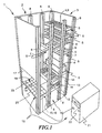
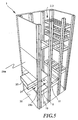
- FIG. 1 First, structure and function of a storage system 1 according to the invention with reference to the figure 1 described.
- FIG. 1 those facing the viewer are shown Sidewalls omitted to allow insight into the interior of the storage system 1.
- the storage system 1 has two shaft-shaped storage areas 2, 3 in the form of shelf columns on, in which stored goods 4 is stored.
- the number of storage areas in the storage system is arbitrary.
- the storage areas 2, 3 in the form of a shelf column with in vertical Direction superimposed, stationary storage bins 5 constructed.
- the respective storage areas 5 of the storage areas 2, 3 is the stored goods 4 by load-carrier 6, 7 held, which are received in corresponding storage stands 8.
- the storage frame 8 forms at the respective storage bins 5 rail-shaped holding means for the Goods carrier 6, 7 from.
- the load-carriers 6, 7 can be designed differently. For example, you can the load-carrier 6 be provided with compartments 9, in each of which different storage goods sorted are stored. The size and arrangement of the compartments 9 can be in Differ depending on the stored goods. A part of the load-carriers 6, 7 can also be designed as shelves 7, whose shape is essentially a platform or a shelf. On the trays 7 stored goods 4 can directly or in load carriers 6 are stored.
- a conveyor shaft 10 is arranged, in which a Conveyor 11 moves.
- these serve in each case the delivery shaft facing storage stands 8 at the same time as guides for the funding 11.
- the conveyor 11 along the storage bins 5 - in Fig. 1, this is essentially in vertical direction up and down - out.
- the conveyor 11 is with a gripping system (not visible in Fig. 1), as for example is known in the art, equipped.
- the subsidy works each with a storage goods carrier 6, 7 together and moves the load-carriers of the respective Storage bin 5 in the conveyor shaft 10 and vice versa.
- the gripping means can, for example be designed as a circumferential finger on the conveyor, which in a corresponding Stock-goods-side finger holder engages. Also hydraulically operated telescopic arms can serve as gripping means.
- the conveyor 11 together with the gripping system is controlled automatically by a control device, not shown.
- the storage system 1 is shown in a state in which just a load-carrier 12 from the conveyor 11 from the associated storage space 13 in the conveyor shaft 10th is pulled.
- the compartments 14 of the storage goods carrier 12 are larger and deeper than those of the load-carrier 6, so that in the subjects 14 larger Storage goods can be stored.
- a size detection means (not shown) by which at least the height and / or other dimensions the stored goods 4 and the load-carriers 6, 7, 12 are detected.
- the conveying means 11 transports stored goods 4 or load-carriers 6, 7 between the respective ones Bins 5 in the storage areas 2, 3 and an access position 15 in one locally from the storage area 2, 3 separate access area 16, which in Figure 1 schematically with Dotted lines is shown.
- the access area 16 is an access to the stored goods 4 and the Load-carrier 6, 7 from outside the storage system 1, d. H. a storage and retrieval of Storage goods and load-carriers, possible. Access to the stored goods 4 in the access area 16 takes place through the access opening 17 in an access direction 18.
- an access control system 19 which is assigned to the access area 16, the Access to the stored goods in access area 16 controlled enabled or disabled.
- the Access control system has for this purpose a barrier 20, which is above the access area 16, that is, between a user and the access area 16, is arranged.
- the barrier 20 serves as a platform of the storage system and prevents unauthorized Access to stored goods 4 in access area 16.
- the access area 16 with the Access position 15 for the stored goods below the platform 20.
- the size detection means By the size detection means, the height of the stored material 4 or the storage goods carrier 6, 7 detected and stored. When swapping out this information retrieved again and the stored goods 4 and the load-carrier 6, 7 from the funding 11 in a corresponding distance below the lock 20 in the access position 15th the access area 16 transferred.
- the access control system 19 has, in addition to the barrier 20, a control module 21 with a Input device 22, through which a user has a predetermined access authorization code enters.
- a control module 21 with a Input device 22 through which a user has a predetermined access authorization code enters.
- the input device 22 for example, as a card reader for chip or magnetic cards, as Keyboard, scanner or designed as a non-contact transponder system be.
- the access authorization code allows the storage system 1 to be automatically guided Inventory list, in each of which the storage bin 5 and a release code of the stored Lagerguts are stored, determine whether the user is entitled to the respective access is. For this purpose, the access control system 19 of the stored goods 3 assigned Release code and the access authorization code associated with the user compared. Depending on the result of this comparison, the access control system 19, the lock 20 at least partially from a locked state, in the because lack of access authorization, no access to the stored goods is possible, in a release state in which due to an existing access authorization of the user Access to the stored goods in the access area 16 is possible.
- the access authorization and release codes can be hierarchically staggered, so that an access authorization code with a high access permission to access the Lagergütern 4 or storage product carriers 6, 5 allows the lower with a release code Authorization are provided.
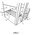
- the access can be carried out at storage goods carriers 6, which receive several stored goods, depending on from the access authorization code by the access control system 19 to only a part of stored goods 4 are limited in the load-carrier 6, when the load-carrier 6 is in the access position 15.
- the load-carrier 6 is at least partially, in FIG. 2 completely, through the barrier 20 of the access control system 19 covered, so that a free storage and retrieval of stored goods 4, bypassing the Access control system 19 is not possible.
- each partial lock 23 is as a separately controllable Cover configured, depending on the access authorization code the user and the release code of the stored goods access to the underlying Releases or locks the scope independently of other partial locks.
- the part locks 23 The barrier 20 forms a field which together covers one side of the access area. The Dimensions of the field correspond approximately to the dimensions of a load-carrier.
- the part locks 23 are in the illustrated embodiment as a flap-shaped Lid configured, arranged side by side in several parallel rows and by webs, in which the pivotal bearings of the lid are added, from each other are separated.
- FIG. 2 shows how two part locks 24a, 24b are opened.
- the partial lock 24a is for accessing a stored product 25 in the fully unfolded state and the partial lock 24b shown in the partially unfolded state.
- the part locks are each the subjects 9 associated with a storage goods carrier and arranged so that they are the compartments 9 of a Cover the load-carrier in the access position as completely as possible.
- the dimensions of the compartments 9 and that of a single part lock 23 covered Range are particularly coordinated so that by opening a part lock 23 or a combination of adjacent part locks 23 access exactly one tray at a time 9 or exactly one combination of adjacent ones Compartments 9 with the same release code is possible.
- This configuration is prevents access to compartments when opening a partial lock 23, for which the user has no access rights, but otherwise partly in the of the Partial lock 23 would protested shared area.
- the size of a part lock 23 corresponds So the size of a tray 9 or an integer multiple of this size.
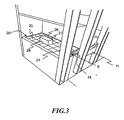
- FIG. 3 shows the storage system 1 or the access control system in a state in which in the case of an access authorization code modified with respect to FIG the adjacent part locks 26, 27 are released.
- the access to the stored goods 28 is free.
- the partial lock in Figure 3 due to a different conditional access signal 24 locked because in the process shown in Figure 3, the user is not authorized for access to the covered by the part lock 23 stored goods 25 has.
- the storage material 28 that has just been removed is larger than that Stored goods 25 of Figure 2. Accordingly, for access to the stored goods 28, the two adjacent lids 26 and 27 are released. To access the adjacent compartments in the load-carrier 6 in the access position 15 to prevent corresponds the size of the released by the part locks 26, 27 area exactly the Size of the compartment in which the stored goods 28 is received.
- the security of the access control system 19 against manipulation from the outside can thereby be increased again that between the subjects 9 and the lock 20 a possible there is little gap, the removal of stored goods or the manipulation the lock is prevented by the gap.
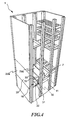
- FIGS. 4 and 5 show a second embodiment of the storage system.
- Figures 4 and 5 are for elements whose structure and function the elements of the embodiment of Figures 1 to 3, the same reference numerals.
- FIGS. 4 and 5 The embodiment of Figures 4 and 5 is in addition to the barrier 20 with an outer Lock 29a and an inner lock 29b and a second access area 30th Mistake.
- the second access area 30 is shown in dotted lines in FIGS. 4 and 5.
- the locks 29a, 29b act together in the manner of a lock system and are the assigned to second access area 30.
- the second access area 30 is located above the lock 20 and therefore allows access to the stored goods without impact the access control system.
- the front or outer barrier 29a is as a top to bottom, transverse to the direction of access 18 sliding door designed essentially in the plane of the Access opening 17 is displaceable.
- the inner barrier 29b is at the storage areas 2, 3 facing side of the access area 16 and also as a sliding door designed.
- the lock 17 blocks an entry opening 31, through the stored goods. 4 above the access control system 19 from the conveyor 11 to a second access position 32 is transported in the second access area 30.
- the second access area 30 can be used to load goods carriers with stored goods by a user with high access authorization or for storage and retrieval of bulky stored goods that can not pass through the barrier 20 of the first access area 16, be used.
- the bulky item 33 on the tray 7 is by the conveyor 8 from the storage bin brought into the second access area 16 above the barrier 20.
- the outer lock 29 a is first moved down and the Access opening 17 closed. Only then is the inner barrier 29b moved upwards, to release the entry port 31, through which the individual goods 33 from the conveyor 11 moves to the second access position 32 within the access area 16 becomes.
- the lock 19 serves as a support, on which the item 33 is stored with or without tray 7.
- the inner barrier 29b becomes moved down and closed the entry port 31. Subsequently, the outer lock 29a opened to release the access to the individual goods 33.
- the process is carried out in reverse order and the empty tray 7 again transferred to its associated storage area 2, 3:
- the outer barrier 29b closes the access opening 17, whereupon the inner barrier 29a the entry port 31 releases; then the conveyor 11 pulls the tray 7 in the Delivery shaft 10 and puts the empty tray 5 in the corresponding storage area 2, 3 from.
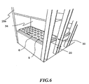
- FIG. 6 shows a third exemplary embodiment of a storage system.
- the same reference numerals in FIG. 6 for elements whose structure and function correspond to the elements described above Embodiments corresponds, the same reference numerals.
- the access control system 19 of Figure 6 designed as a retrofit kit, in an existing, conventional Storage system 1 was installed.
- fastening means (not shown) to provided the lock, which are not solvable after mounting from the outside, so that a Abusive removal of the access control system 19 and the lock 20 prevented is.
- the storage system 1 of Figure 6 also has in contrast to the embodiment of Figures 4 and 5 no additional inner barrier 29b, but only an outer barrier 29a on.
- a fixed wall 34 which opposes the access opening 17 of the access area 30.
- the lock 20 serves as a barrier for the same time first access area 16 and as an inner barrier for the second access area. In this Case closes the barrier 20 during the transfer of stored goods in the second access area the entry port for the second access area and forms together with the outer barrier 29b the lock area.
- the locks 20 and 29b act as the locks 29a and 29b together.
Description
- Figur 1
- eine perspektivische Ansicht eines ersten Ausführungsbeispiels eines erfindungsgemäßen Lagersystems;
- Figur 2
- das Lagersystem der Figur 1 mit einem Lagergutträger bei der Entnahme von Lagergut;
- Figur 3
- das Lagersystem der Figur 1 mit einem Lagergutträger beim Einlagern von Lagergut;
- Figur 4
- ein weiteres Ausführungsbeispiel eines Lagersystems mit einem zweiten Zugriffsbereich und einem Schleusensystem;
- Figur 5
- das Lagersystem der Figur 4 bei der Entnahme von Lagergut aus der zweiten Zugriffsposition;
- Figur 6
- ein drittes Ausführungsbeispiel des Lagersystems.
Claims (17)
- Lagersystem (1) umfassend einen Lagerbereich (2, 3) zur Einlagerung von Lagergut (4) in wenigstens einen Lagerplatz (5), einen vom Lagerbereich (2, 3) örtlich getrennten Zugriffsbereich (16) zum Zugriff auf das im Zugriffsbereich befindliche Lagergut, ein Fördermittel (11) zum Transport des Lagerguts zwischen dem Lagerplatz und dem Zugriffsbereich, und einen Förderschacht (10), in dem das Fördermittel (11) in einer Förderrichtung hin- und her beweglich aufgenommen ist und der in Förderrichtung zwischen dem Lagerbereich und dem Zugriffsbereich angeordnet ist, gekennzeichnet durch ein dem Zugriffsbereich zugeordnetes Zugriffskontrollsystem (19) mit einer Sperre (20), die als eine Im Wesentlichen horizontale Plattform ausgebildet und in Abhängigkeit von einem Zugriffsberechtigungscode eines Benutzers zumindest abschnittsweise von einem Sperrzustand, in weichem der Zugriff auf das Lagergut versperrt ist, in einen Freigabezustand überführbar ist, in welchem der Zugriff auf das Lagergut freigegeben ist.
- Lagersystem (1) nach Anspruch 1 dadurch gekennzeichnet, dass die Sperre (20) zwischen Benutzer und Lagergut (4) angeordnet ist.
- Lagersystem (1) nach einem der oben genannten Ansprüche, dadurch gekennzeichnet, dass die Sperre (20) zur Freigabe des Zugriffsbereichs (16) beweglich am Lagersystem (1) gehalten ist.
- Lagersystem (1) nach einem der oben genannten Ansprüche, dadurch gekennzeichnet, dass die Sperre (20) eine Mehrzahl von Teilsperren (23) aufweist, die jeweils in Abhängigkeit vom Zugriffsberechtigungscode von einem Freigabezustand in einen Sperrzustand überführbar sind und durch die im Sperrzustand jeweils ein Teilabschnitt des Zugriffsbereichs (15) versperrt ist.
- Lagersystem (1) nach Anspruch 4, dadurch gekennzeichnet, dass eine Teilsperre (23) jeweils einem Fach (9) des Lagergutträgers (6) im Zugriffsbereich (16) zugeordnet ist.
- Lagersystem (1) nach Anspruch 4 oder 5, mit wenigstens einem mit Fächern (9) versehenen Lagergutträger (6), dadurch gekennzeichnet, dass die Größe eines Faches (9) der Größe des von einer Teilsperre (23) verschlossenen Teilbereichs oder einem ganzzahligen Vielfachen dieser Größe entspricht
- Lagersystem (1) nach einem der Ansprüche 4 bis 6, dadurch gekennzeichnet, dass die Teilsperren (23) im Wesentlichen klappenförmig ausgebildet sind.
- Lagersystem (1) nach einem der oben genannten Ansprüche, dadurch gekennzeichnet, dass das Lagersystem (1) einen zweiten Zugriffsbereich (30) aufweist, in den das Lagergut (4) im Betrieb durch das Fördermittel (11) förderbar ist.
- Lagersystem (1) nach Anspruch 8, dadurch gekennzeichnet, dass im zweiten Zugriffsbereich (32) das Lagergut (4) im Wesentlichen ohne Einwirkung des Zugriffskontrollsystems (19) gehalten ist.
- Lagersystem (1) nach Anspruch 8 oder 9, dadurch gekennzeichnet, dass das Lagergut (4) im zweiten Zugriffsbereich (30) zwischen der Sperre (20) und dem Benutzer gehalten ist.
- Lagersystem (1) nach einem der Ansprüche 8 bis 10, dadurch gekennzeichnet, dass die Sperre (20) zwischen der ersten Zugriffsposition (15) und der zweiten Zugriffsposition (32) angeordnet ist.
- Lagersystem (1) nach einem der oben genannten Ansprüche, dadurch gekennzeichnet, dass das Lagersystem eine innere Sperre (29b) aufweist, die zwischen dem zweiten Zugriffsbereich (30) und dem Lagerbereich angeordnet ist.
- Lagersystem (1) nach einem der oben genannten Ansprüche, dadurch gekennzeichnet, dass das Lagersystem (1) eine äußere Sperre (29a) aufweist, die zwischen dem Benutzer und dem zweiten Zugriffsbereich (30) angeordnet ist.
- Lagersystem (1) nach einem der oben genannten Ansprüche, dadurch gekennzeichnet, dass das Lagersystem (1) ein Größenerfassungsmittel aufweist, durch das die Größe des Lagerguts (4) erfassbar ist, und dass das Lagergut (4) im Zugriffsbereich (16) in einer von seiner Größe abhängigen Zugriffsposition (15) angeordnet ist.
- Lagersystem (1) nach einem der oben genannten Ansprüche, dadurch gekennzeichnet, dass die Lagerplätze (5) stationär im Lagerbereich angeordnet sind.
- Lagersystem (1) nach einem der oben genannten Ansprüche, dadurch gekennzeichnet, dass der Lagerbereich (2, 3) durch sich gegenüberliegende Regalsäulen gebildet ist, zwischen denen der Förderschacht (10) angeordnet ist.
- Zugriffskontrollsystem (19) zum Einbau in ein Lagersystem (1) mit einem Lagerbereich (2, 3) zur Einlagerung von Lagergut (4) in wenigstens einem Lagerplatz (5), mit einem vom Lagerbereich (2, 3) örtlich getrennten Zugriffsbereich (16) zum Zugriff auf das sich im Zugriffsbereich befindliche Lagergut (4) sowie mit einem Fördermittel (11) zum Transport des Lagerguts (4) zwischen dem Lagerplatz (5) und der Zugriffsposition (15, 32), wobei das Zugriffskontrollsystem (19) im eingebauten Zustand zwischen einem Benutzer und dem Lagergut (4) im Zugriffsbereich angeordnet ist und eine Sperre (20), die als eine im Wesentlichen horizontale Plattform ausgebildet ist, aufweist, die von einem Sperrzustand, in dem der Zugriff auf das Lagergut (4) versperrt ist, in einen Freigabezustand überführbar ist, in dem der Zugriff auf das Lagergut (4) freigegeben ist.
Applications Claiming Priority (3)
| Application Number | Priority Date | Filing Date | Title |
|---|---|---|---|
| DE10135084 | 2001-07-12 | ||
| DE10135084A DE10135084A1 (de) | 2001-07-12 | 2001-07-12 | Lagersystem mit Zugriffskontrollsystem |
| PCT/DE2002/002569 WO2003006345A1 (de) | 2001-07-12 | 2002-07-10 | Lagersystem mit zugriffskontrollsystem |
Publications (2)
| Publication Number | Publication Date |
|---|---|
| EP1404595A1 EP1404595A1 (de) | 2004-04-07 |
| EP1404595B1 true EP1404595B1 (de) | 2005-10-19 |
Family
ID=7692305
Family Applications (1)
| Application Number | Title | Priority Date | Filing Date |
|---|---|---|---|
| EP02760095A Expired - Lifetime EP1404595B1 (de) | 2001-07-12 | 2002-07-10 | Lagersystem mit zugriffskontrollsystem |
Country Status (6)
| Country | Link |
|---|---|
| US (1) | US7316536B2 (de) |
| EP (1) | EP1404595B1 (de) |
| AT (1) | ATE307073T1 (de) |
| DE (2) | DE10135084A1 (de) |
| DK (1) | DK1404595T3 (de) |
| WO (1) | WO2003006345A1 (de) |
Cited By (1)
| Publication number | Priority date | Publication date | Assignee | Title |
|---|---|---|---|---|
| IT202000000985A1 (it) | 2020-01-20 | 2021-07-20 | Icam S R L | Dispositivo di accesso selettivo per una stazione di prelievo/deposito in un magazzino, e stazione di prelievo/deposito provvista di tale dispositivo di accesso selettivo |
Families Citing this family (18)
| Publication number | Priority date | Publication date | Assignee | Title |
|---|---|---|---|---|
| US7817034B2 (en) * | 2005-01-26 | 2010-10-19 | Munroe Chirnomas | Inventory monitor for an article dispenser |
| US8260454B2 (en) * | 2007-02-16 | 2012-09-04 | Boomerang Systems, Inc. | Automated storage system |
| DE102007017365B4 (de) * | 2007-04-12 | 2010-06-17 | Hänel & Co. | Verfahren zur Lagerung von Lagergut in einem Lagerregal mit mehreren Regaleinheiten und einem Transportschacht sowie ein solches Lagerregal |
| US8417373B2 (en) * | 2007-10-29 | 2013-04-09 | Hen S.R.L. | Automatic warehouse |
| US9868558B2 (en) | 2007-12-19 | 2018-01-16 | Rxsafe, Llc | Pharmaceutical storage and retrieval system and methods of storing and retrieving pharmaceuticals |
| US8467897B2 (en) * | 2007-12-19 | 2013-06-18 | Rxsafe Llc | Pharmaceutical storage and retrieval system and methods of storing and retrieving pharmaceuticals |
| NL2003022C2 (nl) * | 2009-06-15 | 2010-12-20 | Remundt Beheer B V Van | Opslag- en distributiesysteem, alsmede hiervan voorziene zorginstelling en gebruik van dit opslag- en distributiesysteem. |
| US8939296B2 (en) | 2010-08-03 | 2015-01-27 | Rand D. Weyler | Vertical lift system |
| US9505555B2 (en) | 2011-07-01 | 2016-11-29 | Mi-Jack Products, Inc. | Chassis stacker |
| US9574363B1 (en) | 2011-07-01 | 2017-02-21 | Mi-Jack Products, Inc. | System and method of handling chassis |
| ITMI20111258A1 (it) * | 2011-07-06 | 2013-01-07 | Emmeti Spa | Sistema automatico di stoccaggio temporaneo di oggetti |
| GB2538104B (en) * | 2015-05-08 | 2018-07-11 | Asda Stores Ltd | A system for collection of products, and related collection point and methods |
| ITUA20162546A1 (it) * | 2016-04-13 | 2017-10-13 | Modula S P A Con Socio Unico | "dispositivo di prelievo e deposito selettivo di articoli per un magazzino automatico" |
| IT201700089864A1 (it) | 2017-08-03 | 2019-02-03 | Icam S R L | Dispositivo di accesso selettivo per una stazione di prelievo/deposito in un magazzino, e stazione di prelievo/deposito provvista di tale dispositivo di accesso selettivo |
| IL285767B (en) | 2017-11-21 | 2022-09-01 | Fulfil Solutions Inc | Product handling and packaging system |
| NO344988B1 (en) * | 2018-11-05 | 2020-08-10 | Autostore Tech As | A station for providing access to contents in a storage container |
| US11267651B2 (en) | 2019-01-15 | 2022-03-08 | Alert Innovation Inc. | System having workstation with tote retention and release mechanism |
| DE102021215077A1 (de) | 2021-12-29 | 2023-06-29 | Gebhardt Fördertechnik GmbH | Lager- und Entnahmesystem sowie Arbeitsplatz für ein Lager- und Entnahmesystem |
Family Cites Families (16)
| Publication number | Priority date | Publication date | Assignee | Title |
|---|---|---|---|---|
| US1027059A (en) * | 1910-12-22 | 1912-05-21 | Noah N Neher | Vending-machine. |
| US5183999A (en) * | 1989-04-07 | 1993-02-02 | International Business Machines | Self-service transaction apparatus and method using a robot for article transport and repair of internal article handling devices |
| US5105069A (en) * | 1989-04-07 | 1992-04-14 | International Business Machines Corporation | Self-service transaction apparatus and method |
| US5262568A (en) * | 1990-03-02 | 1993-11-16 | State Of Oregon | Tri- and tetra-substituted guanidines and their use as excitatory amino acid antagonists |
| DE9213478U1 (de) * | 1992-10-02 | 1992-12-10 | Bellheimer Metallwerk Gmbh, 6729 Bellheim, De | |
| DE4416103C2 (de) * | 1994-04-19 | 1999-01-07 | Bellheimer Metallwerk Gmbh | Hochregal |
| DE4416102C2 (de) * | 1994-04-19 | 1997-04-10 | Bellheimer Metallwerk Gmbh | Hochregal |
| ITBO940230A1 (it) * | 1994-05-18 | 1995-11-18 | Scm Spa | Carro mobile applicabile su macchine per la lavorazione di pezzi, in particolare di pezzi in legno. |
| DE29606381U1 (de) * | 1996-04-08 | 1996-06-27 | Lista Neuburg Gmbh & Co | Sicherheitseinrichtung für eine Lagervorrichtung |
| US5893697A (en) * | 1997-03-26 | 1999-04-13 | Automated Healthcare, Inc. | Automated system for selecting packages from a storage area |
| DE19834155C2 (de) * | 1998-01-05 | 2000-01-20 | Gerhard Zettler | Getränkeautomat |
| DE19835033C1 (de) | 1998-07-23 | 1999-11-04 | Bellheimer Metallwerk Gmbh | Lagerlift |
| US6883681B1 (en) * | 1998-12-10 | 2005-04-26 | Scriptpro Llc | Automatic dispensing system for unit medicament packages |
| DE19927248C2 (de) * | 1999-06-15 | 2001-06-21 | Haenel & Co Altstaetten | Lagerregal |
| US6378324B1 (en) * | 1999-10-26 | 2002-04-30 | Crane Co. | Thermally regulated storage container |
| US6756879B2 (en) * | 2000-07-11 | 2004-06-29 | Ideaflood, Inc. | Method and apparatus for securing delivery of goods |
-
2001
- 2001-07-12 DE DE10135084A patent/DE10135084A1/de not_active Withdrawn
-
2002
- 2002-07-10 US US10/483,360 patent/US7316536B2/en not_active Expired - Lifetime
- 2002-07-10 DE DE50204615T patent/DE50204615D1/de not_active Expired - Lifetime
- 2002-07-10 EP EP02760095A patent/EP1404595B1/de not_active Expired - Lifetime
- 2002-07-10 DK DK02760095T patent/DK1404595T3/da active
- 2002-07-10 AT AT02760095T patent/ATE307073T1/de active
- 2002-07-10 WO PCT/DE2002/002569 patent/WO2003006345A1/de active IP Right Grant
Cited By (1)
| Publication number | Priority date | Publication date | Assignee | Title |
|---|---|---|---|---|
| IT202000000985A1 (it) | 2020-01-20 | 2021-07-20 | Icam S R L | Dispositivo di accesso selettivo per una stazione di prelievo/deposito in un magazzino, e stazione di prelievo/deposito provvista di tale dispositivo di accesso selettivo |
Also Published As
| Publication number | Publication date |
|---|---|
| EP1404595A1 (de) | 2004-04-07 |
| ATE307073T1 (de) | 2005-11-15 |
| DK1404595T3 (da) | 2006-02-06 |
| US7316536B2 (en) | 2008-01-08 |
| US20040208731A1 (en) | 2004-10-21 |
| WO2003006345A1 (de) | 2003-01-23 |
| DE10135084A1 (de) | 2003-02-06 |
| DE50204615D1 (de) | 2006-03-02 |
Similar Documents
| Publication | Publication Date | Title |
|---|---|---|
| EP1404595B1 (de) | Lagersystem mit zugriffskontrollsystem | |
| EP0553470A1 (de) | Verkaufseinrichtung | |
| DE112007002606T5 (de) | Verwaltungssystem für Artikel | |
| EP2293988A1 (de) | Lagergutträger für rollbares lagergut | |
| EP0225289B1 (de) | Sicherheitsanlage zur Aufbewahrung von Wertsachen | |
| EP2042447B1 (de) | Kommissioniervorrichtung | |
| EP3367343B1 (de) | Einrichtung und verfahren zur bestandsüberwachung | |
| WO2008011997A1 (de) | Vorrichtung und verfahren zum automatisierten ein- und auslagern von gegenständen | |
| DE102008035651A1 (de) | Hängelagerung auf übereinander liegenden Lagerplätzen | |
| DE102019208682B3 (de) | Mobiler Paketautomat für ein Kraftfahrzeug und Kraftfahrzeug | |
| DE202005021816U1 (de) | Sicherheitskoffer, Sicherheitssystem und Sicherheitskomplex | |
| EP3176763A1 (de) | Vorrichtung und ein verfahren zur ein- und ausgabekontrolle | |
| DE2447618A1 (de) | Einrichtung und verfahren zur automatischen ausgabe und/oder aufnahme von gegenstaenden | |
| EP3467245B1 (de) | Sicherheitskassette, gesamtvorrichtung mit einer sicherheitskassette und verfahren zum handhaben von wertscheinen | |
| DE102011002134B4 (de) | Ausgabevorrichtung für in Packungen gepackte Waren, insbesondere Medikamente | |
| DE202020104508U1 (de) | Abschirmender Schliessfachschrank mit einem System zur Identifizierung aufbewahrter Gegenstände | |
| DE102020103275B3 (de) | Lagermöbel | |
| DE202004009067U1 (de) | Regalsystem und Komponenten desselben | |
| DE102006028395A1 (de) | Einteilungseinrichtung zur Unterteilung einer Schublade | |
| EP4282596A1 (de) | Betriebsmittellagereinrichtung mit einer zugriffsüberwachung | |
| DE202006016156U1 (de) | Vorrichtung zum automatisierten Ein- und Auslagern von Gegenständen | |
| DE2438696C3 (de) | Anlage zur Entnahme oder Eingabe von Bankkassetten oder ähnlichen Gegenständen aus bzw. in Regale In einem Bankgewölbe | |
| DE202021103304U1 (de) | Lagersystem | |
| DE20111933U1 (de) | Lagersystem mit Zugriffskontrollsystem | |
| DE102021115155A1 (de) | Transportvorrichtung für einen Tresorraum zur Einlagerung von Wertkassetten |
Legal Events
| Date | Code | Title | Description |
|---|---|---|---|
| PUAI | Public reference made under article 153(3) epc to a published international application that has entered the european phase |
Free format text: ORIGINAL CODE: 0009012 |
|
| 17P | Request for examination filed |
Effective date: 20040107 |
|
| AK | Designated contracting states |
Kind code of ref document: A1 Designated state(s): AT BE BG CH CY CZ DE DK EE ES FI FR GB GR IE IT LI LU MC NL PT SE SK TR |
|
| RIN1 | Information on inventor provided before grant (corrected) |
Inventor name: EVANS, JAMES, V. Inventor name: ROY, PAUL Inventor name: ROBEY, TIMOTHY |
|
| GRAP | Despatch of communication of intention to grant a patent |
Free format text: ORIGINAL CODE: EPIDOSNIGR1 |
|
| GRAS | Grant fee paid |
Free format text: ORIGINAL CODE: EPIDOSNIGR3 |
|
| GRAA | (expected) grant |
Free format text: ORIGINAL CODE: 0009210 |
|
| AK | Designated contracting states |
Kind code of ref document: B1 Designated state(s): AT BE BG CH CY CZ DE DK EE ES FI FR GB GR IE IT LI LU MC NL PT SE SK TR |
|
| PG25 | Lapsed in a contracting state [announced via postgrant information from national office to epo] |
Ref country code: IE Free format text: LAPSE BECAUSE OF FAILURE TO SUBMIT A TRANSLATION OF THE DESCRIPTION OR TO PAY THE FEE WITHIN THE PRESCRIBED TIME-LIMIT Effective date: 20051019 Ref country code: FI Free format text: LAPSE BECAUSE OF FAILURE TO SUBMIT A TRANSLATION OF THE DESCRIPTION OR TO PAY THE FEE WITHIN THE PRESCRIBED TIME-LIMIT Effective date: 20051019 Ref country code: CZ Free format text: LAPSE BECAUSE OF FAILURE TO SUBMIT A TRANSLATION OF THE DESCRIPTION OR TO PAY THE FEE WITHIN THE PRESCRIBED TIME-LIMIT Effective date: 20051019 Ref country code: SK Free format text: LAPSE BECAUSE OF FAILURE TO SUBMIT A TRANSLATION OF THE DESCRIPTION OR TO PAY THE FEE WITHIN THE PRESCRIBED TIME-LIMIT Effective date: 20051019 |
|
| REG | Reference to a national code |
Ref country code: GB Ref legal event code: FG4D Free format text: NOT ENGLISH |
|
| REG | Reference to a national code |
Ref country code: CH Ref legal event code: EP |
|
| REG | Reference to a national code |
Ref country code: IE Ref legal event code: FG4D Free format text: LANGUAGE OF EP DOCUMENT: GERMAN |
|
| REG | Reference to a national code |
Ref country code: CH Ref legal event code: NV Representative=s name: E. BLUM & CO. PATENTANWAELTE |
|
| PG25 | Lapsed in a contracting state [announced via postgrant information from national office to epo] |
Ref country code: BG Free format text: LAPSE BECAUSE OF FAILURE TO SUBMIT A TRANSLATION OF THE DESCRIPTION OR TO PAY THE FEE WITHIN THE PRESCRIBED TIME-LIMIT Effective date: 20060119 Ref country code: GR Free format text: LAPSE BECAUSE OF FAILURE TO SUBMIT A TRANSLATION OF THE DESCRIPTION OR TO PAY THE FEE WITHIN THE PRESCRIBED TIME-LIMIT Effective date: 20060119 |
|
| PG25 | Lapsed in a contracting state [announced via postgrant information from national office to epo] |
Ref country code: ES Free format text: LAPSE BECAUSE OF FAILURE TO SUBMIT A TRANSLATION OF THE DESCRIPTION OR TO PAY THE FEE WITHIN THE PRESCRIBED TIME-LIMIT Effective date: 20060130 |
|
| REG | Reference to a national code |
Ref country code: DK Ref legal event code: T3 |
|
| REG | Reference to a national code |
Ref country code: SE Ref legal event code: TRGR |
|
| GBT | Gb: translation of ep patent filed (gb section 77(6)(a)/1977) |
Effective date: 20060131 |
|
| REF | Corresponds to: |
Ref document number: 50204615 Country of ref document: DE Date of ref document: 20060302 Kind code of ref document: P |
|
| PG25 | Lapsed in a contracting state [announced via postgrant information from national office to epo] |
Ref country code: PT Free format text: LAPSE BECAUSE OF FAILURE TO SUBMIT A TRANSLATION OF THE DESCRIPTION OR TO PAY THE FEE WITHIN THE PRESCRIBED TIME-LIMIT Effective date: 20060320 |
|
| REG | Reference to a national code |
Ref country code: IE Ref legal event code: FD4D |
|
| ET | Fr: translation filed | ||
| PG25 | Lapsed in a contracting state [announced via postgrant information from national office to epo] |
Ref country code: BE Free format text: LAPSE BECAUSE OF NON-PAYMENT OF DUE FEES Effective date: 20060731 Ref country code: MC Free format text: LAPSE BECAUSE OF NON-PAYMENT OF DUE FEES Effective date: 20060731 |
|
| PLBE | No opposition filed within time limit |
Free format text: ORIGINAL CODE: 0009261 |
|
| STAA | Information on the status of an ep patent application or granted ep patent |
Free format text: STATUS: NO OPPOSITION FILED WITHIN TIME LIMIT |
|
| 26N | No opposition filed |
Effective date: 20060720 |
|
| REG | Reference to a national code |
Ref country code: CH Ref legal event code: PFA Owner name: BELLHEIMER METALLWERK GMBH Free format text: BELLHEIMER METALLWERK GMBH#BAHNHOFSTRASSE 12#76752 BELLHEIM (DE) -TRANSFER TO- BELLHEIMER METALLWERK GMBH#BAHNHOFSTRASSE 12#76752 BELLHEIM (DE) |
|
| BERE | Be: lapsed |
Owner name: BELLHEIMER METALLWERK G.M.B.H. Effective date: 20060731 |
|
| PG25 | Lapsed in a contracting state [announced via postgrant information from national office to epo] |
Ref country code: EE Free format text: LAPSE BECAUSE OF FAILURE TO SUBMIT A TRANSLATION OF THE DESCRIPTION OR TO PAY THE FEE WITHIN THE PRESCRIBED TIME-LIMIT Effective date: 20051019 |
|
| PG25 | Lapsed in a contracting state [announced via postgrant information from national office to epo] |
Ref country code: LU Free format text: LAPSE BECAUSE OF NON-PAYMENT OF DUE FEES Effective date: 20060710 Ref country code: TR Free format text: LAPSE BECAUSE OF FAILURE TO SUBMIT A TRANSLATION OF THE DESCRIPTION OR TO PAY THE FEE WITHIN THE PRESCRIBED TIME-LIMIT Effective date: 20051019 |
|
| PG25 | Lapsed in a contracting state [announced via postgrant information from national office to epo] |
Ref country code: CY Free format text: LAPSE BECAUSE OF FAILURE TO SUBMIT A TRANSLATION OF THE DESCRIPTION OR TO PAY THE FEE WITHIN THE PRESCRIBED TIME-LIMIT Effective date: 20051019 |
|
| REG | Reference to a national code |
Ref country code: DE Ref legal event code: R082 Ref document number: 50204615 Country of ref document: DE Representative=s name: GRUENECKER, KINKELDEY, STOCKMAIR & SCHWANHAEUS, DE |
|
| REG | Reference to a national code |
Ref country code: DE Ref legal event code: R081 Ref document number: 50204615 Country of ref document: DE Owner name: KARDEX PRODUKTION DEUTSCHLAND GMBH, DE Free format text: FORMER OWNER: BELLHEIMER METALLWERK GMBH, 76756 BELLHEIM, DE Effective date: 20140820 Ref country code: DE Ref legal event code: R082 Ref document number: 50204615 Country of ref document: DE Representative=s name: GRUENECKER, KINKELDEY, STOCKMAIR & SCHWANHAEUS, DE Effective date: 20140820 Ref country code: DE Ref legal event code: R082 Ref document number: 50204615 Country of ref document: DE Representative=s name: GRUENECKER PATENT- UND RECHTSANWAELTE PARTG MB, DE Effective date: 20140820 |
|
| REG | Reference to a national code |
Ref country code: FR Ref legal event code: PLFP Year of fee payment: 15 |
|
| REG | Reference to a national code |
Ref country code: FR Ref legal event code: PLFP Year of fee payment: 16 |
|
| REG | Reference to a national code |
Ref country code: FR Ref legal event code: PLFP Year of fee payment: 17 |
|
| PGFP | Annual fee paid to national office [announced via postgrant information from national office to epo] |
Ref country code: NL Payment date: 20190725 Year of fee payment: 18 |
|
| PGFP | Annual fee paid to national office [announced via postgrant information from national office to epo] |
Ref country code: DE Payment date: 20190725 Year of fee payment: 18 Ref country code: DK Payment date: 20190725 Year of fee payment: 18 Ref country code: SE Payment date: 20190723 Year of fee payment: 18 Ref country code: IT Payment date: 20190731 Year of fee payment: 18 Ref country code: FR Payment date: 20190725 Year of fee payment: 18 |
|
| PGFP | Annual fee paid to national office [announced via postgrant information from national office to epo] |
Ref country code: AT Payment date: 20190723 Year of fee payment: 18 Ref country code: GB Payment date: 20190724 Year of fee payment: 18 |
|
| PGFP | Annual fee paid to national office [announced via postgrant information from national office to epo] |
Ref country code: CH Payment date: 20190725 Year of fee payment: 18 |
|
| REG | Reference to a national code |
Ref country code: DE Ref legal event code: R119 Ref document number: 50204615 Country of ref document: DE |
|
| REG | Reference to a national code |
Ref country code: CH Ref legal event code: PL |
|
| REG | Reference to a national code |
Ref country code: DK Ref legal event code: EBP Effective date: 20200731 |
|
| REG | Reference to a national code |
Ref country code: SE Ref legal event code: EUG |
|
| REG | Reference to a national code |
Ref country code: NL Ref legal event code: MM Effective date: 20200801 |
|
| REG | Reference to a national code |
Ref country code: AT Ref legal event code: MM01 Ref document number: 307073 Country of ref document: AT Kind code of ref document: T Effective date: 20200710 |
|
| GBPC | Gb: european patent ceased through non-payment of renewal fee |
Effective date: 20200710 |
|
| PG25 | Lapsed in a contracting state [announced via postgrant information from national office to epo] |
Ref country code: LI Free format text: LAPSE BECAUSE OF NON-PAYMENT OF DUE FEES Effective date: 20200731 Ref country code: CH Free format text: LAPSE BECAUSE OF NON-PAYMENT OF DUE FEES Effective date: 20200731 Ref country code: FR Free format text: LAPSE BECAUSE OF NON-PAYMENT OF DUE FEES Effective date: 20200731 Ref country code: GB Free format text: LAPSE BECAUSE OF NON-PAYMENT OF DUE FEES Effective date: 20200710 Ref country code: NL Free format text: LAPSE BECAUSE OF NON-PAYMENT OF DUE FEES Effective date: 20200801 |
|
| PG25 | Lapsed in a contracting state [announced via postgrant information from national office to epo] |
Ref country code: DE Free format text: LAPSE BECAUSE OF NON-PAYMENT OF DUE FEES Effective date: 20210202 Ref country code: AT Free format text: LAPSE BECAUSE OF NON-PAYMENT OF DUE FEES Effective date: 20200710 Ref country code: SE Free format text: LAPSE BECAUSE OF NON-PAYMENT OF DUE FEES Effective date: 20200711 |
|
| PG25 | Lapsed in a contracting state [announced via postgrant information from national office to epo] |
Ref country code: DK Free format text: LAPSE BECAUSE OF NON-PAYMENT OF DUE FEES Effective date: 20200731 |
|
| PG25 | Lapsed in a contracting state [announced via postgrant information from national office to epo] |
Ref country code: IT Free format text: LAPSE BECAUSE OF NON-PAYMENT OF DUE FEES Effective date: 20200710 |