EP1403600A1 - Wärmepumpenvorrichtung - Google Patents
Wärmepumpenvorrichtung Download PDFInfo
- Publication number
- EP1403600A1 EP1403600A1 EP02743779A EP02743779A EP1403600A1 EP 1403600 A1 EP1403600 A1 EP 1403600A1 EP 02743779 A EP02743779 A EP 02743779A EP 02743779 A EP02743779 A EP 02743779A EP 1403600 A1 EP1403600 A1 EP 1403600A1
- Authority
- EP
- European Patent Office
- Prior art keywords
- refrigerant
- pressure
- stage
- compressor
- heat pump
- Prior art date
- Legal status (The legal status is an assumption and is not a legal conclusion. Google has not performed a legal analysis and makes no representation as to the accuracy of the status listed.)
- Granted
Links
Images


Classifications
-
- F—MECHANICAL ENGINEERING; LIGHTING; HEATING; WEAPONS; BLASTING
- F25—REFRIGERATION OR COOLING; COMBINED HEATING AND REFRIGERATION SYSTEMS; HEAT PUMP SYSTEMS; MANUFACTURE OR STORAGE OF ICE; LIQUEFACTION SOLIDIFICATION OF GASES
- F25B—REFRIGERATION MACHINES, PLANTS OR SYSTEMS; COMBINED HEATING AND REFRIGERATION SYSTEMS; HEAT PUMP SYSTEMS
- F25B47/00—Arrangements for preventing or removing deposits or corrosion, not provided for in another subclass
- F25B47/02—Defrosting cycles
-
- F—MECHANICAL ENGINEERING; LIGHTING; HEATING; WEAPONS; BLASTING
- F25—REFRIGERATION OR COOLING; COMBINED HEATING AND REFRIGERATION SYSTEMS; HEAT PUMP SYSTEMS; MANUFACTURE OR STORAGE OF ICE; LIQUEFACTION SOLIDIFICATION OF GASES
- F25B—REFRIGERATION MACHINES, PLANTS OR SYSTEMS; COMBINED HEATING AND REFRIGERATION SYSTEMS; HEAT PUMP SYSTEMS
- F25B30/00—Heat pumps
- F25B30/02—Heat pumps of the compression type
-
- F—MECHANICAL ENGINEERING; LIGHTING; HEATING; WEAPONS; BLASTING
- F25—REFRIGERATION OR COOLING; COMBINED HEATING AND REFRIGERATION SYSTEMS; HEAT PUMP SYSTEMS; MANUFACTURE OR STORAGE OF ICE; LIQUEFACTION SOLIDIFICATION OF GASES
- F25B—REFRIGERATION MACHINES, PLANTS OR SYSTEMS; COMBINED HEATING AND REFRIGERATION SYSTEMS; HEAT PUMP SYSTEMS
- F25B1/00—Compression machines, plants or systems with non-reversible cycle
- F25B1/10—Compression machines, plants or systems with non-reversible cycle with multi-stage compression
-
- F—MECHANICAL ENGINEERING; LIGHTING; HEATING; WEAPONS; BLASTING
- F25—REFRIGERATION OR COOLING; COMBINED HEATING AND REFRIGERATION SYSTEMS; HEAT PUMP SYSTEMS; MANUFACTURE OR STORAGE OF ICE; LIQUEFACTION SOLIDIFICATION OF GASES
- F25B—REFRIGERATION MACHINES, PLANTS OR SYSTEMS; COMBINED HEATING AND REFRIGERATION SYSTEMS; HEAT PUMP SYSTEMS
- F25B47/00—Arrangements for preventing or removing deposits or corrosion, not provided for in another subclass
- F25B47/02—Defrosting cycles
- F25B47/022—Defrosting cycles hot gas defrosting
-
- F—MECHANICAL ENGINEERING; LIGHTING; HEATING; WEAPONS; BLASTING
- F25—REFRIGERATION OR COOLING; COMBINED HEATING AND REFRIGERATION SYSTEMS; HEAT PUMP SYSTEMS; MANUFACTURE OR STORAGE OF ICE; LIQUEFACTION SOLIDIFICATION OF GASES
- F25B—REFRIGERATION MACHINES, PLANTS OR SYSTEMS; COMBINED HEATING AND REFRIGERATION SYSTEMS; HEAT PUMP SYSTEMS
- F25B9/00—Compression machines, plants or systems, in which the refrigerant is air or other gas of low boiling point
- F25B9/002—Compression machines, plants or systems, in which the refrigerant is air or other gas of low boiling point characterised by the refrigerant
- F25B9/008—Compression machines, plants or systems, in which the refrigerant is air or other gas of low boiling point characterised by the refrigerant the refrigerant being carbon dioxide
-
- F—MECHANICAL ENGINEERING; LIGHTING; HEATING; WEAPONS; BLASTING
- F25—REFRIGERATION OR COOLING; COMBINED HEATING AND REFRIGERATION SYSTEMS; HEAT PUMP SYSTEMS; MANUFACTURE OR STORAGE OF ICE; LIQUEFACTION SOLIDIFICATION OF GASES
- F25B—REFRIGERATION MACHINES, PLANTS OR SYSTEMS; COMBINED HEATING AND REFRIGERATION SYSTEMS; HEAT PUMP SYSTEMS
- F25B2309/00—Gas cycle refrigeration machines
- F25B2309/06—Compression machines, plants or systems characterised by the refrigerant being carbon dioxide
- F25B2309/061—Compression machines, plants or systems characterised by the refrigerant being carbon dioxide with cycle highest pressure above the supercritical pressure
-
- F—MECHANICAL ENGINEERING; LIGHTING; HEATING; WEAPONS; BLASTING
- F25—REFRIGERATION OR COOLING; COMBINED HEATING AND REFRIGERATION SYSTEMS; HEAT PUMP SYSTEMS; MANUFACTURE OR STORAGE OF ICE; LIQUEFACTION SOLIDIFICATION OF GASES
- F25B—REFRIGERATION MACHINES, PLANTS OR SYSTEMS; COMBINED HEATING AND REFRIGERATION SYSTEMS; HEAT PUMP SYSTEMS
- F25B2339/00—Details of evaporators; Details of condensers
- F25B2339/04—Details of condensers
- F25B2339/047—Water-cooled condensers
-
- F—MECHANICAL ENGINEERING; LIGHTING; HEATING; WEAPONS; BLASTING
- F25—REFRIGERATION OR COOLING; COMBINED HEATING AND REFRIGERATION SYSTEMS; HEAT PUMP SYSTEMS; MANUFACTURE OR STORAGE OF ICE; LIQUEFACTION SOLIDIFICATION OF GASES
- F25B—REFRIGERATION MACHINES, PLANTS OR SYSTEMS; COMBINED HEATING AND REFRIGERATION SYSTEMS; HEAT PUMP SYSTEMS
- F25B2400/00—General features or devices for refrigeration machines, plants or systems, combined heating and refrigeration systems or heat-pump systems, i.e. not limited to a particular subgroup of F25B
- F25B2400/04—Refrigeration circuit bypassing means
- F25B2400/0403—Refrigeration circuit bypassing means for the condenser
-
- F—MECHANICAL ENGINEERING; LIGHTING; HEATING; WEAPONS; BLASTING
- F25—REFRIGERATION OR COOLING; COMBINED HEATING AND REFRIGERATION SYSTEMS; HEAT PUMP SYSTEMS; MANUFACTURE OR STORAGE OF ICE; LIQUEFACTION SOLIDIFICATION OF GASES
- F25B—REFRIGERATION MACHINES, PLANTS OR SYSTEMS; COMBINED HEATING AND REFRIGERATION SYSTEMS; HEAT PUMP SYSTEMS
- F25B2400/00—General features or devices for refrigeration machines, plants or systems, combined heating and refrigeration systems or heat-pump systems, i.e. not limited to a particular subgroup of F25B
- F25B2400/04—Refrigeration circuit bypassing means
- F25B2400/0411—Refrigeration circuit bypassing means for the expansion valve or capillary tube
Definitions
- the present invention relates to a heat pump apparatus using a two-stage compression type compressor.
- a heat pump type hot water supply apparatus that generally has a refrigerating cycle including a compressor, a gas cooler, a pressure reducing device and an evaporator and is designed to supply water heated by the gas cooler.
- This type of apparatus has hitherto used freon containing chlorine (HCFC22 or the like) as refrigerant in a refrigerating cycle.
- freon containing chlorine HFC22 or the like
- restriction of use of freon has been promoted.
- freon containing no chlorine (HFC) as substitute refrigerant it has been specified as a restriction target material in Kyoto Conference on Global Warming (COP3) because it has a high global warming potential.
- the refrigerant must be compressed to a high pressure, so that an internal intermediate pressure two-stage compression type compressor has been recently used.
- devices constituting the refrigerating cycle are frequently disposed as a heat pump unit outdoors, and for example in a winter season or the like, it is frequently required to carry out the defrosting operation on an evaporator.
- an object of the present invention is to solve the problem of the prior art and provide a heat pump apparatus which can perform a defrosting operation efficiently when a two-stage compression type compressor is used.
- a heat pump apparatus having a refrigerating cycle including a compressor, a gas cooler, a pressure reducing device and an evaporator in which water can be heated by the gas cooler
- the compressor comprises a two-stage compression type compressor for leading all or a part of refrigerant compressed to an intermediate pressure at a first stage through a shell case to a second stage, compressing the intermediate-pressure refrigerant to a high pressure at a second stage and discharging the high-pressure refrigerant
- the heat pump apparatus includes a defrosting circuit for leading the intermediate-pressure refrigerant of the first stage of the compressor to the evaporator with bypassing the gas cooler and the pressure reducing device.
- the heat pump apparatus as claimed in claim 1 is characterized by further including a high-pressure defrosting circuit for leading the high-pressure refrigerant of the second stage of the compressor to the evaporator with bypassing the gas cooler and the pressure reducing device.
- the heat pump apparatus as claimed in claim 1 or 2 is characterized in that refrigerant which works in a supercritical area at a high-pressure side is charged and used in the refrigerating cycle.
- the heat pump apparatus as claimed in any one of claims 1 to 3 is characterized in that the refrigerant is CO 2 refrigerant.
- the heat pump apparatus as claimed in any one of claims 1 to 4 is characterized in that the defrosting circuit is equipped with an opening/closing valve with which the inside of the shell case of the compressor can be vacuum-evacuated.
- the heat pump apparatus as claimed in any one of claims 1 to 5 is characterized in that the mixing ratio of oil in the intermediate-pressure refrigerant of the first stage is smaller than the mixing ratio of oil in the high-pressure refrigerant of the second stage.
- a heat pump apparatus having a refrigerating cycle including a compressor, a gas cooler, a pressure reducing device and an evaporator in which water can be heated by the gas cooler, is characterized in that refrigerant that works in a supercritical area at a high pressure side is filled and used in the refrigerating cycle, the compressor comprises a two-stage compression type compressor for leading all or a part of refrigerant compressed to an intermediate pressure at a first stage through the shell case to a second stage, compressing the intermediate-pressure refrigerant to a high pressure at the second stage and discharging the high-pressure refrigerant, and the heat pump apparatus is equipped with a defrosting circuit for leading the intermediate-pressure refrigerant of the first stage of the compressor and/or the high-pressure refrigerant of the second stage to the evaporator with bypassing the gas cooler and the pressure reducing device.
- the heat pump apparatus as claimed in claim 7 is characterized in that the refrigerant is CO 2 refrigerant.
- the heat pump apparatus as claimed in claim 7 or 8 is characterized in that the defrosting circuit is equipped with an opening/closing valve with which the inside of the shell case of the compressor can be vacuum-evacuated.
- the heat pump apparatus as claimed in any one of claims 7 to 9 is characterized in that the mixing ratio of oil in the intermediate-pressure refrigerant of the first stage is smaller than the mixing ratio of oil in the high-pressure refrigerant of the second stage.
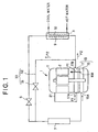
- Fig. 1 shows a heat pump apparatus using a two-stage compression type rotary compressor.
- Reference numeral 1 represents a compressor.
- a gas cooler high-pressure side heat exchanger
- a pressure reducing device expansion valve
- evaporator low-pressure side heat exchanger
- the refrigerating cycle uses CO 2 refrigerant.
- the CO 2 refrigerant has an ozone depletion coefficient of zero and a global warming potential of 1. Therefore, it has a low load on the environment, has no toxicity and no flammability, and is safe and low in price.
- CO 2 refrigerant is used, a transcritical cycle in which the high-pressure side of the refrigerating cycle is transformed into a supercritical state is established, and thus it is expected that a high coefficient of performance is achieved in a heating processing having a large water-temperature rise-up range as in the case of hot water supply in a heat pump type hot water supply apparatus.
- the refrigerant must be compressed to a high pressure, and thus an internal intermediate pressure two-stage compression type compressor is used as the compressor 1.
- the internal intermediate pressure two-stage compression type compressor 1 has an electric motor portion 2 and a compressing portion 13 driven by the electric motor portion 2, which are mounted in a shell case 11.
- the compressing poriton13 has a two-stage compressing structure, and it comprises a first-stage compressing portion 15 and a second-stage compressing portion 17.
- Refrigerant sucked from the suction port 15A of the first-stage compressing portion 15 is compressed to an intermediate pressure P1 in the compressing portion 15, and then all the refrigerant thus compressed is temporarily discharged from the discharge port 15B into the shell case 11.
- the refrigerant After passing through the shell case 11, the refrigerant is passed through a pipe path 21, led to the suction port 17A of the second-stage compressing portion 17, compressed to a high pressure P2 in the second-stage compressing portion 17, and then discharged from the discharge port 17B.
- the gas cooler 3 comprises a refrigerant coil 9 through which CO 2 refrigerant flows, and a water coil 10 through which water flows, and the water coil 10 is connected through a water pipe to a hot water reservoir tank (not shown).
- a circulating pump omitted from the illustration is connected to the water pipe, and water in the hot water reservoir tank is circulated in the gas cooler 3 by driving the circulating pump. The water is heated in the gas cooler 3, and then stocked in the hot water reservoir tank.
- the heat pump apparatus is disposed as a heat pump unit outdoors, and thus it is necessary to remove frost attached to the evaporator 7.
- a hot gas defrosting circuit 33 containing a defrosting electromagnetic valve 31 and a bypass pipe 32 is equipped to lead the high-pressure P2 refrigerant of the second stage 17 of the compressor 1 to the evaporator 7 with bypassing the gas cooler 3 and the pressure reducing device 5.
- the normally-closed defrosting electromagnetic valve 31 equipped in the bypass pipe 32 is opened.
- the high-pressure refrigerant of the compressor 1 is fed to the evaporator 7 to heat the evaporator 7, thereby removing frost attached to the evaporator.
- This embodiment can perform the efficient defrosting operation when the internal intermediate pressure two-stage compression type compressor 1 is used.
- the high-pressure P2 refrigerant of the compressor 1 is directly supplied to the evaporator 7, so that there may occur a case where the inner pressure of the shell case 11 is higher than the discharge pressure P2 and thus the refrigerant lies up in the shell case 11, or a case where no vane back pressure of the compressor 1 is applied and thus so-called vane skipping occurs to induce abnormal sounds.
- the reason why the inner pressure of the shell case 11 is increased resides in that the excluded volume of the first stage of the compressor 1 is larger than the excluded volume of the second stage, or the resistance balance of the refrigerant circulating path is lost. If the refrigerant lies up in the shell case 11, the refrigerant circulation amount is short and thus sufficient defrosting cannot be performed.
- Fig. 2 shows another embodiment.
- this embodiment is equipped with a hot gas defrosting circuit 133 containing a defrosting electromagnetic valve 131 and a bypass pipe 132 to lead the intermediate pressure P1 refrigerant of the first stage 15 of the compressor 1 to the evaporator 7 with bypassing the gas cooler 3 and the pressure reducing device 5.
- a normally-closed defrosting electromagnetic valve 131 equipped in the bypass pipe 132 is opened.
- the mixing ratio of refrigerating-machine oil contained in the refrigerant of the intermediate pressure P1 discharged from the first stage and the mixing ratio of refrigerating-machine oil contained in the refrigerant of the high-pressure P2 discharged from the second stage are different from each other. That is, the mixing ratio of the oil contained in the refrigerant of the intermediate pressure P1 is generally smaller than the mixing ratio of the oil contained in the refrigerant of the high pressure P2.
- the discharge amount of the oil in the defrosting operation is reduced and the residual oil amount in the shell case can be sufficiently secured as compared with the embodiment shown in Fig. 1, so that the durability of the compressor 1 can be enhanced.
- Fig. 3 shows another embodiment.
- this embodiment is further provided with a hot gas defrosting circuit 233 containing a defrosting intermediate electromagnetic valve 231 and a bypass pipe 232 for leading the high-pressure P2 refrigerant of the second stage 17 of the compressor 1 to the evaporator 7 with bypassing the gas cooler 3 and the pressure reducing device 5.
- a hot gas defrosting circuit 233 containing a defrosting intermediate electromagnetic valve 231 and a bypass pipe 232 for leading the high-pressure P2 refrigerant of the second stage 17 of the compressor 1 to the evaporator 7 with bypassing the gas cooler 3 and the pressure reducing device 5.
- both the normally-closed defrosting electromagnetic valves 131, 231 are opened.
- This embodiment can achieve the same effect as the embodiment shown in Fig. 2.
- the inside of the shell case 11 of the compressor 1 which is set to the inner intermediate pressure is vacuum-evacuated, and then refrigerant is sealingly filled in the refrigerating cycle.
- the vacuum-evacuation is carried out from any one or both of the suction port of the first stage and the discharge port of the second stage, however, in any case, the working is difficult.
- the defrosting intermediate electromagnetic valve 231 is provided in the bypass 232, and thus the vacuum-evacuation can be carried out from this site. Accordingly, the vacuum-evacuation of the inside of the shell case 11 is easily performed, the residual amount of impurity gas in the refrigerating cycle is reduced, deterioration of durability of the refrigerating-machine oil circulated in the refrigerating cycle is suppressed, and the durability of the compressor 1 can be enhanced.
- Fig. 4 shows another embodiment.
- This embodiment has substantially the same construction as the embodiment shown in Fig. 3, and differs in the construction that not all, but a part of the refrigerant of the first stage of the compressor 1 is supplied into the shell case 11, and the remaining refrigerant is directly supplied from the discharge port 15B of the first stage through a pipe path 51 to the suction port 17A of the second stage.
- This construction can provided substantially the same effect as the embodiment as described above.
- the compressor of this embodiment may be applied to the defrosting circuit shown in Fig. 1, the defrosting circuit shown in Fig. 2, etc.
- the present invention is suitably applied to a heat pump apparatus which can perform an efficient defrosting operation when an internal intermediate pressure two-stage compression type compressor is used.
Landscapes
- Engineering & Computer Science (AREA)
- Physics & Mathematics (AREA)
- Mechanical Engineering (AREA)
- Thermal Sciences (AREA)
- General Engineering & Computer Science (AREA)
- Chemical & Material Sciences (AREA)
- Chemical Kinetics & Catalysis (AREA)
- Heat-Pump Type And Storage Water Heaters (AREA)
- Defrosting Systems (AREA)
Applications Claiming Priority (3)
| Application Number | Priority Date | Filing Date | Title |
|---|---|---|---|
| JP2001200412 | 2001-07-02 | ||
| JP2001200412 | 2001-07-02 | ||
| PCT/JP2002/006685 WO2003004948A1 (en) | 2001-07-02 | 2002-07-02 | Heat pump device |
Publications (3)
| Publication Number | Publication Date |
|---|---|
| EP1403600A1 true EP1403600A1 (de) | 2004-03-31 |
| EP1403600A4 EP1403600A4 (de) | 2006-06-07 |
| EP1403600B1 EP1403600B1 (de) | 2008-07-09 |
Family
ID=19037538
Family Applications (1)
| Application Number | Title | Priority Date | Filing Date |
|---|---|---|---|
| EP02743779A Expired - Fee Related EP1403600B1 (de) | 2001-07-02 | 2002-07-02 | Wärmepumpenvorrichtung |
Country Status (7)
| Country | Link |
|---|---|
| US (1) | US6880352B2 (de) |
| EP (1) | EP1403600B1 (de) |
| JP (1) | JPWO2003004948A1 (de) |
| KR (1) | KR20030028831A (de) |
| CN (1) | CN1228594C (de) |
| DE (1) | DE60227520D1 (de) |
| WO (1) | WO2003004948A1 (de) |
Cited By (3)
| Publication number | Priority date | Publication date | Assignee | Title |
|---|---|---|---|---|
| US6511017B2 (en) | 1999-03-01 | 2003-01-28 | Natural Colour Kari Kirjavainen Oy | Method of steering aircraft, and aircraft |
| EP1703130A2 (de) | 2001-09-27 | 2006-09-20 | Sanyo Electric Co., Ltd. | Flügelzellenverdichter und Enteisungsvorrichtung |
| EP1972870A3 (de) * | 2002-08-30 | 2008-12-10 | Sanyo Electric Co., Ltd. | Kältemittelkreislaufvorrichtung und Verdichter damit |
Families Citing this family (15)
| Publication number | Priority date | Publication date | Assignee | Title |
|---|---|---|---|---|
| JP2005003239A (ja) * | 2003-06-10 | 2005-01-06 | Sanyo Electric Co Ltd | 冷媒サイクル装置 |
| WO2006103815A1 (ja) * | 2005-03-28 | 2006-10-05 | Toshiba Carrier Corporation | 給湯機 |
| WO2007086871A1 (en) * | 2006-01-27 | 2007-08-02 | Carrier Corporation | Refrigerant system unloading by-pass into evaporator inlet |
| JP4982119B2 (ja) * | 2006-06-29 | 2012-07-25 | 株式会社東芝 | 回転電機 |
| KR20080020771A (ko) * | 2006-09-01 | 2008-03-06 | 엘지전자 주식회사 | 수냉식 공기조화기 |
| JP5140398B2 (ja) * | 2007-11-30 | 2013-02-06 | 三洋電機株式会社 | 冷凍装置 |
| WO2011054397A1 (en) * | 2009-11-06 | 2011-05-12 | Carrier Corporation | Refrigerating circuit and method for selectively defrosting cold consumer units of a refrigerating circuit |
| JP2011133208A (ja) * | 2009-12-25 | 2011-07-07 | Sanyo Electric Co Ltd | 冷凍装置 |
| US10184688B2 (en) | 2011-12-28 | 2019-01-22 | Desert Aire Corp. | Air conditioning apparatus for efficient supply air temperature control |
| CN105008822B (zh) * | 2013-02-20 | 2017-05-17 | 松下知识产权经营株式会社 | 废热利用热泵系统和热机驱动式蒸气压缩式热泵系统 |
| WO2014192140A1 (ja) * | 2013-05-31 | 2014-12-04 | 三菱電機株式会社 | 空気調和装置 |
| CN103673391B (zh) * | 2013-12-09 | 2016-05-11 | 江苏苏净集团有限公司 | 二氧化碳热泵系统及其控制方法 |
| CA2879702C (en) | 2014-01-22 | 2016-11-08 | Jeremy Hogan | Heat pump temperature control |
| US10267539B2 (en) | 2014-02-17 | 2019-04-23 | Carrier Corporation | Hot gas bypass for two-stage compressor |
| CN105962005B (zh) * | 2016-05-09 | 2019-12-27 | 顺德职业技术学院 | 双级压缩式热泵真空冷冻干燥组合设备节能控制方法 |
Citations (3)
| Publication number | Priority date | Publication date | Assignee | Title |
|---|---|---|---|---|
| US3869874A (en) * | 1974-01-02 | 1975-03-11 | Borg Warner | Refrigeration apparatus with defrosting system |
| JPS54146048A (en) * | 1978-05-08 | 1979-11-14 | Mitsubishi Electric Corp | Double-step compression type freezer |
| JPH03170758A (ja) * | 1989-11-30 | 1991-07-24 | Mitsubishi Electric Corp | 空気調和装置 |
Family Cites Families (17)
| Publication number | Priority date | Publication date | Assignee | Title |
|---|---|---|---|---|
| JPS5524527Y2 (de) * | 1976-06-09 | 1980-06-12 | ||
| JPS5752592Y2 (de) * | 1978-07-07 | 1982-11-15 | ||
| JPS5510961A (en) | 1978-07-11 | 1980-01-25 | Mitsubishi Electric Corp | Particle accelerator for medical treatment |
| JPS6453868A (en) | 1987-08-25 | 1989-03-01 | Fuji Photo Film Co Ltd | Printing method |
| JPS6453868U (de) * | 1987-09-29 | 1989-04-03 | ||
| JPH028660A (ja) | 1988-06-27 | 1990-01-12 | Mitsubishi Electric Corp | 冷凍機 |
| JPH0213765A (ja) * | 1988-06-30 | 1990-01-18 | Toshiba Corp | 冷凍サイクル装置 |
| JPH07133973A (ja) * | 1993-11-10 | 1995-05-23 | Mitsubishi Heavy Ind Ltd | 冷凍装置 |
| JP3182598B2 (ja) * | 1994-02-04 | 2001-07-03 | 株式会社日立製作所 | 冷凍装置 |
| US5570585A (en) * | 1994-10-03 | 1996-11-05 | Vaynberg; Mikhail | Universal cooling system automatically configured to operate in compound or single compressor mode |
| JPH0933144A (ja) * | 1995-07-17 | 1997-02-07 | Sanyo Electric Co Ltd | 冷凍回路の真空引き方法及びその装置 |
| WO1997027437A1 (de) * | 1996-01-26 | 1997-07-31 | Konvekta Ag | Kompressionskälteanlage |
| JP3458058B2 (ja) * | 1998-04-13 | 2003-10-20 | 株式会社神戸製鋼所 | 冷凍装置 |
| US6112547A (en) * | 1998-07-10 | 2000-09-05 | Spauschus Associates, Inc. | Reduced pressure carbon dioxide-based refrigeration system |
| JP2000171108A (ja) * | 1998-12-03 | 2000-06-23 | Sanyo Electric Co Ltd | ロータリ圧縮機及びそれを用いた冷凍回路 |
| JP4441965B2 (ja) | 1999-06-11 | 2010-03-31 | ダイキン工業株式会社 | 空気調和装置 |
| JP2002106963A (ja) * | 2000-09-29 | 2002-04-10 | Sanyo Electric Co Ltd | ヒートポンプ給湯機 |
-
2002
- 2002-07-02 JP JP2003510879A patent/JPWO2003004948A1/ja active Pending
- 2002-07-02 CN CNB028026187A patent/CN1228594C/zh not_active Expired - Fee Related
- 2002-07-02 WO PCT/JP2002/006685 patent/WO2003004948A1/ja active IP Right Grant
- 2002-07-02 KR KR10-2003-7002979A patent/KR20030028831A/ko not_active Application Discontinuation
- 2002-07-02 EP EP02743779A patent/EP1403600B1/de not_active Expired - Fee Related
- 2002-07-02 US US10/380,161 patent/US6880352B2/en not_active Expired - Fee Related
- 2002-07-02 DE DE60227520T patent/DE60227520D1/de not_active Expired - Lifetime
Patent Citations (3)
| Publication number | Priority date | Publication date | Assignee | Title |
|---|---|---|---|---|
| US3869874A (en) * | 1974-01-02 | 1975-03-11 | Borg Warner | Refrigeration apparatus with defrosting system |
| JPS54146048A (en) * | 1978-05-08 | 1979-11-14 | Mitsubishi Electric Corp | Double-step compression type freezer |
| JPH03170758A (ja) * | 1989-11-30 | 1991-07-24 | Mitsubishi Electric Corp | 空気調和装置 |
Non-Patent Citations (3)
| Title |
|---|
| PATENT ABSTRACTS OF JAPAN vol. 004, no. 009 (M-089), 23 January 1980 (1980-01-23) -& JP 54 146048 A (MITSUBISHI ELECTRIC CORP), 14 November 1979 (1979-11-14) * |
| PATENT ABSTRACTS OF JAPAN vol. 015, no. 411 (M-1170), 21 October 1991 (1991-10-21) -& JP 03 170758 A (MITSUBISHI ELECTRIC CORP), 24 July 1991 (1991-07-24) * |
| See also references of WO03004948A1 * |
Cited By (4)
| Publication number | Priority date | Publication date | Assignee | Title |
|---|---|---|---|---|
| US6511017B2 (en) | 1999-03-01 | 2003-01-28 | Natural Colour Kari Kirjavainen Oy | Method of steering aircraft, and aircraft |
| EP1703130A2 (de) | 2001-09-27 | 2006-09-20 | Sanyo Electric Co., Ltd. | Flügelzellenverdichter und Enteisungsvorrichtung |
| EP1703130A3 (de) * | 2001-09-27 | 2007-10-03 | Sanyo Electric Co., Ltd. | Flügelzellenverdichter und Enteisungsvorrichtung |
| EP1972870A3 (de) * | 2002-08-30 | 2008-12-10 | Sanyo Electric Co., Ltd. | Kältemittelkreislaufvorrichtung und Verdichter damit |
Also Published As
| Publication number | Publication date |
|---|---|
| EP1403600A4 (de) | 2006-06-07 |
| WO2003004948A1 (en) | 2003-01-16 |
| CN1228594C (zh) | 2005-11-23 |
| CN1464964A (zh) | 2003-12-31 |
| EP1403600B1 (de) | 2008-07-09 |
| KR20030028831A (ko) | 2003-04-10 |
| DE60227520D1 (de) | 2008-08-21 |
| US20030188544A1 (en) | 2003-10-09 |
| JPWO2003004948A1 (ja) | 2004-10-28 |
| US6880352B2 (en) | 2005-04-19 |
Similar Documents
| Publication | Publication Date | Title |
|---|---|---|
| US6880352B2 (en) | Heat pump device | |
| KR101201062B1 (ko) | 냉동 장치 | |
| JP4658347B2 (ja) | 超臨界蒸気圧縮冷凍サイクル | |
| EP2381180B1 (de) | Warmwasserversorgungsvorrichtung nach Art einer Wärmepumpe | |
| CN105849475B (zh) | 复合式空气调节器 | |
| EP2230475B1 (de) | Kühlvorrichtung | |
| KR101214310B1 (ko) | 냉동 장치 | |
| EP2162686A1 (de) | Kältemittelsystem mit kaskadenkreisläufen und leistungsverbesserungsmerkmalen | |
| US7024879B2 (en) | Refrigerator | |
| JP2009133585A (ja) | 冷凍装置 | |
| US9249997B2 (en) | Refrigeration apparatus having an intercooler disposed between first and second stages of a compression mechanism and an intercooler bypass tube to bypass the intercooler | |
| US8327661B2 (en) | Refrigeration apparatus | |
| JP2010112579A (ja) | 冷凍装置 | |
| CN101910758A (zh) | 压力释放装置在高压致冷系统中的固定 | |
| CN110494702B (zh) | 制冷循环装置 | |
| JP6765086B2 (ja) | 冷凍装置 | |
| WO2019186647A1 (ja) | 冷凍装置 | |
| JP2003013860A (ja) | 二段圧縮型圧縮機およびそれを用いた冷凍装置 | |
| JP3631244B2 (ja) | ヒートポンプ装置 | |
| JP3594570B2 (ja) | 二段圧縮型圧縮機およびそれを用いた冷凍装置 | |
| JP3711070B2 (ja) | ヒートポンプ給湯機 | |
| JP2007147228A (ja) | 冷凍装置 | |
| JP3815611B2 (ja) | ヒートポンプ給湯機 | |
| EP4145061A1 (de) | Kühlschrank | |
| JP5197255B2 (ja) | アンモニア冷凍装置 |
Legal Events
| Date | Code | Title | Description |
|---|---|---|---|
| PUAI | Public reference made under article 153(3) epc to a published international application that has entered the european phase |
Free format text: ORIGINAL CODE: 0009012 |
|
| 17P | Request for examination filed |
Effective date: 20040114 |
|
| AK | Designated contracting states |
Kind code of ref document: A1 Designated state(s): AT BE BG CH CY CZ DE DK EE ES FI FR GB GR IE IT LI LU MC NL PT SE SK TR |
|
| RIN1 | Information on inventor provided before grant (corrected) |
Inventor name: MUKAIYAMA, HIROSHI Inventor name: YAMASAKI, HARUHISA |
|
| A4 | Supplementary search report drawn up and despatched |
Effective date: 20060511 |
|
| 17Q | First examination report despatched |
Effective date: 20061027 |
|
| GRAP | Despatch of communication of intention to grant a patent |
Free format text: ORIGINAL CODE: EPIDOSNIGR1 |
|
| GRAS | Grant fee paid |
Free format text: ORIGINAL CODE: EPIDOSNIGR3 |
|
| GRAA | (expected) grant |
Free format text: ORIGINAL CODE: 0009210 |
|
| AK | Designated contracting states |
Kind code of ref document: B1 Designated state(s): DE FR GB IT |
|
| REG | Reference to a national code |
Ref country code: GB Ref legal event code: FG4D |
|
| REF | Corresponds to: |
Ref document number: 60227520 Country of ref document: DE Date of ref document: 20080821 Kind code of ref document: P |
|
| PLBE | No opposition filed within time limit |
Free format text: ORIGINAL CODE: 0009261 |
|
| STAA | Information on the status of an ep patent application or granted ep patent |
Free format text: STATUS: NO OPPOSITION FILED WITHIN TIME LIMIT |
|
| 26N | No opposition filed |
Effective date: 20090414 |
|
| PGFP | Annual fee paid to national office [announced via postgrant information from national office to epo] |
Ref country code: DE Payment date: 20140625 Year of fee payment: 13 |
|
| PGFP | Annual fee paid to national office [announced via postgrant information from national office to epo] |
Ref country code: GB Payment date: 20140702 Year of fee payment: 13 Ref country code: FR Payment date: 20140708 Year of fee payment: 13 |
|
| PGFP | Annual fee paid to national office [announced via postgrant information from national office to epo] |
Ref country code: IT Payment date: 20140714 Year of fee payment: 13 |
|
| REG | Reference to a national code |
Ref country code: DE Ref legal event code: R082 Ref document number: 60227520 Country of ref document: DE |
|
| REG | Reference to a national code |
Ref country code: DE Ref legal event code: R119 Ref document number: 60227520 Country of ref document: DE |
|
| GBPC | Gb: european patent ceased through non-payment of renewal fee |
Effective date: 20150702 |
|
| PG25 | Lapsed in a contracting state [announced via postgrant information from national office to epo] |
Ref country code: IT Free format text: LAPSE BECAUSE OF NON-PAYMENT OF DUE FEES Effective date: 20150702 Ref country code: GB Free format text: LAPSE BECAUSE OF NON-PAYMENT OF DUE FEES Effective date: 20150702 Ref country code: DE Free format text: LAPSE BECAUSE OF NON-PAYMENT OF DUE FEES Effective date: 20160202 |
|
| REG | Reference to a national code |
Ref country code: FR Ref legal event code: ST Effective date: 20160331 |
|
| PG25 | Lapsed in a contracting state [announced via postgrant information from national office to epo] |
Ref country code: FR Free format text: LAPSE BECAUSE OF NON-PAYMENT OF DUE FEES Effective date: 20150731 |