EP1403566A2 - Methode und Vorrichtung zur Hydraulikdrucksteuerung eines automatischen Getriebes mit einem Überbrückungsventil - Google Patents
Methode und Vorrichtung zur Hydraulikdrucksteuerung eines automatischen Getriebes mit einem Überbrückungsventil Download PDFInfo
- Publication number
- EP1403566A2 EP1403566A2 EP03022198A EP03022198A EP1403566A2 EP 1403566 A2 EP1403566 A2 EP 1403566A2 EP 03022198 A EP03022198 A EP 03022198A EP 03022198 A EP03022198 A EP 03022198A EP 1403566 A2 EP1403566 A2 EP 1403566A2
- Authority
- EP
- European Patent Office
- Prior art keywords
- lockup
- pressure
- lockup clutch
- signal pressure
- control valve
- Prior art date
- Legal status (The legal status is an assumption and is not a legal conclusion. Google has not performed a legal analysis and makes no representation as to the accuracy of the status listed.)
- Withdrawn
Links
Images



Classifications
-
- F—MECHANICAL ENGINEERING; LIGHTING; HEATING; WEAPONS; BLASTING
- F16—ENGINEERING ELEMENTS AND UNITS; GENERAL MEASURES FOR PRODUCING AND MAINTAINING EFFECTIVE FUNCTIONING OF MACHINES OR INSTALLATIONS; THERMAL INSULATION IN GENERAL
- F16H—GEARING
- F16H61/00—Control functions within control units of change-speed- or reversing-gearings for conveying rotary motion ; Control of exclusively fluid gearing, friction gearing, gearings with endless flexible members or other particular types of gearing
- F16H61/14—Control of torque converter lock-up clutches
-
- F—MECHANICAL ENGINEERING; LIGHTING; HEATING; WEAPONS; BLASTING
- F16—ENGINEERING ELEMENTS AND UNITS; GENERAL MEASURES FOR PRODUCING AND MAINTAINING EFFECTIVE FUNCTIONING OF MACHINES OR INSTALLATIONS; THERMAL INSULATION IN GENERAL
- F16H—GEARING
- F16H61/00—Control functions within control units of change-speed- or reversing-gearings for conveying rotary motion ; Control of exclusively fluid gearing, friction gearing, gearings with endless flexible members or other particular types of gearing
- F16H61/14—Control of torque converter lock-up clutches
- F16H61/143—Control of torque converter lock-up clutches using electric control means
-
- F—MECHANICAL ENGINEERING; LIGHTING; HEATING; WEAPONS; BLASTING
- F16—ENGINEERING ELEMENTS AND UNITS; GENERAL MEASURES FOR PRODUCING AND MAINTAINING EFFECTIVE FUNCTIONING OF MACHINES OR INSTALLATIONS; THERMAL INSULATION IN GENERAL
- F16H—GEARING
- F16H59/00—Control inputs to control units of change-speed- or reversing-gearings for conveying rotary motion
- F16H59/14—Inputs being a function of torque or torque demand
- F16H2059/147—Transmission input torque, e.g. measured or estimated engine torque
-
- F—MECHANICAL ENGINEERING; LIGHTING; HEATING; WEAPONS; BLASTING
- F16—ENGINEERING ELEMENTS AND UNITS; GENERAL MEASURES FOR PRODUCING AND MAINTAINING EFFECTIVE FUNCTIONING OF MACHINES OR INSTALLATIONS; THERMAL INSULATION IN GENERAL
- F16H—GEARING
- F16H61/00—Control functions within control units of change-speed- or reversing-gearings for conveying rotary motion ; Control of exclusively fluid gearing, friction gearing, gearings with endless flexible members or other particular types of gearing
- F16H61/02—Control functions within control units of change-speed- or reversing-gearings for conveying rotary motion ; Control of exclusively fluid gearing, friction gearing, gearings with endless flexible members or other particular types of gearing characterised by the signals used
- F16H61/0202—Control functions within control units of change-speed- or reversing-gearings for conveying rotary motion ; Control of exclusively fluid gearing, friction gearing, gearings with endless flexible members or other particular types of gearing characterised by the signals used the signals being electric
- F16H61/0251—Elements specially adapted for electric control units, e.g. valves for converting electrical signals to fluid signals
- F16H2061/0253—Details of electro hydraulic valves, e.g. lands, ports, spools or springs
-
- F—MECHANICAL ENGINEERING; LIGHTING; HEATING; WEAPONS; BLASTING
- F16—ENGINEERING ELEMENTS AND UNITS; GENERAL MEASURES FOR PRODUCING AND MAINTAINING EFFECTIVE FUNCTIONING OF MACHINES OR INSTALLATIONS; THERMAL INSULATION IN GENERAL
- F16H—GEARING
- F16H61/00—Control functions within control units of change-speed- or reversing-gearings for conveying rotary motion ; Control of exclusively fluid gearing, friction gearing, gearings with endless flexible members or other particular types of gearing
- F16H61/66—Control functions within control units of change-speed- or reversing-gearings for conveying rotary motion ; Control of exclusively fluid gearing, friction gearing, gearings with endless flexible members or other particular types of gearing specially adapted for continuously variable gearings
- F16H2061/6604—Special control features generally applicable to continuously variable gearings
- F16H2061/6608—Control of clutches, or brakes for forward-reverse shift
-
- F—MECHANICAL ENGINEERING; LIGHTING; HEATING; WEAPONS; BLASTING
- F16—ENGINEERING ELEMENTS AND UNITS; GENERAL MEASURES FOR PRODUCING AND MAINTAINING EFFECTIVE FUNCTIONING OF MACHINES OR INSTALLATIONS; THERMAL INSULATION IN GENERAL
- F16H—GEARING
- F16H59/00—Control inputs to control units of change-speed- or reversing-gearings for conveying rotary motion
- F16H59/14—Inputs being a function of torque or torque demand
Definitions
- the present invention relates to a system for controlling the hydraulic pressure of an automatic transmission including a lockup control valve.
- a hydraulic circuit for a V-belt type continuously variable transmission comprises a lockup control valve for engaging a lockup clutch of a torque converter for direct coupling between an engine and a CVT.
- the lockup control valve bifurcates the hydraulic pressure drained from a clutch regulating valve into two pressures of the apply side and release side of the torque converter in accordance with a signal output from a lockup solenoid.
- the lockup control valve carries out engagement and disengagement of the lockup clutch.
- the lockup solenoid includes a linear solenoid valve which changes a constant pilot pressure supplied from a pilot valve in accordance with a control signal output from a CVT control unit to provide it, as a signal pressure, to the lockup control valve.
- the linear solenoid valve has the advantage of higher responsivity than a duty control valve.
- the lockup solenoid receives the pilot pressure through an input port to provide it, as a lockup-solenoid source pressure, through an output port.
- the lockup solenoid changes the volume defined between a valve element arranged at an end of a plunger and a bearing surface formed on a valve chest by a balance between a biasing force of the solenoid and the pilot pressure, thus changing the pilot pressure to a desired pressure.
- an indicated value of the differential pressure of the lockup solenoid after engagement of the lockup clutch is set at a maximum value at all times to maximize an engagement capacity of the torque converter.
- a spool of the lockup control valve is in the fully biased state at all times to increase the load rigidity of a particular hydraulic passage as viewed from the lockup solenoid.
- a solution for absorbing surging of the pilot pressure lies in interposing an accumulator between the pilot valve and the lockup solenoid.
- this solution involves an increase in the number of parts, leading to increase in manufacturing cost and degradation in the vehicle mountability.
- Another solution lies in setting the source pressure of the lockup control valve, i.e. the discharge capacity of an oil pump, at a fully high value.
- this solution involves provision of the source pressure of the lockup control valve greater than the differential pressure required for a maximum engagement capacity of the lockup clutch, increasing a load to the engine for driving the oil pump, causing degradation of fuel consumption.
- an object of the present invention to provide a system for controlling the hydraulic pressure of an automatic transmission including a lockup control valve, which allows achievement of the control stability of the lockup clutch at all times.
- the present invention provides generally a system for controlling a hydraulic pressure of an automatic transmission, which comprises: a torque converter comprising a lockup clutch, the lockup clutch carrying out direct coupling between an engine and the transmission; a lockup solenoid valve which provides a signal pressure for controlling engagement of the lockup clutch; a lockup control valve which provides an engagement pressure to the lockup clutch in accordance with the signal pressure; and a control unit which controls the lockup solenoid valve, the control unit being programmed to: determine a torque provided to the torque converter; and control the signal pressure in accordance with the torque.
- FIG. 1 is a block diagram showing a first embodiment of a hydraulic control system for an automatic transmission including a lockup control valve according to the present invention
- FIG. 2 is a diagram showing a hydraulic circuit for the automatic transmission
- FIG. 3 is a flow chart illustrating operation of the first embodiment
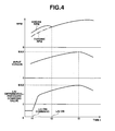
- FIG. 4 is a time chart showing operation of the first embodiment
- FIG. 5A is a schematic sectional view showing a second embodiment of the present invention.
- FIG. 5B is a view similar to FIG. 5A, showing the second embodiment.
- the hydraulic control system comprises a torque converter 1, a lockup clutch 3, a V-belt type CVT 3, a primary rpm sensor 4, a secondary rpm sensor 5, a hydraulic control valve unit 6, an oil pump 8 driven by an engine, not shown, a CVT control unit (CVTCU) 9, a throttle-opening sensor 10, and an engine control unit (ECU) 11.
- a torque converter 1 a lockup clutch 3
- a V-belt type CVT 3 3
- a primary rpm sensor 4 a secondary rpm sensor 5
- a hydraulic control valve unit 6 an oil pump 8 driven by an engine, not shown
- CVT control unit (CVTCU) 9 a throttle-opening sensor 10
- ECU engine control unit
- the engine includes an output shaft 12 to which the torque converter or rotation transfer mechanism1 is coupled, and to which a lockup clutch 2 is provided for direct coupling between the engine and the CVT 3.
- the torque converter 1 has an output side coupled to a ring gear 21 of a forward/reverse switching mechanism 20.
- the forward/reverse switching mechanism 20 comprises a planetary-gear set comprising a ring gear 21 coupled to the engine output shaft 12, a pinion carrier 22, a sun gear 23 coupled to a transmission input shaft 13.
- a reverse brake 24 for fixing the pinion carrier 22 to a transmission casing
- a forward clutch 25 for integrally coupling the transmission input shaft 13 to the pinion carrier 22.
- a primary pulley 30a of the CVT 3 is arranged at an end of the transmission input shaft 13.
- the CVT 3 comprises primary pulley 30a, a secondary pulley 30b, and a belt 34 for transferring torque of the primary pulley 30a to the secondary pulley 30b.
- the primary pulley 30a comprises a stationary conical plate 31 rotating together with the transmission input shaft 13, and a movable conical plate 32 disposed opposite to the stationary conical plate 31 to form a V-shaped pulley groove and being axially movable in accordance with the hydraulic pressure acting on a primary-pulley cylinder chamber 33.
- the secondary pulley 30b is arranged on a driven shaft 38, and comprises a stationary conical plate 35 rotating together with the driven shaft 38 and a movable conical plate 36 disposed opposite to the stationary conical plate 35 to form a V-shaped pulley groove and being axially movable in accordance with the hydraulic pressure acting on a secondary-pulley cylinder chamber 37.
- a drive gear is fixed to the drive shaft 38 so as to drive a drive shaft extending to wheels, not shown, through a pinion, final gear, differential gear provided to an idler shaft.
- Torque of the engine output shaft 12 is transferred to the CVT 3 through the torque converter 1 and the forward/reverse switching mechanism 20.
- Torque of the transmission input shaft 13 is transferred to the differential gear through the primary pulley 30a, belt 34, secondary pulley 30b, driven shaft 38, drive gear, idler gear, idler shaft, pinion, and final gear.
- the CVTCU 9 receives a throttle-opening signal from the throttle-opening sensor 10, a primary-rpm signal from the primary rpm sensor 4, a secondary-rpm signal from the secondary rpm sensor 5, an engine-torque signal from the ECU 11, and a cramp pressure from a pulley cramp-pressure sensor 14.
- a control signal is calculated in accordance with the input signals to provide it to the hydraulic control valve unit 6.
- the hydraulic control valve unit 6 receives a control signal from the CVTCU 9 to provide the control pressures to the primary-pulley cylinder and secondary-pulley cylinder chambers 33, 37, thus carrying out shift control.
- the hydraulic circuit comprises a pressure regulating valve 40 for regulating the discharge pressure of the oil pump 8 supplied through a hydraulic passage 41 to serve as the line pressure or pulley cramp pressure.
- the hydraulic passage 41 communicates with a hydraulic passage 42.
- the hydraulic passage 42 is a pulley-cramp-pressure supply passage which supplies the pulley cramp pressure for cramping the belt 34 to the primary-pulley cylinder and secondary-pulley cylinder chambers 33, 37 of the CVT 3.
- a hydraulic passage 43 communicating with the hydraulic passage 42 serves to supply the source pressure of a pilot valve 50.
- the hydraulic pressure drained from the pressure regulating valve 40 is supplied to a clutch regulating valve 60 through a hydraulic passage 46.
- the hydraulic passage 46 communicates with a hydraulic passage 44 communicating with the hydraulic passage 42 and having an orifice 45.
- the clutch regulating valve 60 regulates the hydraulic pressures within hydraulic passages 46, 61.
- the hydraulic pressure within the hydraulic passage 61 is supplied to a select switching valve 80 and a select control valve 90.
- the pilot valve 50 serves to set a constant supply pressure to a lockup solenoid 71 and a select switching solenoid 70 through a hydraulic passage 51.
- the output pressure of the select switching solenoid 70 is supplied to the select switching valve for operation control thereof.
- the output pressure of the lockup solenoid 71 is supplied to the select switching valve 80.
- the select switching valve 80 is actuated by the select switching solenoid 70.
- a hydraulic passage 72 for supplying the signal pressure of the lockup solenoid 71, hydraulic passage 61 having hydraulic pressure regulated by the clutch regulating valve 60, and a hydraulic passage 93 having hydraulic pressure regulated by the select control valve 90.
- a hydraulic passage 81 for supplying the forward-clutch pressure to a manual valve, not shown, a hydraulic passage 82 for supplying the hydraulic pressure to a lockup control valve 100, a hydraulic passage 83 for supplying the hydraulic pressure for actuating a spool 92 of the select control valve 90, and a hydraulic passage 84 for draining the hydraulic pressure from the select switching valve 80.
- a hydraulic passage 62 having hydraulic pressure regulated by the clutch regulating valve 60 and hydraulic passage 83 for supplying the signal pressure of the lockup solenoid 71.
- the select control valve 90 controls communication between the hydraulic passages 62, 93, thus regulating the hydraulic pressure.
- the signal pressure of the lockup solenoid 71 operates as the signal pressure of the select control valve 90 through the select switching valve 80. And the hydraulic pressure regulated by the select control valve 90 is supplied to the manual valve.
- a hydraulic passage 64 having hydraulic pressure drained from the clutch regulating valve 60 and regulated by a torque-converter regulating valve 110 and a hydraulic passage 105 having hydraulic pressure drained from the torque-converter regulating valve 110.
- hydraulic passages 102, 103 for supplying the release pressure to the torque converter 1, hydraulic passages 106, 108 for supplying the apply pressure to the torque converter 1, and a hydraulic passage 107 for draining the hydraulic passage from the lockup control valve 100 to an oil cooler, not shown.
- the torque-converter regulating valve 110 regulates the hydraulic pressure drained from the clutch regulating valve 60 to supply it to the lockup control valve 100 through the hydraulic passage 64.
- a step S201 it is determined whether or not a command for engaging the lockup clutch 2 is provided. If it is determined that the command is provided, control proceeds to a step S202, whereas if it is determined that the command is not provided, control comes to an end.
- step S202 it is read engine torque derived from the ECU 11, i.e. input torque.
- a differential-pressure command value for the lockup solenoid 71 is determined in accordance with input torque.
- a control signal is provided to the lockup solenoid 71.
- step S201 the vehicle velocity reaches a predetermined value, so that a command for engaging the lockup clutch 2 is provided to the lockup solenoid 71.
- control is carried out along flow of step S201 ⁇ step S202 ⁇ step S203 ⁇ step S204 in FIG. 3.
- the differential-pressure command value is reduced. At that time, as engine rotation is higher, the signal pressure of the differential-pressure command value surges. However, since the differential-pressure command value is smaller than the maximum value, a spool of the lockup control valve 100 absorbs surging of the signal pressure, allowing achievement of the control stability of the lockup clutch 2.
- the rigidity of the hydraulic passage 82 extending from the lockup solenoid 71 to the lockup control valve 100 during high engine rotation can be reduced as compared with the earlier art, enhancing the control stability of the lockup clutch 2, allowing prevention of releasing of engagement of the lockup clutch 2 due to surging of the line pressure.
- the signal pressure of the lockup solenoid 71 is set at a maximum value when input torque has a maximum value.
- the spool of the lockup control valve 100 can be set at a fully biased position to lower the source pressure of the torque converter 1, resulting in enhancement in fuel consumption.
- FIGS. 5A and 5B there is shown second embodiment of the present invention which is substantially the same as the first embodiment except that while control of the lockup solenoid 71 is carried out according to an earlier-art method, surging of the signal pressure of the lockup solenoid 71 is absorbed through the structure of the lockup control valve 100.
- FIG. 5A shows the state where the lockup control valve 100 does not receive the signal pressure from the lockup solenoid 71. At that time, the spool 120 of the lockup control valve 100 is biased fully rightward as viewed in FIG. 5A by a biasing force of a spring 121. The hydraulic pressure supplied through the hydraulic passage 64 is provided to the hydraulic passage 102, which is supplied, as release pressure, to the torque converter 1.
- FIG. 58 shows the state where the lockup control valve 100 receives the maximum signal pressure from the lockup solenoid 71. At that time, the hydraulic pressure supplied from the hydraulic passage 64 is provided to the hydraulic passage 106, which is supplied, as apply pressure, to the torque converter 1.
- the spool 120 is moved leftward as viewed in FIG. 5B by the signal pressure of the lockup solenoid 71 received through the hydraulic passage 64. However, the spool 120 is not in a fully biased state, and in a balanced state.
- the spool 120 can be moved rightward or leftward as viewed in FIGS. 5A and 5B in accordance with the surging, i.e. it can absorb the surging, resulting in achievement of the control stability of the lockup clutch 2.
- the control unit controls the signal pressure of the lockup solenoid valve in accordance with torque as determined.
- engine torque is reduced with increasing engine rpm (refer to FIG. 4). That is, controlling the signal pressure of the lockup solenoid valve in accordance with this characteristic is equal to controlling the signal pressure in such a manner as to reduce a differential-pressure command value for the lockup solenoid.
- the spool of the lockup control valve is not in the fully biased state, allowing the lockup control valve to operate as an accumulator for absorbing surging of the signal pressure.
- the invention in claim 1 can reduce the rigidity of the hydraulic passage extending from the lockup solenoid to the lockup control valve during engine high rotation as compared with the earlier art, enhancing the control stability of the lockup clutch, resulting in prevention of releasing of engagement of the lockup clutch due to surging of the line pressure.
- the control unit sets the signal pressure at a maximum value when the torque has a maximum value.
- the spool of the lockup control valve can be set at a fully biased position to lower the source pressure of torque converter, resulting in enhancement in fuel consumption.
- the spool can move in accordance with the surging, i.e. it can absorb the surging, resulting in achievement of the control stability of the lockup clutch.
- the spool when the lockup clutch is engaged, the spool is in a movable position before the fully biased position.
Landscapes
- Engineering & Computer Science (AREA)
- General Engineering & Computer Science (AREA)
- Mechanical Engineering (AREA)
- Control Of Fluid Gearings (AREA)
Applications Claiming Priority (2)
| Application Number | Priority Date | Filing Date | Title |
|---|---|---|---|
| JP2002285501 | 2002-09-30 | ||
| JP2002285501A JP2004124964A (ja) | 2002-09-30 | 2002-09-30 | 自動変速機の油圧制御装置およびロックアップコントロールバルブ |
Publications (2)
| Publication Number | Publication Date |
|---|---|
| EP1403566A2 true EP1403566A2 (de) | 2004-03-31 |
| EP1403566A3 EP1403566A3 (de) | 2006-10-04 |
Family
ID=31973394
Family Applications (1)
| Application Number | Title | Priority Date | Filing Date |
|---|---|---|---|
| EP03022198A Withdrawn EP1403566A3 (de) | 2002-09-30 | 2003-09-30 | Methode und Vorrichtung zur Hydraulikdrucksteuerung eines automatischen Getriebes mit einem Überbrückungsventil |
Country Status (4)
| Country | Link |
|---|---|
| US (1) | US7028821B2 (de) |
| EP (1) | EP1403566A3 (de) |
| JP (1) | JP2004124964A (de) |
| KR (1) | KR100572939B1 (de) |
Cited By (1)
| Publication number | Priority date | Publication date | Assignee | Title |
|---|---|---|---|---|
| WO2008084385A3 (en) * | 2007-01-12 | 2008-11-06 | Toyota Motor Co Ltd | Lock-up clutch hydraulic pressure supply appratus |
Families Citing this family (11)
| Publication number | Priority date | Publication date | Assignee | Title |
|---|---|---|---|---|
| JP3964333B2 (ja) * | 2003-02-06 | 2007-08-22 | ジヤトコ株式会社 | 自動変速機の変速油圧装置 |
| US8303463B2 (en) * | 2007-10-26 | 2012-11-06 | GM Global Technology Operations LLC | Method and apparatus to control clutch fill pressure in an electro-mechanical transmission |
| JP5103348B2 (ja) * | 2008-10-03 | 2012-12-19 | 富士重工業株式会社 | 油圧制御装置 |
| JP5733048B2 (ja) * | 2011-06-22 | 2015-06-10 | トヨタ自動車株式会社 | 車両用自動変速機の油圧制御装置 |
| KR101515008B1 (ko) | 2012-12-26 | 2015-04-24 | 주식회사 현대케피코 | 양방향 제어 솔레노이드 밸브 |
| US9194465B2 (en) * | 2013-05-31 | 2015-11-24 | Gm Global Technology Operations, Llc | Hydraulic control system for a continuously variable transmission |
| DE102014107213B4 (de) | 2013-05-31 | 2022-03-24 | GM Global Technology Operations LLC (n. d. Ges. d. Staates Delaware) | Hydraulisches steuerungssystem für ein stufenloses getriebe |
| US9435431B1 (en) * | 2015-03-10 | 2016-09-06 | Gm Global Technology Operations, Llc | Clutch and torque converter control for a continuously variable transmission |
| US9970557B2 (en) * | 2016-06-27 | 2018-05-15 | Travis Victor Dean Loewen | Multi-pilot variable pressure relay valve |
| JP6717986B2 (ja) * | 2017-01-31 | 2020-07-08 | ジヤトコ株式会社 | ロックアップクラッチの制御装置および制御方法 |
| US10571016B2 (en) | 2018-01-03 | 2020-02-25 | GM Global Technology Operations LLC | Electronic transmission range selection for a continuously variable transmission |
Family Cites Families (13)
| Publication number | Priority date | Publication date | Assignee | Title |
|---|---|---|---|---|
| US4582185A (en) * | 1984-02-15 | 1986-04-15 | General Motors Corporation | Controlled capacity torque converter clutch |
| JP2879767B2 (ja) * | 1990-11-29 | 1999-04-05 | トヨタ自動車株式会社 | 自動変速機のロックアップクラッチの制御装置 |
| JPH05133469A (ja) * | 1991-11-11 | 1993-05-28 | Japan Electron Control Syst Co Ltd | 車両用自動変速機の制御装置 |
| FR2691516B1 (fr) * | 1992-05-19 | 1994-07-01 | Renault | Dispositif de controle de transmission automatique a rapports etages. |
| US5527238A (en) * | 1995-04-10 | 1996-06-18 | Ford Motor Company | Automatic transmission bypass clutch slip control using nonlinear nverse dynamics |
| JP3454035B2 (ja) * | 1996-09-13 | 2003-10-06 | 日産自動車株式会社 | 無段変速機の制御装置 |
| IT1302158B1 (it) * | 1997-08-26 | 2000-07-31 | Luk Getriebe Systeme Gmbh | Impianto utilizzante un mezzo in pressione |
| JP3703952B2 (ja) * | 1997-09-17 | 2005-10-05 | 本田技研工業株式会社 | ロックアップクラッチ制御装置 |
| JP3240979B2 (ja) * | 1997-11-04 | 2001-12-25 | 日産自動車株式会社 | トルクコンバータのスリップ制御装置 |
| JP3635946B2 (ja) * | 1998-11-06 | 2005-04-06 | 日産自動車株式会社 | トルクコンバータのスリップ制御装置 |
| JP3571607B2 (ja) * | 2000-03-27 | 2004-09-29 | 本田技研工業株式会社 | ベルト式無段変速機 |
| JP3642018B2 (ja) * | 2000-10-27 | 2005-04-27 | 日産自動車株式会社 | トルクコンバータのスリップ制御装置 |
| JP3964333B2 (ja) | 2003-02-06 | 2007-08-22 | ジヤトコ株式会社 | 自動変速機の変速油圧装置 |
-
2002
- 2002-09-30 JP JP2002285501A patent/JP2004124964A/ja active Pending
-
2003
- 2003-09-04 KR KR1020030061623A patent/KR100572939B1/ko not_active Expired - Fee Related
- 2003-09-26 US US10/670,223 patent/US7028821B2/en not_active Expired - Fee Related
- 2003-09-30 EP EP03022198A patent/EP1403566A3/de not_active Withdrawn
Cited By (3)
| Publication number | Priority date | Publication date | Assignee | Title |
|---|---|---|---|---|
| WO2008084385A3 (en) * | 2007-01-12 | 2008-11-06 | Toyota Motor Co Ltd | Lock-up clutch hydraulic pressure supply appratus |
| US8191694B2 (en) | 2007-01-12 | 2012-06-05 | Toyota Jidosha Kabushiki Kaisha | Lock-up clutch hydraulic pressure supply apparatus |
| CN101578466B (zh) * | 2007-01-12 | 2013-01-16 | 丰田自动车株式会社 | 锁止离合器液压供给装置 |
Also Published As
| Publication number | Publication date |
|---|---|
| KR100572939B1 (ko) | 2006-04-25 |
| KR20040028504A (ko) | 2004-04-03 |
| US20040063543A1 (en) | 2004-04-01 |
| EP1403566A3 (de) | 2006-10-04 |
| JP2004124964A (ja) | 2004-04-22 |
| US7028821B2 (en) | 2006-04-18 |
Similar Documents
| Publication | Publication Date | Title |
|---|---|---|
| US6612958B2 (en) | Oil pressure control apparatus of continuously variable transmission | |
| US4669336A (en) | Apparatus for controlling line pressure used in V-belt type continuously variable transmission for automobile | |
| US6835147B2 (en) | Hydraulic pressure controller for automatic transmission | |
| US7104907B2 (en) | System and method of controlling automatic transmission | |
| EP0565111A2 (de) | Mehrstufiges Automatikgetriebe | |
| US8066595B2 (en) | Hydraulic control system for vehicular power transmitting mechanism | |
| US7028821B2 (en) | System and method for controlling hydraulic pressure of automatic transmission including lockup control valve | |
| JP4289407B2 (ja) | 油圧供給装置 | |
| US7010911B2 (en) | Fluid pressure control circuit | |
| US4559850A (en) | Stepless automatic transmission for motor vehicles | |
| KR20040027317A (ko) | 엔진 및 벨트식 무단 변속기의 제어 장치 | |
| US7201684B2 (en) | Speed-changing hydraulic pressure control system for belt-type continuously variable transmission | |
| US6364802B1 (en) | Hydraulic control system for a continuously variable transmission | |
| JPH1026220A (ja) | 車両用ロックアップクラッチのスリップ制御装置 | |
| JP2984755B2 (ja) | 無段変速機の変速比制御装置 | |
| US6019700A (en) | Variable pressure gain control system for a CVT | |
| JP4124625B2 (ja) | 無段変速機の制御装置 | |
| JP2001271896A (ja) | ベルト式無段変速機 | |
| GB2166504A (en) | Lock-up control device for torque converter in automatic transmission for vehicle | |
| EP1807640B1 (de) | Mit einer steuervorrichtung versehenes stufenloses getriebe | |
| JPS61105361A (ja) | 車両用無段変速装置 | |
| JPH10141456A (ja) | 無段変速装置の油圧制御回路 | |
| JPH0599331A (ja) | 車両用直結クラツチ付流体式伝動装置の油圧制御装置 | |
| JP4275617B2 (ja) | ベルト式無段変速機の油圧制御装置 | |
| JP2730734B2 (ja) | 自動変速機搭載車のエンジン出力制御装置 |
Legal Events
| Date | Code | Title | Description |
|---|---|---|---|
| PUAI | Public reference made under article 153(3) epc to a published international application that has entered the european phase |
Free format text: ORIGINAL CODE: 0009012 |
|
| 17P | Request for examination filed |
Effective date: 20030930 |
|
| AK | Designated contracting states |
Kind code of ref document: A2 Designated state(s): AT BE BG CH CY CZ DE DK EE ES FI FR GB GR HU IE IT LI LU MC NL PT RO SE SI SK TR |
|
| AX | Request for extension of the european patent |
Extension state: AL LT LV MK |
|
| RIC1 | Information provided on ipc code assigned before grant |
Ipc: F16H 59/14 20060101ALI20060327BHEP Ipc: F16H 61/14 20060101AFI20060327BHEP |
|
| PUAL | Search report despatched |
Free format text: ORIGINAL CODE: 0009013 |
|
| AK | Designated contracting states |
Kind code of ref document: A3 Designated state(s): AT BE BG CH CY CZ DE DK EE ES FI FR GB GR HU IE IT LI LU MC NL PT RO SE SI SK TR |
|
| AX | Request for extension of the european patent |
Extension state: AL LT LV MK |
|
| RIC1 | Information provided on ipc code assigned before grant |
Ipc: F16H 59/14 20060101ALN20060828BHEP Ipc: F16H 61/14 20060101AFI20060327BHEP |
|
| AKX | Designation fees paid |
Designated state(s): DE FR GB |
|
| 17Q | First examination report despatched |
Effective date: 20070521 |
|
| STAA | Information on the status of an ep patent application or granted ep patent |
Free format text: STATUS: THE APPLICATION IS DEEMED TO BE WITHDRAWN |
|
| 18D | Application deemed to be withdrawn |
Effective date: 20071002 |