EP1403034B1 - Corrugated board manufacturing system - Google Patents
Corrugated board manufacturing system Download PDFInfo
- Publication number
- EP1403034B1 EP1403034B1 EP03015419A EP03015419A EP1403034B1 EP 1403034 B1 EP1403034 B1 EP 1403034B1 EP 03015419 A EP03015419 A EP 03015419A EP 03015419 A EP03015419 A EP 03015419A EP 1403034 B1 EP1403034 B1 EP 1403034B1
- Authority
- EP
- European Patent Office
- Prior art keywords
- web
- corrugated board
- corrugated
- abrasive
- corrugated cardboard
- Prior art date
- Legal status (The legal status is an assumption and is not a legal conclusion. Google has not performed a legal analysis and makes no representation as to the accuracy of the status listed.)
- Expired - Lifetime
Links
- 238000004519 manufacturing process Methods 0.000 title claims abstract description 20
- 239000000463 material Substances 0.000 claims abstract description 8
- 238000005304 joining Methods 0.000 claims abstract 5
- 238000003825 pressing Methods 0.000 claims description 3
- 239000010410 layer Substances 0.000 claims 1
- 239000002356 single layer Substances 0.000 claims 1
- 238000010438 heat treatment Methods 0.000 description 12
- 238000004026 adhesive bonding Methods 0.000 description 7
- 239000003292 glue Substances 0.000 description 5
- 239000000123 paper Substances 0.000 description 4
- 230000002093 peripheral effect Effects 0.000 description 4
- 238000005299 abrasion Methods 0.000 description 2
- 238000000034 method Methods 0.000 description 2
- 238000011144 upstream manufacturing Methods 0.000 description 2
- 230000015572 biosynthetic process Effects 0.000 description 1
- 230000003247 decreasing effect Effects 0.000 description 1
- 230000001419 dependent effect Effects 0.000 description 1
- 238000000265 homogenisation Methods 0.000 description 1
- 230000001771 impaired effect Effects 0.000 description 1
- 238000012423 maintenance Methods 0.000 description 1
- 238000005096 rolling process Methods 0.000 description 1
Images


Classifications
-
- B—PERFORMING OPERATIONS; TRANSPORTING
- B31—MAKING ARTICLES OF PAPER, CARDBOARD OR MATERIAL WORKED IN A MANNER ANALOGOUS TO PAPER; WORKING PAPER, CARDBOARD OR MATERIAL WORKED IN A MANNER ANALOGOUS TO PAPER
- B31F—MECHANICAL WORKING OR DEFORMATION OF PAPER, CARDBOARD OR MATERIAL WORKED IN A MANNER ANALOGOUS TO PAPER
- B31F1/00—Mechanical deformation without removing material, e.g. in combination with laminating
- B31F1/20—Corrugating; Corrugating combined with laminating to other layers
- B31F1/24—Making webs in which the channel of each corrugation is transverse to the web feed
- B31F1/26—Making webs in which the channel of each corrugation is transverse to the web feed by interengaging toothed cylinders cylinder constructions
- B31F1/28—Making webs in which the channel of each corrugation is transverse to the web feed by interengaging toothed cylinders cylinder constructions combined with uniting the corrugated webs to flat webs ; Making double-faced corrugated cardboard
- B31F1/2813—Making corrugated cardboard of composite structure, e.g. comprising two or more corrugated layers
-
- B—PERFORMING OPERATIONS; TRANSPORTING
- B31—MAKING ARTICLES OF PAPER, CARDBOARD OR MATERIAL WORKED IN A MANNER ANALOGOUS TO PAPER; WORKING PAPER, CARDBOARD OR MATERIAL WORKED IN A MANNER ANALOGOUS TO PAPER
- B31F—MECHANICAL WORKING OR DEFORMATION OF PAPER, CARDBOARD OR MATERIAL WORKED IN A MANNER ANALOGOUS TO PAPER
- B31F1/00—Mechanical deformation without removing material, e.g. in combination with laminating
- B31F1/20—Corrugating; Corrugating combined with laminating to other layers
- B31F1/24—Making webs in which the channel of each corrugation is transverse to the web feed
- B31F1/26—Making webs in which the channel of each corrugation is transverse to the web feed by interengaging toothed cylinders cylinder constructions
- B31F1/28—Making webs in which the channel of each corrugation is transverse to the web feed by interengaging toothed cylinders cylinder constructions combined with uniting the corrugated webs to flat webs ; Making double-faced corrugated cardboard
- B31F1/2822—Making webs in which the channel of each corrugation is transverse to the web feed by interengaging toothed cylinders cylinder constructions combined with uniting the corrugated webs to flat webs ; Making double-faced corrugated cardboard involving additional operations
Definitions
- the invention relates to a system and a method for producing multilayer corrugated board.
- multi-ply corrugated board especially three-ply or five-ply corrugated board is for example from the DE 198 28 124 A1 (equivalent to US Ser.No. 09/463 520 ) known. It has been observed that the bond between the corrugation heads of a single-faced corrugated board web and another single-faced corrugated board web or a cover web is often unsatisfactory.
- the invention has for its object to provide a system and a method for producing corrugated cardboard, which overcomes the disadvantages of the prior art described above.
- the core of the invention is to grind the corrugation heads of a corrugated cardboard web laminated on one side prior to their bonding with another web for equalization of the surface thereof.
- FIGS. 1 and 2 The plant shown in Fig. 1 shows purely schematically - only indicated by frames - two machines 1, 2 for producing single-faced laminated corrugated board. From both machines 1, 2 each comes a one-sided laminated corrugated cardboard web 3 and 4, whose corrugated webs 5 and 6 are directed downwards. Both corrugated board webs 3, 4 have upper smooth cover sheets 7 and 8, of which the cover sheet 7 of the upper corrugated cardboard web 3 is thicker than the cover sheet 8 of lower corrugated cardboard web 4, the z. B. can be formed by paper from 60 to 80 g / m 2 .
- the two machines 1, 2 are each downstream preheating stations 9, 10, in each of which a driven draw roller 11, 12 for withdrawing the respective corrugated board web 3, 4 or for drawing this corrugated board 3, 4 in the preheating station 9 and 10 is provided. Downstream of the draw roller 11 and 12, respectively, a heating cylinder 13 or 14 is provided, via which the respective corrugated board web 3 or 4 is guided in its cover sheet 7 and 8, respectively. Below the lower preheating station 10, a roll-off device 15 is provided for a lower cover sheet 16, which is also downstream of a preheating station 17 with a heating cylinder 18 for the lower cover sheet 16.
- the draw rollers 11, 12, the heating cylinders 13, 14, 18 and the rolling device 15 are driven in a conventional manner, which is not shown in detail.
- the two preheating stations 9, 10 for the corrugated board web 3, 4 are Beleim-devices 19, 20 downstream, each having a corrugating roller 21 and 22, respectively, on its outer side with a corrugation of the corrugated web 5 and 6 in the form and pitch corresponding corrugation 23, 24 are provided.
- a respective deflection roller 25 or 26 it is achieved that the respective corrugated board web 3 or 4 rests against this corrugating roller 21 or 22 over a large circumferential angle.
- the corrugating rollers 21, 22 are each driven by a speed-controlled drive motor 27, 28.
- the corrugating rollers 21 and 22 are each a Glue 29 and 30 downstream, in which each glue on the tips of the corrugation, that is, the respective cover sheet 7, 8 facing away from the wave heads 39 of the corrugated webs 5, 6 is applied.
- a heating device 32 Downstream of the gluing plants 29, 30 of the preheating station 17, a heating device 32 is provided in the production direction 31, in which the corrugated cardboard webs 3, 4 and the lower cover web 16 are brought together and joined together.
- the heating device 32 has a frame 33 with a flat horizontal plate 34, below which heating elements 35 are provided.
- Patent 5,456,783 Instead of this heating device can also be used a heating device, as in the DE 198 11 858 A is shown and described.
- the correct positioning of the corrugated cardboard web 3 on the corrugated cardboard web 4 is achieved via a sensor 40 which is connected to the drive motors 27, 28 via a control device 41. Details on the head-on-head positioning of the corrugated cardboard web 3 on the corrugated cardboard web 4 are from the DE 198 28 124 A1 (equivalent to US Ser.No. 09/463 520 ) known.
- the grinding devices 42, 43 may alternatively be arranged downstream of the preheating stations 9, 10 and upstream of the gluing devices 19, 20.
- the grinding devices according to this second alternative are provided with the reference numerals 42A and 43A.
- the grinding means 42A, 43A are arranged downstream of the heating cylinders 13, 14 and are located within, as shown, or already outside the preheating stations 9, 10. According to a third alternative, it is possible to use the grinding means in the gluing devices 19, 20, the corrugating rollers 21, 22 arranged downstream and the glue units 29, 30 provided upstream.
- the grinding means are given the reference numerals 42B and 43B.
- all positioning options come after the production of one-sided laminated corrugated cardboard sheets 3, 4 in the production direction 31 in front of the gluing units 29, 30 in question.
- the various possibilities of arranging the grinding devices 42, 43 also apply to the different embodiments of the grinding devices described below.
- the grinding device 42 is shown in simplified form, wherein the grinding devices 42A, 42B, 43, 43A and 43B have an identical structure.
- the grinding device 42 has two spaced apart and parallel to each other in approximately the same height arranged, rotatably drivable mounted guide rollers 44, 45 on. Between the rollers 44, 45 a fortified on a support 46 table 47 is provided. Above the table 47 is a half-cylindrical jacket, extending over the width of the corrugated web 3 deflection / pressure plate 48 on a machine frame, not shown, against which also the Rollers 44, 45 are mounted, attached.
- a friction gap 50 is formed, the width of which substantially corresponds to the thickness of the corrugated cardboard web 3 or is slightly narrower than the thickness of the corrugated cardboard web 3.
- the roughness of the surface 49 is adapted to the thickness and nature of the corrugated web 5.
- the tangential peripheral speed v W of the rollers 44 and 45 corresponds to the speed v B of the corrugated cardboard web 3 in this area, so that no slip occurs between the rollers 44, 45 and the web 3.
- the lowest point of the deflection plate 48 is lower than the highest points of the rollers 44, 45, so that a certain wrap of the rollers 44, 45 is achieved.
- the corrugating rolls used for producing the corrugated cardboard webs 3, 4 laminated on one side have a plurality of mutually offset peripheral annular grooves over their width. These grooves ensure that the corrugated web 5 or 6 holds in the gluing unit in the machine 1 or 2 by overpressure on the corrugating roller.
- corrugated cardboard web 3 is the grinding device 42, respectively. In this case, the web 3 is first fed to the idler roller 44 and fed around it to the friction gap 50.
- the shaft heads 39 are guided over the grinding surface 49, whereby a homogenization of Surface of the shaft heads 39 is formed and ground down on the annular grooves of the corrugating roll increases are abraded. Subsequently, the corrugated cardboard web 3 is removed via the roller 45 from the grinding device 42. In the downstream Glue 29 a uniform gluing of the shaft head 39 takes place as a result of the grinding process.
- the uniform gluing results in a slight sharpening of the surface of the web 5 embossed and compacted in the corrugating nip in the region of the wave head 39, so that the glue can be absorbed uniformly.
- the grinding method according to the invention can be used with corrugated board webs of any thickness and any number of glued paper webs, as long as a corrugated web remains on the outside. It can thus, as shown in Fig. 1, the corrugated web of a one-sided laminated corrugated board web are ground.
- the corrugated web of an already bonded four-ply corrugated board web is also possible.
- the roughness of the grinding surface 49 is selected so that the material removal in the friction gap 50 is sufficient, for example 2/100 mm, but the corrugated web 5 is in no way impaired in its stability and even severed.
- a second embodiment of a grinding device 42 'according to the invention will be described with reference to FIG.
- Structurally identical parts are given the same reference numerals as in the first embodiment, to the description of which reference is hereby made.
- Structurally different, but functionally similar parts get the same reference numerals with a prime.
- a stationary table 47 is provided with a grinding surface 49.
- a friction gap 50 'from the surface 49 of the table 47 a rotatably mounted pressure roller 51 is provided above the table 47 and removed by a friction gap 50 'from the surface 49 of the table 47.
- the roller 51 is drivable in such a way that its tangential peripheral speed v W corresponds to the speed v B of the corrugated cardboard web 3 in the region of the roller 51, ie there is no slippage between the roller 51 and the corrugated cardboard web 3.
- the wave heads 39 of the corrugated web 5 are pressed against the grinding surface 49 and thereby ground off comparatively.
- a third embodiment of the grinding apparatus 42 will now be described with reference to Fig. 4. Structurally identical parts are given the same reference numerals as in the first embodiment, the description of which is hereby incorporated by reference
- the abrasive device 42 has a vacuum table 47" fastened to the carrier 46, on the surface of which there are numerous vacuum nozzles for sucking the corrugated cardboard web 3 over the width of the corrugated cardboard web 3.
- the table 47 is longitudinally stretched an endless air-permeable belt 52 which is guided around two rotatably mounted deflection pulleys 53, 54 behind or in front of the table 47 "The belt 52 rests on the table 47" on.
- the belt 52 can be driven with a variably adjustable speed, wherein the direction of movement of the belt on the table in the direction of production 31 or against this is adjustable.
- the outside of the belt 52 has an abrasive abrasive surface 49 "above the belt 52 of which it is spaced to form a Reibspalts 50" a Andschreibblech 48 “attached, which presses the corrugated cardboard web 3 against the surface 49" and the maintenance of the vacuum in the vacuum nozzles on
- the amount of grinding of the corrugation heads 39 can be adjusted by varying the relative speed between the corrugated cardboard web 3 and the belt 52.
- the fact that the belt 52 can be driven both in a running and counter-rotating manner can produce a very large Windows of different Abschleifintensticianen be covered.
- a fourth embodiment of the grinding device 42 "will now be described with reference to Fig. 5.
- Structurally identical parts are given the same reference numbers as in the first embodiment, the description of which is hereby incorporated by reference 2, there are provided two guide rollers 44, 45, which are arranged so as to be rotatably drivable, around which the corrugated cardboard web 3 is guided, and the tangential peripheral speeds of the rollers 44, 45 correspond to the speed of the corrugated cardboard web 3 in FIG There is no slippage between these areas, ie between the corrugated cardboard web 3 and the rolls 44, 45. It is also possible to make the rolls 44, 45 non-rotatably mounted gegenübe r supported by the machine frame and driven in rotation by a drive motor 56 clockwise and counterclockwise with variable speeds.
- the rollers have a grinding surface 49 "over their circumference, the uppermost point of the roller 55 being located higher than the lowest point of the rollers 44, 45, so that a wrap of the roller 55 by the web 3 is formed.
- the wrap angle a can be increased or decreased.
- the amount of grinding is determined by the relative speed between the corrugated cardboard web 3 and the grinding roller 55.
- Another influencing factor is the wrap angle a. The larger the wrap angle, the greater the abrasion.
- the rollers 44, 45, 55 are mounted in height-adjustable bearings 57. The possibility of driving the roller 55 in a clockwise and counterclockwise direction can cover a wide range of relative speeds.
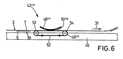
- the grinding device 42 "" has a great similarity to the grinding device according to FIG. 4. However, only one belt 52 is provided which is guided and driven around two deflection rollers 53, 54. Above the belt 52, a pressure plate 48 "" is provided, wherein a corresponding friction gap 50 "" is formed. By changing the relative speed between the belt 52 and the corrugated cardboard web 3, the intensity of the abrasion can be adjusted.
Abstract
Description
Die Erfindung betrifft eine Anlage sowie ein Verfahren zur Herstellung von mehrlagiger Wellpappe.The invention relates to a system and a method for producing multilayer corrugated board.
Die Herstellung mehrlagiger Wellpappe, insbesondere dreilagiger oder fünflagiger Wellpappe ist beispielsweise aus der
Der Erfindung liegt die Aufgabe zugrunde, eine Anlage sowie ein Verfahren zur Herstellung von Wellpappe zu schaffen, das die oben beschriebenen Nachteile des Standes der Technik überwindet.The invention has for its object to provide a system and a method for producing corrugated cardboard, which overcomes the disadvantages of the prior art described above.
Die Aufgabe wird durch die Merkmale der unabhängigen Ansprüche 1 und 10 gelöst. Der Kern der Erfindung besteht darin, die Wellenköpfe einer einseitig kaschierten Wellpappebahn vor deren Verklebung mit einer anderen Bahn zur Vergleichmäßigung von deren Oberfläche zu schleifen.The object is solved by the features of
Weitere vorteilhafte Ausgestaltung der Erfindung ergeben sich aus den Unteransprüchen.Further advantageous embodiment of the invention will become apparent from the dependent claims.
Zusätzliche Merkmale und Einzelheiten ergeben sich aus der nachfolgenden Beschreibung von fünf Ausführungsbeispielen anhand der Zeichnungen.Additional features and details will become apparent from the following description of five embodiments with reference to the drawings.
Es zeigen
- Fig. 1
- eine Seitenansicht einer Anlage zur Herstellung fünflagiger Wellpappe in schematischer Darstellung mit erfindungsgemäßen Schleif-Einrichtungen,
- Fig. 2
- eine Ausschnittvergrößerung einer Schleif-Einrichtung gemäß Fig. 1,
- Fig. 3
- eine Schleif-Einrichtung gemäß einem zweiten Ausführungsbeispiel,
- Fig. 4
- eine Schleif-Einrichtung gemäß einem dritten Ausführungsbeispiel,
- Fig. 5
- eine Schleif-Einrichtung gemäß einem vierten Ausführungsbeispiel,
- Fig. 6
- eine Schleif-Einrichtung gemäß einem fünften Ausführungsbeispiel.
- Fig. 1
- a side view of a plant for the production of five-ply corrugated cardboard in a schematic representation with grinding devices according to the invention,
- Fig. 2
- FIG. 1 a section enlargement of a grinding device according to FIG. 1, FIG.
- Fig. 3
- a grinding device according to a second embodiment,
- Fig. 4
- a grinding device according to a third embodiment,
- Fig. 5
- a grinding device according to a fourth embodiment,
- Fig. 6
- a grinding device according to a fifth embodiment.
Im Folgenden wird unter Bezugnahme auf die Fig. 1 und 2 eine erste Ausführungsform der Erfindung beschrieben. Die in Fig. 1 dargestellte Anlage zeigt rein schematisch - nur durch Gestelle angedeutet - zwei Maschinen 1, 2 zur Herstellung einseitig kaschierter Wellpappe. Aus beiden Maschinen 1, 2 kommt jeweils eine einseitig kaschierte Wellpappebahn 3 bzw. 4, deren gewellte Bahnen 5 bzw. 6 nach unten gerichtet sind. Beide Wellpappebahnen 3, 4 weisen obere glatte Deckbahnen 7 bzw. 8 auf, von denen die Deckbahn 7 der oberen Wellpappebahn 3 dicker ist als die Deckbahn 8 der unteren Wellpappebahn 4, die z. B. durch Papier von 60 bis 80 g/m2 gebildet sein kann. Derartige Maschinen zur Herstellung einseitig kaschierter Wellpappebahnen sind allgemein bekannt, beispielsweise aus der
Den beiden Maschinen 1, 2 sind jeweils Vorheiz-Stationen 9, 10 nachgeordnet, in denen jeweils eine angetriebene Zugwalze 11, 12 zum Abziehen der jeweiligen Wellpappebahn 3, 4 bzw. zum Einziehen dieser Wellpappebahn 3, 4 in die Vorheiz-Station 9 bzw. 10 vorgesehen ist. Der Zugwalze 11 bzw. 12 nachgeordnet ist jeweils ein Heizzylinder 13 bzw. 14 vorgesehen, über den die jeweilige Wellpappebahn 3 bzw. 4 in ihrer Deckbahn 7 bzw. 8 geführt wird. Unterhalb der unteren Vorheiz-Station 10 ist eine Abroll-Vorrichtung 15 für eine untere Deckbahn 16 vorgesehen, der ebenfalls eine Vorheiz-Station 17 mit einem Heizzylinder 18 für die untere Deckbahn 16 nachgeordnet ist. Die Zugwalzen 11, 12, die Heizzylinder 13, 14, 18 und die Abroll-Vorrichtung 15 sind in üblicher Weise angetrieben, was nicht im Einzelnen dargestellt ist.The two
Den beiden Vorheiz-Stationen 9, 10 für die Wellpappebahn 3, 4 sind Beleim-Vorrichtungen 19, 20 nachgeordnet, die jeweils eine Riffelwalze 21 bzw. 22 aufweisen, die an ihrer Außenseite mit einer der Wellung der gewellten Bahn 5 bzw. 6 in Form und Teilung entsprechenden Riffelung 23, 24 versehen sind. Mittels jeweils einer Umlenkwalze 25 bzw. 26 wird erreicht, dass die jeweilige Wellpappebahn 3 bzw. 4 über einen großen Umfangswinkel an dieser Riffelwalze 21 bzw. 22 anliegt. Die Riffelwalzen 21, 22 werden jeweils von einem drehzahlgeregelten Antriebsmotor 27, 28 angetrieben. Den Riffelwalzen 21 bzw. 22 ist jeweils ein Leimwerk 29 bzw. 30 nachgeordnet, in dem jeweils Leim auf die Spitzen der Wellung, d. h. die der jeweiligen Deckbahn 7, 8 abgewandten Wellenköpfe 39 der gewellten Bahnen 5, 6 aufgetragen wird. In Produktions-Richtung 31 den Leimwerken 29, 30 der Vorheiz-Station 17 nachgeordnet ist eine Heiz-Vorrichtung 32 vorgesehen, in der die Wellpappebahnen 3, 4 und die untere Deckbahn 16 zusammengeführt und miteinander verbunden werden. Die Heiz-Vorrichtung 32 weist ein Gestell 33 mit einer ebenen horizontalen Platte 34 auf, unterhalb derer Heiz-Elemente 35 vorgesehen sind. Oberhalb der Platte 34 sind in Produktions-Richtung 31 hintereinander mehrere Andrück-Elemente 36 vorgesehen, mittels derer die Gesamtheit der beiden Wellpappebahnen 3, 4 und der unteren Deckbahn 16 so auf die Platte 34 während des Transports durch die Heiz-Vorrichtung 32 in Produktions-Richtung 31 gedrückt werden, dass sie einerseits miteinander verleimt werden, andererseits aber die Wellungen der gewellten Bahnen 5, 6 nicht zerstört werden. Dabei werden die gewellte Bahn 5 und die Deckbahn 8 und die gewellte Bahn 6 mit der Deckbahn 16 verbunden. Zum gemeinsamen Einführen der Wellpappebahn 3, 4 und der unteren Deckbahn 16 in die Heiz-Vorrichtung 32 sind an dieser Einlaufwalzen 37, 38 vorgesehen. Entsprechende Heiz-Vorrichtungen 32 sind bekannt, beispielsweise aus der
Zwischen den Maschinen 1, 2 und den Vorheiz-Stationen 9 bzw. 10 sind zwei nachfolgend näher beschriebene Schleif-Einrichtungen 42, 43 vorgesehen, durch die die Wellpappebahnen 3 bzw. 4 geführt sind. Die Schleif-Einrichtungen 42, 43 können auch stattdessen alternativ den Vorheiz-Stationen 9, 10 nachgeordnet und den Beleimungs-Vorrichtungen 19, 20 vorgeordnet sein. Die Schleif-Einrichtungen gemäß dieser zweiten Alternative sind mit den Bezugzeichen 42A und 43A versehen. Die Schleif-Einrichtungen 42A, 43A sind den Heizzylindern 13, 14 nachgeordnet und befinden sich innerhalb - wie dargestellt - oder schon außerhalb der Vorheiz-Stationen 9, 10. Gemäß einer dritten Alternative ist es möglich, die Schleif-Einrichtungen in den Beleimungs-Vorrichtungen 19, 20, den Riffelwalzen 21, 22 nachgeordnet und den Leimwerken 29, 30 vorgeordnet vorzusehen. Gemäß dieser Alternative erhalten die Schleif-Einrichtungen die Bezugszeichen 42B und 43B. Im Grundsatz kommen alle Positionierungsmöglichkeiten nach der Herstellung der einseitig kaschierten Wellpappebahnen 3, 4 in Produktions-Richtung 31 vor den Leimwerken 29, 30 in Frage. Die verschiedenen Möglichkeiten der Anordnung der Schleif-Vorrichtungen 42, 43 gelten auch für die nachfolgend beschriebenen verschiedenen Ausführungsbeispiele der Schleif-Vorrichtungen.Between the
In Fig. 2 ist die Schleif-Einrichtung 42 vereinfacht dargestellt, wobei die Schleif-Vorrichtungen 42A, 42B, 43, 43A und 43B einen identischen Aufbau besitzen. Die Schleif-Vorrichtung 42 weist zwei voneinander beabstandet und parallel zueinander in ungefähr gleicher Höhe angeordnete, drehantreibbar gelagerte Umlenkwalzen 44, 45 auf. Zwischen den Walzen 44, 45 ist ein auf einem Träger 46 befestigter Tisch 47 vorgesehen. Oberhalb des Tisches 47 ist ein halbzylindermantelförmiges, sich über die Breite der Wellpappebahn 3 erstreckendes Umlenk-/Andrückblech 48 an einem nicht näher dargestellten Maschinengestell, gegenüber dem auch die Walzen 44, 45 gelagert sind, befestigt. Zwischen dem tiefsten Punkt des Blechs 48 und der Oberfläche 49 des Tisches 47 ist ein Reibspalt 50 gebildet, dessen Breite im wesentlichen der Dicke der Wellpappebahn 3 entspricht bzw. geringfügig schmaler als die Dicke der Wellpappebahn 3 ist. Auf der Oberfläche 49 ist eine sich über die Breite der Wellpappebahn 3 erstreckende abrasive Schleiffläche ausgebildet. Die Rauhigkeit der Oberfläche 49 ist der Dicke und Beschaffenheit der gewellten Bahn 5 angepasst. Die tangentiale Umfangsgeschwindigkeit vW der Walzen 44 und 45 entspricht der Geschwindigkeit vB der Wellpappebahn 3 in diesem Bereich, so dass zwischen den Walzen 44, 45 und der Bahn 3 kein Schlupf entsteht. Der tiefste Punkt des Umlenkbleches 48 liegt tiefer als die höchsten Punkte der Walzen 44, 45, so dass eine gewisse Umschlingung der Walzen 44, 45 erreicht wird.In Fig. 2, the
Im Folgenden wird die Funktionsweise der Erfindung gemäß dem ersten Ausführungsbeispiel beschrieben. Die zur Herstellung der einseitig kaschierten Wellpappebahnen 3, 4 verwendeten Riffelwalzen weisen über ihre Breite mehrere zueinander versetzte umlaufende Ringnuten auf. Diese Nuten sorgen dafür, dass in dem Beleimungswerk in der Maschine 1 bzw. 2 die gewellte Bahn 5 bzw. 6 durch Überdruck an der Riffelwalze hält. Durch das Aufschrumpfen der Papierbahn auf die mit Ringnuten versehene Riffelwalze entstehen im Bereich der Wellenköpfe Erhöhungen. Darüber hinaus ergeben sich vor allem bei der Verwendung bei minderwertigerem Papier für die gewellte Bahn 5 Schwankungen in der Ausbildung der Wellenköpfe 39. Die entsprechende Erhöhungen aufweisende Wellpappebahn 3 wird der Schleif-Vorrichtung 42 zugeführt. Hierbei wird die Bahn 3 zunächst der mitlaufenden Walze 44 zugeführt und um diese herum dem Reibspalt 50 zugeführt. In dem Reibspalt 50 werden die Wellenköpfe 39 über die Schleiffläche 49 geführt, wodurch eine Vergleichmäßigung der Oberfläche der Wellenköpfe 39 entsteht und die auf die Ringnuten der Riffelwalze zurückgehenden Erhöhungen abgeschliffen werden. Anschließend wird die Wellpappebahn 3 über die Walze 45 aus der Schleif-Vorrichtung 42 abgeführt. In dem nachgeordneten Leimwerk 29 erfolgt in Folge des Schleifvorganges eine gleichmäßige Beleimung des Wellenkopfes 39. Hierbei ist zum einen von Vorteil, dass die auf die Ringnuten der Riffelwalze zurückgehenden Erhöhungen abgetragen sind. Zum anderen resultiert die gleichmäßige Beleimung in einem geringfügigen Anschleifen der im Riffelwalzenspalt geprägten und verdichteten Oberfläche der Bahn 5 im Bereich des Wellenkopfes 39, so dass der Leim gleichmäßig aufgenommen werden kann. Bei dem anschließenden Zusammenführen der Wellenköpfe 39 der Bahn 3 mit der Deckbahn 8 bzw. der Wellenköpfe 39 der gewellten Bahn 6 mit der Deckbahn 16 kommt es zu einer stark verbesserten Verklebung. Das erfindungsgemäße Schleifverfahren kann bei Wellpappebahnen beliebiger Dicke und einer beliebigen Zahl verklebter Papierbahnen verwendet werden, solange auf der Außenseite eine gewellte Bahn verbleibt. Es kann somit, wie in Fig. 1 dargestellt, die gewellte Bahn einer einseitig kaschierten Wellpappebahn geschliffen werden. Es ist jedoch auch möglich, die gewellte Bahn einer bereits verklebten vierlagigen Wellpappebahn zu schleifen. Die Rauhigkeit der Schleiffläche 49 ist so gewählt, dass der Materialabtrag im Reibspalt 50 ausreichend, beispielsweise 2/100 mm ist, die gewellte Bahn 5 jedoch keinesfalls in ihrer Stabilität beeinträchtigt und sogar durchtrennt wird.In the following, the operation of the invention will be described according to the first embodiment. The corrugating rolls used for producing the
Im Folgenden wird unter Bezugnahme auf Fig. 3 ein zweites Ausführungsbeispiel einer erfindungsgemäßen Schleif-Vorrichtung 42' beschrieben. Konstruktiv identische Teile erhalten dieselben Bezugszeichen wie bei dem ersten Ausführungsbeispiel, auf dessen Beschreibung hiermit verwiesen wird. Konstruktiv unterschiedliche, jedoch funktionell gleichartige Teile erhalten dieselben Bezugszeichen mit einem hochgesetzten Strich. Wie bei dem Ausführungsbeispiel gemäß Fig. 2 ist ein ortsfester Tisch 47 mit einer Schleif-Oberfläche 49 vorgesehen. Oberhalb des Tisches 47 und durch einen Reibspalt 50' von der Oberfläche 49 des Tisches 47 entfernt ist eine drehantreibbar gelagerte Andrückwalze 51 vorgesehen. Die Walze 51 ist derart antreibbar, dass ihre tangentiale Umfangsgeschwindigkeit vW der Geschwindigkeit vB der Wellpappebahn 3 im Bereich der Walze 51 entspricht, d. h. zwischen der Walze 51 und der Wellpappebahn 3 besteht kein Schlupf. Die Wellenköpfe 39 der gewellten Bahn 5 werden gegen die Schleif-Oberfläche 49 gedrückt und hierdurch vergleichmäßigend abgeschliffen. Hinsichtlich der Erläuterung der sonstigen Funktionsweise wird auf die Beschreibung der Funktion des ersten Ausführungsbeispiels verwiesen.In the following, a second embodiment of a grinding device 42 'according to the invention will be described with reference to FIG. Structurally identical parts are given the same reference numerals as in the first embodiment, to the description of which reference is hereby made. Structurally different, but functionally similar parts get the same reference numerals with a prime. As in the embodiment of FIG. 2, a stationary table 47 is provided with a grinding
Im Folgenden wird unter Bezugnahme auf Fig. 4 eine drittes Ausführungsbeispiel der Schleif-Vorrichtung 42" beschrieben. Konstruktiv identische Teile erhalten dieselben Bezugszeichen wie bei dem ersten Ausführungsbeispiel, auf dessen Beschreibung hiermit verwiesen wird. Konstruktiv unterschiedliche, jedoch funktionell gleichartige Teile erhalten dieselben Bezugszeichen mit zwei hochgesetzten Strichen. Die Schleif-Vorrichtung 42" weist einen am Träger 46 befestigten Vakuum-Tisch 47" auf, an dessen Oberfläche über die Breite der Wellpappebahn 3 zahlreiche Vakuumdüsen zum Ansaugen der Wellpappebahn 3 vorgesehen sind. Der Tisch 47" wird in Längsrichtung von einem endlosen luftdurchlässigen Gurt 52 umgeben, der um zwei drehantreibbar gelagerte Umlenkrollen 53, 54 hinter bzw. vor dem Tisch 47" geführt ist. Der Gurt 52 liegt auf dem Tisch 47" auf. Er ist mit einer veränderlich einstellbaren Geschwindigkeit antreibbar, wobei auch die Bewegungsrichtung des Bandes auf dem Tisch in Produktionsrichtung 31 bzw. entgegen dieser einstellbar ist. Die Außenseite des Gurtes 52 weist eine abrasive Schleif-Oberfläche 49" auf. Oberhalb des Gurts 52 ist von diesem unter Bildung eines Reibspalts 50" beabstandet ein Andrückblech 48" befestigt, das die Wellpappebahn 3 gegen die Oberfläche 49" drückt und den Erhalt des Vakuums in den Vakuumdüsen am Tisch 47" durch deren Abdeckung begünstigt. Der Umfang des Abschleifens der Wellenköpfe 39 kann durch Veränderung der Relativgeschwindigkeit zwischen der Wellpappebahn 3 und dem Gurt 52 eingestellt werden. Dadurch, dass der Gurt 52 sowohl mitlaufend als auch gegenlaufend angetrieben werden kann, kann ein sehr großes Fenster verschiedener Abschleifintensitäten abgedeckt werden.A third embodiment of the grinding
Im Folgenden wird unter Bezugnahme auf Fig. 5 ein viertes Ausführungsbeispiel der Schleif-Vorrichtung 42'" beschrieben. Konstruktiv identische Teile erhalten dieselben Bezugszeichen wie bei dem ersten Ausführungsbeispiel, auf dessen Beschreibung hiermit verwiesen wird. Konstruktiv unterschiedliche, jedoch funktionell gleichartige Teile erhalten dieselben Bezugszeichen mit drei hochgesetzten Strichen. Wie bei dem Ausführungsbeispiel gemäß Fig. 2 sind zwei voneinander beabstandet angeordnete, drehantreibbar gelagerte Umlenkwalzen 44, 45 vorgesehen, um die die Wellpappebahn 3 geführt ist. Die tangentialen Umfangsgeschwindigkeiten der Walzen 44, 45 entsprechen der Geschwindigkeit der Wellpappebahn 3 im Bereich dieser Walzen, d. h. zwischen der Wellpappebahn 3 und den Walzen 44, 45 besteht kein Schlupf. Es ist auch möglich, die Walzen 44, 45 nicht drehbar gelagert auszubilden. Zwischen den Walzen 44 und 45 ist eine drehantreibbar gelagerte Schleifwalze 55 angeordnet. Diese ist gegenüber dem Maschinengestell abgestützt und durch einen Antriebsmotor 56 im Uhrzeigersinn und im Gegenuhrzeigersinn mit veränderlichen Geschwindigkeiten drehantreibbar. Die Walzen weisen über ihren Umfang eine Schleif-Oberfläche 49'" auf. Der oberste Punkt der Walze 55 liegt höher als der tiefste Punkt der Walzen 44, 45, so dass eine Umschlingung der Walze 55 durch die Bahn 3 entsteht. Durch eine Veränderung der Relativanordnung der Walze 55 zu den Walzen 44, 45 kann der Umschlingungswinkel a vergrößert bzw. verkleinert werden. Wie bei den vorherigen Ausführungsbeispielen wird der Umfang des Abschleifens bestimmt durch die Relativgeschwindigkeit zwischen der Wellpappebahn 3 und der Schleifwalze 55. Ein weiterer Einflussfaktor ist der Umschlingungswinkel a. Je größer der Umschlingungswinkel ist, um so größer ist die Abrasion. Zur Veränderung des Umschlingungswinkels sind die Walzen 44, 45, 55 in höhenverstellbaren Lagern 57 gelagert. Durch die Möglichkeit des Antriebs der Walze 55 im Uhrzeigersinn und im Gegenuhrzeigersinn kann ein großer Bereich von Relativgeschwindigkeiten abgedeckt werden.A fourth embodiment of the grinding
Im Folgenden wird unter Bezugnahme auf Fig. 6 ein fünftes Ausführungsbeispiel der Schleif-Vorrichtung 42"" beschrieben. Konstruktiv identische Teile erhalten dieselben Bezugszeichen wie bei dem ersten Ausführungsbeispiel, auf dessen Beschreibung hiermit verwiesen wird. Konstruktiv unterschiedliche, jedoch funktionell gleichartige Teile erhalten dieselben Bezugszeichen mit vier hochgesetzten Strichen. Die Schleif-Vorrichtung 42"" weist eine große Ähnlichkeit zu der Schleif-Vorrichtung gemäß Fig. 4 auf. Es ist jedoch lediglich ein Gurt 52 vorgesehen, der um zwei Umlenkrollen 53, 54 geführt und angetrieben wird. Oberhalb des Gurtes 52 ist ein Andrückblech 48"" vorgesehen, wobei ein entsprechender Reibspalt 50"" gebildet wird. Durch die Veränderung der Relativgeschwindigkeit zwischen dem Gurt 52 und der Wellpappebahn 3 kann die Intensität der Abrasion eingestellt werden.Hereinafter, a fifth embodiment of the grinding
Claims (10)
- Corrugated board system for producing multi-layered corrugated boarda. comprising at least one production arrangement (1, 2) for producing at least one corrugated board web (3, 4) lined on one side,i. wherein the corrugated board web (3, 4) has a corrugated web (5, 6) with outwardly projecting corrugation peaks (39),b. comprising at least one abrasive device (42, 43;-; 42"", 43"") arranged downstream of the at least one production arrangement (3, 4) in a production direction (31) for evening-out the surface of the corrugation peaks (39) by grinding,c. comprising a feed device (15) for feeding a material web andd. comprising a joining device (32) arranged downstream of the at least one abrasive device (42, 43;-; 42"", 43"") in the production direction (31) for joining the at least one corrugated board web (3, 4) to the material web.
- Corrugated board system according to claim 1, characterised in that the abrasive device (42, 43;-; 42"", 43"") has an abrasive member (49; 49"; 49"'; 49"") with an abrasive surface.
- Corrugated board system according to claim 2, characterised in that the at least one corrugated board web (3, 4) is guided over the abrasive member (49; 49"; 49"'; 49"").
- Corrugated board system according to claim 3, characterised in that the abrasive member (49) is arranged so as to be stationary.
- Corrugated board system according to claim 4, characterised in that a pressing device (48; 51; 48"; 48"") is provided for pressing the corrugated board web (3, 4) against the abrasive member (49; 49"; 49"").
- Corrugated board system according to claim 3, characterised in that the abrasive member (49"') is arranged on the surface of a roller (55) mounted so as to be rotationally drivable.
- Corrugated board system according to claim 6, characterised in that the roller (55) can be driven at a tangential circumferential velocity vW, which differs from the velocity vB of the corrugated board web (3, 4) in the region of the roller (55).
- Corrugated board system according to claim 1, characterised in that the material web is a single-layer cover web (16).
- Corrugated board system according to claim 1, characterised in that the material web is a corrugated board web lined on one side.
- Method for producing multi-layer corrugated board comprising the following steps:a. producing at least one corrugated board web (3, 4) lined on one side,i. wherein the corrugated board web (3, 4) has a corrugated web (5, 6) with outwardly projecting corrugation peaks (39),b. grinding the corrugation peaks (39) to even out the surface,c. joining the at least one corrugated board web (3, 4) to a material web.
Applications Claiming Priority (2)
| Application Number | Priority Date | Filing Date | Title |
|---|---|---|---|
| DE10245264 | 2002-09-27 | ||
| DE10245264A DE10245264A1 (en) | 2002-09-27 | 2002-09-27 | Corrugating machine |
Publications (3)
| Publication Number | Publication Date |
|---|---|
| EP1403034A2 EP1403034A2 (en) | 2004-03-31 |
| EP1403034A3 EP1403034A3 (en) | 2005-04-13 |
| EP1403034B1 true EP1403034B1 (en) | 2007-10-17 |
Family
ID=31969678
Family Applications (1)
| Application Number | Title | Priority Date | Filing Date |
|---|---|---|---|
| EP03015419A Expired - Lifetime EP1403034B1 (en) | 2002-09-27 | 2003-07-09 | Corrugated board manufacturing system |
Country Status (3)
| Country | Link |
|---|---|
| EP (1) | EP1403034B1 (en) |
| AT (1) | ATE375858T1 (en) |
| DE (2) | DE10245264A1 (en) |
Families Citing this family (3)
| Publication number | Priority date | Publication date | Assignee | Title |
|---|---|---|---|---|
| CN105935642A (en) * | 2016-05-31 | 2016-09-14 | 安徽浙源再生纸业科技有限公司 | Corrugated paper gumming machine |
| EP3315300B1 (en) | 2016-10-28 | 2019-04-24 | Neopost Technologies | Apparatus and method for creating corrugated cardboard on-site of systems for automatically forming packaging boxes |
| EP3521006B1 (en) | 2018-01-31 | 2020-11-25 | Quadient Technologies France | Method and system for creating custom-sized cardboard blanks for packagings and method and system for automatically packaging shipment sets in boxes |
Family Cites Families (4)
| Publication number | Priority date | Publication date | Assignee | Title |
|---|---|---|---|---|
| US5456783A (en) * | 1993-05-06 | 1995-10-10 | Interfic Developments Incorporated | Apparatus and method for enhancing heating uniformity for setting adhesive in corrugated paperboard manufacturing |
| DE4420726A1 (en) * | 1994-06-16 | 1995-12-21 | Bhs Corr Masch & Anlagenbau | Machine for producing a web of corrugated cardboard laminated at least on one side |
| DE19536007A1 (en) * | 1995-09-28 | 1997-04-03 | Bhs Corr Masch & Anlagenbau | Machine for producing a web of corrugated cardboard laminated at least on one side |
| DE19828124A1 (en) * | 1998-06-25 | 1999-12-30 | Bhs Corr Masch & Anlagenbau | Method for producing a metal foam workpiece |
-
2002
- 2002-09-27 DE DE10245264A patent/DE10245264A1/en not_active Withdrawn
-
2003
- 2003-07-09 DE DE50308403T patent/DE50308403D1/en not_active Expired - Fee Related
- 2003-07-09 EP EP03015419A patent/EP1403034B1/en not_active Expired - Lifetime
- 2003-07-09 AT AT03015419T patent/ATE375858T1/en not_active IP Right Cessation
Also Published As
| Publication number | Publication date |
|---|---|
| DE10245264A1 (en) | 2004-04-01 |
| EP1403034A2 (en) | 2004-03-31 |
| DE50308403D1 (en) | 2007-11-29 |
| EP1403034A3 (en) | 2005-04-13 |
| ATE375858T1 (en) | 2007-11-15 |
Similar Documents
| Publication | Publication Date | Title |
|---|---|---|
| EP1845046B1 (en) | Feeder-folder apparatus with device for scoring the sheets | |
| EP0934225B1 (en) | Device for folding a web of material | |
| DE2421771A1 (en) | MACHINE FOR THE PRODUCTION OF A WALK | |
| EP0664208B1 (en) | Apparatus for manufacturing a multilayer tube for making bags | |
| EP1905893B1 (en) | Tension roller for machine for manufacturing a corrugated cardboard sheet clad on at least one side and such a machine | |
| DE69813441T2 (en) | Single sided corrugated cardboard machine | |
| DE69825201T2 (en) | Single sided corrugator | |
| EP3459724B1 (en) | Corrugated cardboard assembly | |
| EP1270472B1 (en) | Web tension control device for a corrugated board machine | |
| EP0732996B1 (en) | Device and process for producing printed sheets | |
| DE2154889C3 (en) | Corrugated cardboard machine with corrugated rollers | |
| EP1403034B1 (en) | Corrugated board manufacturing system | |
| EP0901976B1 (en) | Arrangement of rollers in a folding apparatus of a rotary web printing press | |
| EP0518053B1 (en) | Method and apparatus for producing printed corrugated cardboard in large working widths | |
| DE69931828T2 (en) | Apparatus and method for producing a single-faced corrugated board | |
| DE2736741A1 (en) | METHOD AND DEVICE FOR GUIDING A FIBER FIBER FIBER THROUGH A COMPRESSION ZONE | |
| DE602004004104T2 (en) | DEVICE AND METHOD FOR PRODUCING MULTILAYER RAILED PRODUCTS | |
| DE3439374C2 (en) | Process for the production of corrugated cardboard and corrugated cardboard machine for carrying out the process | |
| EP0344685A2 (en) | Laminating machine in a corrugating installation | |
| DE1252521B (en) | Corrugating machine | |
| WO1999067083A1 (en) | Installation for producing 5-layered corrugated board | |
| DE2601265C3 (en) | Calender with three rolls in an L-arrangement | |
| DE4439403A1 (en) | Single side corrugated cardboard machine | |
| WO2022229022A2 (en) | Arrangement for producing a corrugated board web laminated on both sides | |
| WO2023117485A1 (en) | Liquid device |
Legal Events
| Date | Code | Title | Description |
|---|---|---|---|
| PUAI | Public reference made under article 153(3) epc to a published international application that has entered the european phase |
Free format text: ORIGINAL CODE: 0009012 |
|
| AK | Designated contracting states |
Kind code of ref document: A2 Designated state(s): AT BE BG CH CY CZ DE DK EE ES FI FR GB GR HU IE IT LI LU MC NL PT RO SE SI SK TR |
|
| AX | Request for extension of the european patent |
Extension state: AL LT LV MK |
|
| PUAL | Search report despatched |
Free format text: ORIGINAL CODE: 0009013 |
|
| AK | Designated contracting states |
Kind code of ref document: A3 Designated state(s): AT BE BG CH CY CZ DE DK EE ES FI FR GB GR HU IE IT LI LU MC NL PT RO SE SI SK TR |
|
| AX | Request for extension of the european patent |
Extension state: AL LT LV MK |
|
| 17P | Request for examination filed |
Effective date: 20050712 |
|
| AKX | Designation fees paid |
Designated state(s): AT BE BG CH CY CZ DE DK EE ES FI FR GB GR HU IE IT LI LU MC NL PT RO SE SI SK TR |
|
| GRAP | Despatch of communication of intention to grant a patent |
Free format text: ORIGINAL CODE: EPIDOSNIGR1 |
|
| GRAS | Grant fee paid |
Free format text: ORIGINAL CODE: EPIDOSNIGR3 |
|
| GRAA | (expected) grant |
Free format text: ORIGINAL CODE: 0009210 |
|
| AK | Designated contracting states |
Kind code of ref document: B1 Designated state(s): AT BE BG CH CY CZ DE DK EE ES FI FR GB GR HU IE IT LI LU MC NL PT RO SE SI SK TR |
|
| REG | Reference to a national code |
Ref country code: GB Ref legal event code: FG4D Free format text: NOT ENGLISH |
|
| GBT | Gb: translation of ep patent filed (gb section 77(6)(a)/1977) |
Effective date: 20071017 |
|
| REG | Reference to a national code |
Ref country code: CH Ref legal event code: EP |
|
| REG | Reference to a national code |
Ref country code: IE Ref legal event code: FG4D Free format text: LANGUAGE OF EP DOCUMENT: GERMAN |
|
| REF | Corresponds to: |
Ref document number: 50308403 Country of ref document: DE Date of ref document: 20071129 Kind code of ref document: P |
|
| ET | Fr: translation filed | ||
| NLV1 | Nl: lapsed or annulled due to failure to fulfill the requirements of art. 29p and 29m of the patents act | ||
| PG25 | Lapsed in a contracting state [announced via postgrant information from national office to epo] |
Ref country code: SE Free format text: LAPSE BECAUSE OF FAILURE TO SUBMIT A TRANSLATION OF THE DESCRIPTION OR TO PAY THE FEE WITHIN THE PRESCRIBED TIME-LIMIT Effective date: 20080117 Ref country code: NL Free format text: LAPSE BECAUSE OF FAILURE TO SUBMIT A TRANSLATION OF THE DESCRIPTION OR TO PAY THE FEE WITHIN THE PRESCRIBED TIME-LIMIT Effective date: 20071017 Ref country code: ES Free format text: LAPSE BECAUSE OF FAILURE TO SUBMIT A TRANSLATION OF THE DESCRIPTION OR TO PAY THE FEE WITHIN THE PRESCRIBED TIME-LIMIT Effective date: 20080128 |
|
| PG25 | Lapsed in a contracting state [announced via postgrant information from national office to epo] |
Ref country code: SI Free format text: LAPSE BECAUSE OF FAILURE TO SUBMIT A TRANSLATION OF THE DESCRIPTION OR TO PAY THE FEE WITHIN THE PRESCRIBED TIME-LIMIT Effective date: 20071017 Ref country code: BG Free format text: LAPSE BECAUSE OF FAILURE TO SUBMIT A TRANSLATION OF THE DESCRIPTION OR TO PAY THE FEE WITHIN THE PRESCRIBED TIME-LIMIT Effective date: 20080117 Ref country code: PT Free format text: LAPSE BECAUSE OF FAILURE TO SUBMIT A TRANSLATION OF THE DESCRIPTION OR TO PAY THE FEE WITHIN THE PRESCRIBED TIME-LIMIT Effective date: 20080317 |
|
| REG | Reference to a national code |
Ref country code: IE Ref legal event code: FD4D |
|
| PG25 | Lapsed in a contracting state [announced via postgrant information from national office to epo] |
Ref country code: CZ Free format text: LAPSE BECAUSE OF FAILURE TO SUBMIT A TRANSLATION OF THE DESCRIPTION OR TO PAY THE FEE WITHIN THE PRESCRIBED TIME-LIMIT Effective date: 20071017 Ref country code: DK Free format text: LAPSE BECAUSE OF FAILURE TO SUBMIT A TRANSLATION OF THE DESCRIPTION OR TO PAY THE FEE WITHIN THE PRESCRIBED TIME-LIMIT Effective date: 20071017 |
|
| PLBE | No opposition filed within time limit |
Free format text: ORIGINAL CODE: 0009261 |
|
| STAA | Information on the status of an ep patent application or granted ep patent |
Free format text: STATUS: NO OPPOSITION FILED WITHIN TIME LIMIT |
|
| PG25 | Lapsed in a contracting state [announced via postgrant information from national office to epo] |
Ref country code: SK Free format text: LAPSE BECAUSE OF FAILURE TO SUBMIT A TRANSLATION OF THE DESCRIPTION OR TO PAY THE FEE WITHIN THE PRESCRIBED TIME-LIMIT Effective date: 20071017 Ref country code: RO Free format text: LAPSE BECAUSE OF FAILURE TO SUBMIT A TRANSLATION OF THE DESCRIPTION OR TO PAY THE FEE WITHIN THE PRESCRIBED TIME-LIMIT Effective date: 20071017 |
|
| 26N | No opposition filed |
Effective date: 20080718 |
|
| PG25 | Lapsed in a contracting state [announced via postgrant information from national office to epo] |
Ref country code: IE Free format text: LAPSE BECAUSE OF FAILURE TO SUBMIT A TRANSLATION OF THE DESCRIPTION OR TO PAY THE FEE WITHIN THE PRESCRIBED TIME-LIMIT Effective date: 20071017 |
|
| PG25 | Lapsed in a contracting state [announced via postgrant information from national office to epo] |
Ref country code: GR Free format text: LAPSE BECAUSE OF FAILURE TO SUBMIT A TRANSLATION OF THE DESCRIPTION OR TO PAY THE FEE WITHIN THE PRESCRIBED TIME-LIMIT Effective date: 20080118 |
|
| PGFP | Annual fee paid to national office [announced via postgrant information from national office to epo] |
Ref country code: DE Payment date: 20080923 Year of fee payment: 6 |
|
| PG25 | Lapsed in a contracting state [announced via postgrant information from national office to epo] |
Ref country code: FI Free format text: LAPSE BECAUSE OF FAILURE TO SUBMIT A TRANSLATION OF THE DESCRIPTION OR TO PAY THE FEE WITHIN THE PRESCRIBED TIME-LIMIT Effective date: 20071017 |
|
| REG | Reference to a national code |
Ref country code: CH Ref legal event code: PL |
|
| PG25 | Lapsed in a contracting state [announced via postgrant information from national office to epo] |
Ref country code: MC Free format text: LAPSE BECAUSE OF NON-PAYMENT OF DUE FEES Effective date: 20080731 |
|
| PG25 | Lapsed in a contracting state [announced via postgrant information from national office to epo] |
Ref country code: EE Free format text: LAPSE BECAUSE OF FAILURE TO SUBMIT A TRANSLATION OF THE DESCRIPTION OR TO PAY THE FEE WITHIN THE PRESCRIBED TIME-LIMIT Effective date: 20071017 |
|
| PG25 | Lapsed in a contracting state [announced via postgrant information from national office to epo] |
Ref country code: CH Free format text: LAPSE BECAUSE OF NON-PAYMENT OF DUE FEES Effective date: 20080731 Ref country code: LI Free format text: LAPSE BECAUSE OF NON-PAYMENT OF DUE FEES Effective date: 20080731 |
|
| PG25 | Lapsed in a contracting state [announced via postgrant information from national office to epo] |
Ref country code: CY Free format text: LAPSE BECAUSE OF FAILURE TO SUBMIT A TRANSLATION OF THE DESCRIPTION OR TO PAY THE FEE WITHIN THE PRESCRIBED TIME-LIMIT Effective date: 20071017 |
|
| PG25 | Lapsed in a contracting state [announced via postgrant information from national office to epo] |
Ref country code: AT Free format text: LAPSE BECAUSE OF NON-PAYMENT OF DUE FEES Effective date: 20080709 |
|
| PGFP | Annual fee paid to national office [announced via postgrant information from national office to epo] |
Ref country code: GB Payment date: 20090724 Year of fee payment: 7 |
|
| PG25 | Lapsed in a contracting state [announced via postgrant information from national office to epo] |
Ref country code: DE Free format text: LAPSE BECAUSE OF NON-PAYMENT OF DUE FEES Effective date: 20100202 |
|
| PG25 | Lapsed in a contracting state [announced via postgrant information from national office to epo] |
Ref country code: LU Free format text: LAPSE BECAUSE OF NON-PAYMENT OF DUE FEES Effective date: 20080709 Ref country code: BE Free format text: LAPSE BECAUSE OF NON-PAYMENT OF DUE FEES Effective date: 20080731 Ref country code: HU Free format text: LAPSE BECAUSE OF FAILURE TO SUBMIT A TRANSLATION OF THE DESCRIPTION OR TO PAY THE FEE WITHIN THE PRESCRIBED TIME-LIMIT Effective date: 20080418 |
|
| PG25 | Lapsed in a contracting state [announced via postgrant information from national office to epo] |
Ref country code: TR Free format text: LAPSE BECAUSE OF FAILURE TO SUBMIT A TRANSLATION OF THE DESCRIPTION OR TO PAY THE FEE WITHIN THE PRESCRIBED TIME-LIMIT Effective date: 20071017 |
|
| GBPC | Gb: european patent ceased through non-payment of renewal fee |
Effective date: 20100709 |
|
| PG25 | Lapsed in a contracting state [announced via postgrant information from national office to epo] |
Ref country code: GB Free format text: LAPSE BECAUSE OF NON-PAYMENT OF DUE FEES Effective date: 20100709 |
|
| PGFP | Annual fee paid to national office [announced via postgrant information from national office to epo] |
Ref country code: FR Payment date: 20140724 Year of fee payment: 12 |
|
| PGFP | Annual fee paid to national office [announced via postgrant information from national office to epo] |
Ref country code: IT Payment date: 20140728 Year of fee payment: 12 |
|
| PG25 | Lapsed in a contracting state [announced via postgrant information from national office to epo] |
Ref country code: IT Free format text: LAPSE BECAUSE OF NON-PAYMENT OF DUE FEES Effective date: 20150709 |
|
| REG | Reference to a national code |
Ref country code: FR Ref legal event code: ST Effective date: 20160331 |
|
| PG25 | Lapsed in a contracting state [announced via postgrant information from national office to epo] |
Ref country code: FR Free format text: LAPSE BECAUSE OF NON-PAYMENT OF DUE FEES Effective date: 20150731 |