EP3459724B1 - Corrugated cardboard assembly - Google Patents
Corrugated cardboard assembly Download PDFInfo
- Publication number
- EP3459724B1 EP3459724B1 EP18192145.3A EP18192145A EP3459724B1 EP 3459724 B1 EP3459724 B1 EP 3459724B1 EP 18192145 A EP18192145 A EP 18192145A EP 3459724 B1 EP3459724 B1 EP 3459724B1
- Authority
- EP
- European Patent Office
- Prior art keywords
- web
- corrugated cardboard
- laminated
- producing
- corrugated
- Prior art date
- Legal status (The legal status is an assumption and is not a legal conclusion. Google has not performed a legal analysis and makes no representation as to the accuracy of the status listed.)
- Active
Links
- 239000003292 glue Substances 0.000 claims description 73
- 238000007639 printing Methods 0.000 claims description 72
- 238000004026 adhesive bonding Methods 0.000 claims description 58
- 239000000463 material Substances 0.000 claims description 47
- 238000003825 pressing Methods 0.000 claims description 33
- 238000003475 lamination Methods 0.000 claims description 30
- 238000011144 upstream manufacturing Methods 0.000 claims description 20
- 238000009434 installation Methods 0.000 claims 7
- 238000010030 laminating Methods 0.000 description 86
- 238000005520 cutting process Methods 0.000 description 17
- 238000007641 inkjet printing Methods 0.000 description 12
- 238000001035 drying Methods 0.000 description 7
- 230000001419 dependent effect Effects 0.000 description 6
- 239000011248 coating agent Substances 0.000 description 5
- 238000000576 coating method Methods 0.000 description 5
- 230000006835 compression Effects 0.000 description 5
- 238000007906 compression Methods 0.000 description 5
- 238000007603 infrared drying Methods 0.000 description 5
- 238000010438 heat treatment Methods 0.000 description 4
- 238000007602 hot air drying Methods 0.000 description 3
- 230000015572 biosynthetic process Effects 0.000 description 2
- 230000000694 effects Effects 0.000 description 2
- 230000005484 gravity Effects 0.000 description 2
- SWQJXJOGLNCZEY-UHFFFAOYSA-N helium atom Chemical compound [He] SWQJXJOGLNCZEY-UHFFFAOYSA-N 0.000 description 2
- 230000006978 adaptation Effects 0.000 description 1
- 239000000853 adhesive Substances 0.000 description 1
- 230000001070 adhesive effect Effects 0.000 description 1
- 239000003795 chemical substances by application Substances 0.000 description 1
- 239000003086 colorant Substances 0.000 description 1
- 238000001816 cooling Methods 0.000 description 1
- 230000014509 gene expression Effects 0.000 description 1
- 238000009499 grossing Methods 0.000 description 1
- 238000004519 manufacturing process Methods 0.000 description 1
- 238000000034 method Methods 0.000 description 1
- 230000003647 oxidation Effects 0.000 description 1
- 238000007254 oxidation reaction Methods 0.000 description 1
- 239000003973 paint Substances 0.000 description 1
- 238000002360 preparation method Methods 0.000 description 1
- 238000002203 pretreatment Methods 0.000 description 1
- 230000005855 radiation Effects 0.000 description 1
- 239000000758 substrate Substances 0.000 description 1
- 208000008918 voyeurism Diseases 0.000 description 1
Images


Classifications
-
- B—PERFORMING OPERATIONS; TRANSPORTING
- B31—MAKING ARTICLES OF PAPER, CARDBOARD OR MATERIAL WORKED IN A MANNER ANALOGOUS TO PAPER; WORKING PAPER, CARDBOARD OR MATERIAL WORKED IN A MANNER ANALOGOUS TO PAPER
- B31F—MECHANICAL WORKING OR DEFORMATION OF PAPER, CARDBOARD OR MATERIAL WORKED IN A MANNER ANALOGOUS TO PAPER
- B31F1/00—Mechanical deformation without removing material, e.g. in combination with laminating
- B31F1/20—Corrugating; Corrugating combined with laminating to other layers
- B31F1/24—Making webs in which the channel of each corrugation is transverse to the web feed
- B31F1/26—Making webs in which the channel of each corrugation is transverse to the web feed by interengaging toothed cylinders cylinder constructions
- B31F1/28—Making webs in which the channel of each corrugation is transverse to the web feed by interengaging toothed cylinders cylinder constructions combined with uniting the corrugated webs to flat webs ; Making double-faced corrugated cardboard
- B31F1/2845—Details, e.g. provisions for drying, moistening, pressing
- B31F1/2877—Pressing means for bringing facer sheet and corrugated webs into contact or keeping them in contact, e.g. rolls, belts
-
- B—PERFORMING OPERATIONS; TRANSPORTING
- B31—MAKING ARTICLES OF PAPER, CARDBOARD OR MATERIAL WORKED IN A MANNER ANALOGOUS TO PAPER; WORKING PAPER, CARDBOARD OR MATERIAL WORKED IN A MANNER ANALOGOUS TO PAPER
- B31F—MECHANICAL WORKING OR DEFORMATION OF PAPER, CARDBOARD OR MATERIAL WORKED IN A MANNER ANALOGOUS TO PAPER
- B31F1/00—Mechanical deformation without removing material, e.g. in combination with laminating
- B31F1/20—Corrugating; Corrugating combined with laminating to other layers
- B31F1/24—Making webs in which the channel of each corrugation is transverse to the web feed
- B31F1/26—Making webs in which the channel of each corrugation is transverse to the web feed by interengaging toothed cylinders cylinder constructions
- B31F1/28—Making webs in which the channel of each corrugation is transverse to the web feed by interengaging toothed cylinders cylinder constructions combined with uniting the corrugated webs to flat webs ; Making double-faced corrugated cardboard
- B31F1/2813—Making corrugated cardboard of composite structure, e.g. comprising two or more corrugated layers
-
- B—PERFORMING OPERATIONS; TRANSPORTING
- B31—MAKING ARTICLES OF PAPER, CARDBOARD OR MATERIAL WORKED IN A MANNER ANALOGOUS TO PAPER; WORKING PAPER, CARDBOARD OR MATERIAL WORKED IN A MANNER ANALOGOUS TO PAPER
- B31F—MECHANICAL WORKING OR DEFORMATION OF PAPER, CARDBOARD OR MATERIAL WORKED IN A MANNER ANALOGOUS TO PAPER
- B31F1/00—Mechanical deformation without removing material, e.g. in combination with laminating
- B31F1/20—Corrugating; Corrugating combined with laminating to other layers
- B31F1/24—Making webs in which the channel of each corrugation is transverse to the web feed
- B31F1/26—Making webs in which the channel of each corrugation is transverse to the web feed by interengaging toothed cylinders cylinder constructions
- B31F1/28—Making webs in which the channel of each corrugation is transverse to the web feed by interengaging toothed cylinders cylinder constructions combined with uniting the corrugated webs to flat webs ; Making double-faced corrugated cardboard
- B31F1/2818—Glue application specially adapted therefor
-
- B—PERFORMING OPERATIONS; TRANSPORTING
- B31—MAKING ARTICLES OF PAPER, CARDBOARD OR MATERIAL WORKED IN A MANNER ANALOGOUS TO PAPER; WORKING PAPER, CARDBOARD OR MATERIAL WORKED IN A MANNER ANALOGOUS TO PAPER
- B31F—MECHANICAL WORKING OR DEFORMATION OF PAPER, CARDBOARD OR MATERIAL WORKED IN A MANNER ANALOGOUS TO PAPER
- B31F1/00—Mechanical deformation without removing material, e.g. in combination with laminating
- B31F1/20—Corrugating; Corrugating combined with laminating to other layers
- B31F1/24—Making webs in which the channel of each corrugation is transverse to the web feed
- B31F1/26—Making webs in which the channel of each corrugation is transverse to the web feed by interengaging toothed cylinders cylinder constructions
- B31F1/28—Making webs in which the channel of each corrugation is transverse to the web feed by interengaging toothed cylinders cylinder constructions combined with uniting the corrugated webs to flat webs ; Making double-faced corrugated cardboard
- B31F1/2822—Making webs in which the channel of each corrugation is transverse to the web feed by interengaging toothed cylinders cylinder constructions combined with uniting the corrugated webs to flat webs ; Making double-faced corrugated cardboard involving additional operations
-
- B—PERFORMING OPERATIONS; TRANSPORTING
- B31—MAKING ARTICLES OF PAPER, CARDBOARD OR MATERIAL WORKED IN A MANNER ANALOGOUS TO PAPER; WORKING PAPER, CARDBOARD OR MATERIAL WORKED IN A MANNER ANALOGOUS TO PAPER
- B31F—MECHANICAL WORKING OR DEFORMATION OF PAPER, CARDBOARD OR MATERIAL WORKED IN A MANNER ANALOGOUS TO PAPER
- B31F1/00—Mechanical deformation without removing material, e.g. in combination with laminating
- B31F1/20—Corrugating; Corrugating combined with laminating to other layers
- B31F1/24—Making webs in which the channel of each corrugation is transverse to the web feed
- B31F1/26—Making webs in which the channel of each corrugation is transverse to the web feed by interengaging toothed cylinders cylinder constructions
- B31F1/28—Making webs in which the channel of each corrugation is transverse to the web feed by interengaging toothed cylinders cylinder constructions combined with uniting the corrugated webs to flat webs ; Making double-faced corrugated cardboard
- B31F1/2831—Control
- B31F1/2836—Guiding, e.g. edge alignment; Tensioning
-
- B—PERFORMING OPERATIONS; TRANSPORTING
- B31—MAKING ARTICLES OF PAPER, CARDBOARD OR MATERIAL WORKED IN A MANNER ANALOGOUS TO PAPER; WORKING PAPER, CARDBOARD OR MATERIAL WORKED IN A MANNER ANALOGOUS TO PAPER
- B31F—MECHANICAL WORKING OR DEFORMATION OF PAPER, CARDBOARD OR MATERIAL WORKED IN A MANNER ANALOGOUS TO PAPER
- B31F1/00—Mechanical deformation without removing material, e.g. in combination with laminating
- B31F1/20—Corrugating; Corrugating combined with laminating to other layers
- B31F1/24—Making webs in which the channel of each corrugation is transverse to the web feed
- B31F1/26—Making webs in which the channel of each corrugation is transverse to the web feed by interengaging toothed cylinders cylinder constructions
- B31F1/28—Making webs in which the channel of each corrugation is transverse to the web feed by interengaging toothed cylinders cylinder constructions combined with uniting the corrugated webs to flat webs ; Making double-faced corrugated cardboard
- B31F1/2845—Details, e.g. provisions for drying, moistening, pressing
- B31F1/285—Heating or drying equipment
-
- B—PERFORMING OPERATIONS; TRANSPORTING
- B31—MAKING ARTICLES OF PAPER, CARDBOARD OR MATERIAL WORKED IN A MANNER ANALOGOUS TO PAPER; WORKING PAPER, CARDBOARD OR MATERIAL WORKED IN A MANNER ANALOGOUS TO PAPER
- B31F—MECHANICAL WORKING OR DEFORMATION OF PAPER, CARDBOARD OR MATERIAL WORKED IN A MANNER ANALOGOUS TO PAPER
- B31F5/00—Attaching together sheets, strips or webs; Reinforcing edges
- B31F5/04—Attaching together sheets, strips or webs; Reinforcing edges by exclusive use of adhesives
-
- B—PERFORMING OPERATIONS; TRANSPORTING
- B41—PRINTING; LINING MACHINES; TYPEWRITERS; STAMPS
- B41J—TYPEWRITERS; SELECTIVE PRINTING MECHANISMS, i.e. MECHANISMS PRINTING OTHERWISE THAN FROM A FORME; CORRECTION OF TYPOGRAPHICAL ERRORS
- B41J11/00—Devices or arrangements of selective printing mechanisms, e.g. ink-jet printers or thermal printers, for supporting or handling copy material in sheet or web form
- B41J11/0015—Devices or arrangements of selective printing mechanisms, e.g. ink-jet printers or thermal printers, for supporting or handling copy material in sheet or web form for treating before, during or after printing or for uniform coating or laminating the copy material before or after printing
- B41J11/002—Curing or drying the ink on the copy materials, e.g. by heating or irradiating
-
- B—PERFORMING OPERATIONS; TRANSPORTING
- B41—PRINTING; LINING MACHINES; TYPEWRITERS; STAMPS
- B41J—TYPEWRITERS; SELECTIVE PRINTING MECHANISMS, i.e. MECHANISMS PRINTING OTHERWISE THAN FROM A FORME; CORRECTION OF TYPOGRAPHICAL ERRORS
- B41J11/00—Devices or arrangements of selective printing mechanisms, e.g. ink-jet printers or thermal printers, for supporting or handling copy material in sheet or web form
- B41J11/66—Applications of cutting devices
- B41J11/68—Applications of cutting devices cutting parallel to the direction of paper feed
-
- B—PERFORMING OPERATIONS; TRANSPORTING
- B41—PRINTING; LINING MACHINES; TYPEWRITERS; STAMPS
- B41J—TYPEWRITERS; SELECTIVE PRINTING MECHANISMS, i.e. MECHANISMS PRINTING OTHERWISE THAN FROM A FORME; CORRECTION OF TYPOGRAPHICAL ERRORS
- B41J11/00—Devices or arrangements of selective printing mechanisms, e.g. ink-jet printers or thermal printers, for supporting or handling copy material in sheet or web form
- B41J11/66—Applications of cutting devices
- B41J11/70—Applications of cutting devices cutting perpendicular to the direction of paper feed
- B41J11/703—Cutting of tape
-
- B—PERFORMING OPERATIONS; TRANSPORTING
- B41—PRINTING; LINING MACHINES; TYPEWRITERS; STAMPS
- B41J—TYPEWRITERS; SELECTIVE PRINTING MECHANISMS, i.e. MECHANISMS PRINTING OTHERWISE THAN FROM A FORME; CORRECTION OF TYPOGRAPHICAL ERRORS
- B41J15/00—Devices or arrangements of selective printing mechanisms, e.g. ink-jet printers or thermal printers, specially adapted for supporting or handling copy material in continuous form, e.g. webs
-
- B—PERFORMING OPERATIONS; TRANSPORTING
- B31—MAKING ARTICLES OF PAPER, CARDBOARD OR MATERIAL WORKED IN A MANNER ANALOGOUS TO PAPER; WORKING PAPER, CARDBOARD OR MATERIAL WORKED IN A MANNER ANALOGOUS TO PAPER
- B31F—MECHANICAL WORKING OR DEFORMATION OF PAPER, CARDBOARD OR MATERIAL WORKED IN A MANNER ANALOGOUS TO PAPER
- B31F1/00—Mechanical deformation without removing material, e.g. in combination with laminating
- B31F1/20—Corrugating; Corrugating combined with laminating to other layers
- B31F1/24—Making webs in which the channel of each corrugation is transverse to the web feed
- B31F1/26—Making webs in which the channel of each corrugation is transverse to the web feed by interengaging toothed cylinders cylinder constructions
- B31F1/28—Making webs in which the channel of each corrugation is transverse to the web feed by interengaging toothed cylinders cylinder constructions combined with uniting the corrugated webs to flat webs ; Making double-faced corrugated cardboard
- B31F1/2845—Details, e.g. provisions for drying, moistening, pressing
- B31F1/2854—Means for keeping the sheet in contact with one of the corrugating rollers after corrugating, but before applying the facer sheet, e.g. by air pressure, suction or pressing fingers
-
- B—PERFORMING OPERATIONS; TRANSPORTING
- B32—LAYERED PRODUCTS
- B32B—LAYERED PRODUCTS, i.e. PRODUCTS BUILT-UP OF STRATA OF FLAT OR NON-FLAT, e.g. CELLULAR OR HONEYCOMB, FORM
- B32B2309/00—Parameters for the laminating or treatment process; Apparatus details
- B32B2309/08—Dimensions, e.g. volume
-
- B—PERFORMING OPERATIONS; TRANSPORTING
- B32—LAYERED PRODUCTS
- B32B—LAYERED PRODUCTS, i.e. PRODUCTS BUILT-UP OF STRATA OF FLAT OR NON-FLAT, e.g. CELLULAR OR HONEYCOMB, FORM
- B32B37/00—Methods or apparatus for laminating, e.g. by curing or by ultrasonic bonding
- B32B37/0046—Methods or apparatus for laminating, e.g. by curing or by ultrasonic bonding characterised by constructional aspects of the apparatus
-
- B—PERFORMING OPERATIONS; TRANSPORTING
- B32—LAYERED PRODUCTS
- B32B—LAYERED PRODUCTS, i.e. PRODUCTS BUILT-UP OF STRATA OF FLAT OR NON-FLAT, e.g. CELLULAR OR HONEYCOMB, FORM
- B32B37/00—Methods or apparatus for laminating, e.g. by curing or by ultrasonic bonding
- B32B37/12—Methods or apparatus for laminating, e.g. by curing or by ultrasonic bonding characterised by using adhesives
- B32B37/1284—Application of adhesive
Definitions
- the invention relates to a corrugated cardboard plant according to the preamble of claim 1.
- Corrugated cardboard systems with printing arrangements are generally known from the prior art due to prior public use.
- the quality of the printing by the printing arrangements is often unsatisfactory.
- a liner is printed in the Helio printing device.
- a web of material is corrugated, which is laminated onto a web of material to form a web of corrugated cardboard laminated on one side.
- the one-sided laminated corrugated cardboard web and the lamination web, which is located above the one-sided laminated corrugated cardboard web, are joined together in an adhesive device.
- the corrugation of the corrugated cardboard web laminated on one side faces upwards in front of the gluing device.
- the EP 2 551 117 A2 teaches the management of a glued corrugated sheet and a cover sheet to a corrugated board machine.
- a laminated liner web is glued to these webs by means of pressure rollers.
- the liner can be printed on by means of a printing device.
- the corrugated sheet of the corrugated cardboard sheet laminated on one side is directed upwards immediately upstream of the pressure rollers.
- the laminating web is located on the pressure rollers above the one-sided laminated corrugated cardboard web.
- the U.S. 4,169,007 discloses a corrugated cardboard plant in which a one-sided laminated corrugated cardboard web with upwardly directed corrugation by a Drying-cooling machine is performed, where it is glued to a liner.
- a corrugated cardboard plant which comprises a single-sided corrugated cardboard machine and a double-sided corrugated cardboard machine arranged above it.
- the corrugated sheet of a sheet of corrugated cardboard laminated on one side is directed upwards immediately upstream of the double-sided corrugated cardboard machine.
- a lamination web is located in the double-sided corrugated board machine above the single-sided laminated corrugated board web. The liner can already be printed.
- the EP 2 792 478 A1 discloses a corrugated cardboard plant with a device for producing a web of corrugated cardboard laminated on one side.
- the web of corrugated cardboard laminated on one side is fed to a device for producing a web of corrugated cardboard laminated on both sides.
- a corrugated sheet of the corrugated cardboard sheet laminated on one side faces upwards immediately upstream of the device for producing a sheet of corrugated cardboard laminated on both sides.
- a liner web is fed from above into the device for producing a double-sided laminated corrugated cardboard web and is located there above the one-sided laminated corrugated cardboard web.
- the invention is based on the object of creating a corrugated cardboard system with a printing arrangement which requires a comparatively small amount of space. Furthermore, the print quality or corrugated board quality should be particularly high.
- the core of the corrugated cardboard system according to the invention is that, by means of a laminating web printing arrangement, the laminating web, in particular temporally and / or locally, before the formation of a double-sided laminated corrugated board web in the device for producing a double-sided laminated corrugated board web, i.e. before connection to a one-sided laminated corrugated cardboard web, is printed.
- the laminating web printing arrangement prints the conveyed, in particular still unbound, laminating web on an outer print side.
- the lamination web is or remains a smooth, non-corrugated web.
- the web of corrugated cardboard laminated on both sides has at least three layers, preferably three, five or seven layers.
- the at least one web of corrugated cardboard laminated on one side has a respective upwardly directed corrugation adjacent to the device for producing a double-sided laminated corrugated cardboard web and in particular also in this.
- the corrugated sheet is located there above the associated / assigned cover sheet of the respective single-sided laminated sheet of corrugated cardboard.
- the device for producing a double-sided laminated corrugated cardboard web laminates the laminating web from above onto the adjacent one-sided laminated corrugated cardboard web.
- the laminating web printing arrangement is advantageously designed as a digital printing arrangement, in particular an inkjet printing arrangement. It can preferably be retrofitted. Other known pressure arrangements can alternatively be used.
- the laminating web printing arrangement is in particular capable of printing at least one letter, a number, another character, a graphic and / or a photo onto the laminating web. For that will favorably color or ink is used. It is advantageous if the liner printing arrangement is capable of printing in multiple colors.
- the laminating web printing arrangement advantageously has a plurality of print heads cascaded in the transverse direction in the laminating web.
- the laminating web printing arrangement preferably has several rows of print heads arranged one behind the other. It is advantageous if the liner web to be printed in the liner web printing arrangement is guided over a printing cylinder or central cylinder during printing.
- the printing cylinder preferably extends horizontally and perpendicular to a conveying direction of the laminating web.
- At least one cover sheet dispensing device expediently dispenses the respective cover sheet. It is expedient if the at least one cover web dispensing device is designed as a splice device for providing a respective endless cover web.
- At least one material web dispensing device preferably dispenses the respective material web. It is advantageous if the at least one material web dispensing device is designed as a splicing device for providing a respective endless material web.
- the laminating web dispensing device is preferably designed as a splicing device for providing an endless laminating web.
- the device for producing a corrugated cardboard web laminated on both sides advantageously connects the at least one corrugated cardboard web laminated on one side to the, in particular printed, laminating web.
- the device for producing a double-sided laminated corrugated cardboard web has preferably at least one pressing gap or at least one pressing section through which the at least one web of corrugated cardboard laminated on one side and the laminating web are guided and pressed together. Between the strips there is preferably glue for the gluing connection of the same.
- the at least one compression gap or the at least one compression section is advantageously formed or delimited by at least two, in particular drivable, compression rollers or compression belts arranged in pairs.
- the compression belts are preferably endless.
- Each corrugating device is advantageously formed by two rotatably mounted corrugating rollers.
- the corrugated rollers form a roller gap or corrugated gap for guiding through and corrugating the respective material web to form a corrugated web.
- the pressing device expediently presses the respective cover sheet against the corrugated sheet, which preferably rests against the adjacent corrugated roller.
- the pressing device is designed as a pressing belt module.
- the web of corrugated cardboard laminated on one side preferably leaves the respective pressing device via a respective pressing outlet which faces away from the device for producing a web of corrugated cardboard laminated on both sides.
- the pressing input and output of the respective pressing device are advantageously arranged at a distance from one another.
- the at least one deflection arrangement advantageously has at least one deflection roller or rod.
- the at least one deflection roller or rod extends preferably perpendicular to the associated web of corrugated cardboard laminated on one side or to its conveying direction and horizontally.
- the at least one deflection arrangement is, for example, part of the at least one device for producing a web of corrugated cardboard laminated on one side and / or a bridge. Alternatively, this is implemented separately and arranged, for example, between the at least one device for producing a web of corrugated cardboard laminated on one side and the bridge.
- the processing temperatures of the glue of below 70 ° C mean that particularly little energy is required to manufacture the corrugated cardboard. Furthermore, the webs to be glued or connected to one another are protected.
- the glue has a comparatively low setting temperature or curing temperature.
- the at least one glue application device preferably each has a glue metering roller, a glue container and a glue application roller.
- the corresponding glue application roller preferably forms a glue gap with a corrugated roller.
- the glue located in the glue container is expediently applied to the tips of the corrugation of the corrugated sheet via the glue application roller.
- the glue metering roller preferably rests against the neighboring glue application roller and serves to form a uniform glue layer on the glue application roller.
- the gluing unit according to dependent claim 3 advantageously applies glue from above to the tips of the corrugation of the at least one sheet of corrugated cardboard laminated on one side. This application is favorably supported by gravity.
- the glue used in the glue unit preferably allows processing temperatures below 70 ° C.
- This glue unit has a particularly low energy requirement.
- Corrugated cardboard can thus be produced extremely economically.
- particularly little moisture is preferably introduced into the at least one web of corrugated cardboard laminated on one side, which results in a flat upper side and allows an extremely short device for producing a corrugated cardboard web laminated on both sides.
- the glue has a comparatively low setting temperature or curing temperature.
- the glue is set or hardened when it is applied to the at least one web of corrugated cardboard laminated on one side or immediately thereafter, the glue receiving area of which is preferably at a temperature that is sufficient for setting, hardening or drying the glue.
- the processing temperatures of the glue are favorably present on the at least one web of corrugated cardboard laminated on one side.
- the at least one gluing roller according to dependent claim 4 is advantageously arranged above the respective one-sided laminated corrugated cardboard web to be glued. It is expedient if the glue unit also has at least one glue bath into which the at least one glue roller is immersed or supplies it with glue.
- the gluing unit expediently has at least one metering roller which rests on the circumference of the at least one gluing roller in order to form a uniform glue film on the gluing roller.
- the glue bath is preferably filled from above.
- the gluing unit is favorably arranged downstream of the laminating web printing arrangement and, in particular, arranged directly adjacent to the laminating web printing arrangement, in particular such that the laminating web printing arrangement heats the laminating web in such a way that the glue applied by the gluing unit sets.
- the laminating web printing arrangement is arranged adjacent to the gluing unit.
- a separate preheating arrangement for preheating the at least one web of corrugated cardboard laminated on one side and / or the laminating web, in particular immediately upstream of the device for producing a web of corrugated board laminated on both sides or to the gluing unit, is thus obsolete. This is due in particular to the fact that there is a particularly short distance between the printing by the at least one lamination web printing device and the device for producing a corrugated cardboard web laminated on both sides.
- a distance between the laminating web printing arrangement or the at least one laminating web printing device of the laminating web printing arrangement and the gluing unit is advantageously less than 5 m.
- the laminating web printing arrangement has, for example, at least one heating element of its own for heating the laminating web.
- the liner web is correspondingly heated by at least one printing / drying device of the liner web printing arrangement assigned to the liner web.
- the laminating web printing arrangement preferably heats the laminating web in such a way that it can be glued in the device for producing a double-sided laminated corrugated cardboard web with the adjacent one-sided laminated corrugated board web.
- This corrugated cardboard plant again has a particularly low energy requirement. Corrugated cardboard can thus be produced extremely economically.
- the liner web printing arrangement expediently heats the liner web to a maximum of 120 ° C., more preferably to 50 ° C. to 70 ° C., at least in some areas when it is printed on or when it is pressure-dried.
- the corrugated cardboard plant according to dependent claim 5 has a particularly low height, at least in the case of the laminating web printing arrangement. It is advantageous if the guide arrangement is adjacent to a corrugated board plant load-bearing floor runs. The guide arrangement is arranged, for example, above the floor or in the floor, which leads to above-ground or below-ground guidance of the at least one web of corrugated cardboard laminated on one side. The at least one web of corrugated cardboard laminated on one side preferably passes the laminating web printing arrangement in the guide arrangement. It is expedient if the guide arrangement comprises at least one guide roller and / or a guide belt for guiding the at least one web of corrugated cardboard laminated on one side.
- the at least one lamination web printing device advantageously has a central cylinder and a pressure bar which is arranged adjacent to the central cylinder, forming a pressure gap for the lamination web to pass through.
- This at least one liner printing device enables extremely high print quality. In addition, extremely economical printing is possible.
- the corrugated cardboard system preferably comprises an alignment arrangement arranged upstream of the device for producing a corrugated cardboard web laminated on both sides for aligning the at least one laminated corrugated cardboard web and the laminating web one after the other.
- This corrugated cardboard plant again has a particularly high quality of corrugated cardboard.
- a particularly good adaptation or adjustment of the at least one web of corrugated cardboard laminated on one side and the laminating web is possible one after the other.
- the at least one web of corrugated cardboard laminated on one side and / or the laminating web can be deflected laterally.
- the alignment arrangement preferably has at least one displaceable alignment roller or roller around which the at least one web to be aligned is guided.
- the alignment arrangement at least one rotatable or pivotable rotating frame, in particular with at least two web guide rollers, and / or at least one cam roller / pivot roller for aligning the lamination web and / or which comprises at least one web of corrugated cardboard laminated on one side.
- the at least one cam roller / pivot roller preferably pivots in a horizontal plane and advantageously about its, in particular axial, center. For example, a center of gravity is upstream in a drying device.
- the embodiment according to dependent claim 6 enables an extremely short transport path of the liner between the liner dispenser and the liner printing arrangement.
- the laminating web dispensing device forms the beginning of the corrugated cardboard plant. It is an advantage if printing is carried out at bridge level.
- the device for producing a double-sided laminated corrugated cardboard web preferably has a length which is less than 15 m.
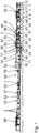
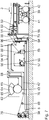
- Corrugating cardboard plant shown in its entirety is capable of producing an endless five-layer corrugated cardboard web 1 or five-layer corrugated cardboard sheets 2.
- the corrugated cardboard system is elongated. It essentially extends from a beginning (in Fig. 1 right) straight in a longitudinal direction or conveying direction 3.
- the corrugated cardboard plant comprises a first device 4 for producing a first web of corrugated cardboard 5 laminated on one side.
- a first cover web splicing device 6 and a first material web splicing device 7 are arranged upstream of the first device 4 for producing a first web of corrugated cardboard laminated on one side.
- the first cover web splicing device 6 comprises a first unwind unit for unrolling a finite first cover web from a first cover web roll 8 and a second unwind unit for unrolling a finite cover web from a second cover web roll 9.
- the finite first cover web and the finite second cover web are connected to one another in order to provide an endless first cover web 10 in the first cover web splicing device 6.
- the first material web splicing device 7, which forms a start of the corrugated board system, is designed in accordance with the first cover web splicing device 6. This comprises a third unwinding unit for unrolling a finite first material web from a first material web roll 11 and a fourth unwinding unit for unrolling a finite second material web from a second material web roll 12.
- the finite first material web and the finite second material web are to be provided an endless first material web 13 in the first material web splicing device 7 connected to one another.
- the endless first cover web 10 is fed via a first heating arrangement 14 to the first device 4 for producing a first web of corrugated cardboard 5 laminated on one side, while the endless first material web 13 is fed via a first deflection arrangement 14a to the first device 4 for producing a first web of corrugated board 5 laminated on one side .
- the first device 4 for producing a first corrugated cardboard web 5 laminated on one side comprises a rotatably mounted first corrugating roller 16 and a rotatably mounted second corrugating roller 17 for producing a corrugated endless first corrugated web 15 from the endless first material web 13 Passing through and corrugating the endless first material web 13 from a first nip 18. Together they form a first corrugation device.
- the first device 4 for producing a first sheet of corrugated board 5 laminated on one side has a first glue application device 19, which has a first glue metering roller 20, a first glue container 21 and a first glue application roller 22 comprises.
- the first glue application device 19 is arranged on a side of the first corrugating device facing away from the start of the corrugated board system.
- the first glue application roller 22 forms a first glue gap 23 with the first corrugated roller 16.
- the glue located in the first glue container 21 is applied via the first glue application roller 22 to the tips of the corrugation of the endless first corrugated web 15.
- the first glue metering roller 20 rests against the first glue application roller 22 and serves to form a uniform glue layer on the first glue application roller 22.
- the endless first cover web 10 is then joined together with the endless first corrugated web 15 provided with glue from the first glue container 21 in the first device 4 for producing a first web of corrugated cardboard 5 laminated on one side.
- the first device 4 for producing a first sheet of corrugated cardboard 5 laminated on one side has a first pressing module 24.
- the first pressing module 24 is Conveniently designed as a pressure belt module. It is arranged above the first corrugated roller 16.
- the first pressing module 24 has two first deflecting rollers 25 and an endless first pressing belt 26 which is guided around the two first deflecting rollers 25.
- the first corrugated roller 16 engages in a space between the two first deflecting rollers 25 from below in some areas, as a result of which the first pressure belt 26 is deflected by the first corrugating roller 16.
- the first pressure belt 26 presses against the endless first cover web 10, which in turn is pressed against the endless first corrugated web 15, which is provided with glue and rests on the first corrugated roller 16.
- the first device 4 for producing a first web of corrugated cardboard laminated on one side also comprises a first web tension influencing device 27, which is arranged upstream of the first pressing module 24 and is assigned to the endless first cover web 10. With the first Web tension influencing device 27 can thus influence the tension of the endless first cover web 10.
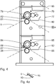
- the first device 4 for producing a first corrugated cardboard web 5 laminated on one side also comprises a first corrugating device changing device 28, which stores a previously inactive second corrugating device 29 for a change.
- the first corrugating device changing device 29 is arranged upstream of the first corrugating device with respect to the endless first material web 13. It comprises a third corrugating roller 30 and a fourth corrugating roller 31 for corrugating the endless first material web 13.
- the second corrugating device 29 has a different corrugation.
- the first corrugator changing device 28 is between an inactive parking position (see FIG Fig. 3 ) and an active corrugated position pivotable.
- the endless first material web 13 is expediently guided only through the corrugating device that is currently active and is guided past the inactive corrugating device. Alternatively, this is passed through both the inactive corrugating device and the active corrugating device.
- the endless first material web 13 is introduced via a first material web inlet 32 into the first device 4 for producing a first corrugated cardboard web 5 laminated on one side.
- the first material web entrance 32 faces the first material web splicing device 7 and thus the beginning of the corrugated board system.
- the first glue application device 19 is arranged on a side of the first fluting device facing away from the first web entrance 32.
- the endless first cover web 10 and the endless laminating web 50 occur at a point facing away from the first material web entrance 32 or at the beginning the side facing away from the corrugated cardboard system into the first pressing module 24 or in its pressing gap and leave this at a side facing the first material web entrance 32 or the beginning of the corrugated cardboard system.
- the first pressing module 24 has a first pressing inlet 33 and a first pressing outlet 34 arranged at a distance from it.
- the first pressing outlet 34 faces away from the first glue application device 19.
- the first pressing input 33 is arranged adjacent to the first glue application device 19.
- first web of corrugated cardboard laminated on one side it is fed to a bridge 36 of the corrugated cardboard system via a first upward transport device 35.
- first upward transport device 35 Between the first pressing module 24 and the bridge 36, the endless first corrugated sheet 15 of the first sheet of corrugated cardboard laminated on one side faces the beginning of the corrugated cardboard system.
- the endless first corrugated web 15 of the first corrugated cardboard web 5 laminated on one side faces upwards.
- the endless first cover sheet 10 of the first corrugated cardboard sheet 5 laminated on one side faces downwards.
- the first corrugated cardboard web 5 laminated on one side has been correspondingly deflected on the bridge 36 or the first upward transport device 35.
- the bridge 36 can also serve to temporarily store and buffer the first web of corrugated cardboard 5 laminated on one side.
- the corrugated cardboard plant also comprises a second device 37 for producing a second web of corrugated cardboard 38 laminated on one side.
- a second cover web splicing device 39 and a second material web splicing device 40 are arranged upstream of the second device 37 for producing a second web of corrugated cardboard laminated on one side.
- the second cover web splicing device 39 is designed like the first cover web splicing device 6. This comprises a fifth unwinding unit for unrolling a finite third cover web from a third cover web roll 41 and a sixth unwinding unit for unrolling a finite fourth cover web from a fourth cover web roll 42.
- the finite third cover sheet and fourth cover sheet are connected to one another in the second cover sheet splicing device 39 to provide an endless second cover sheet.
- the second material web splicing device 40 is designed like the first material web splicing device 7. This includes a seventh unwinding unit for unrolling a finite third material web from a third material web roll 43 and an eighth unwinding unit for unrolling a finite fourth material web from a fourth material web roll 44.
- the finite third material web and finite fourth material web are connected to one another in order to provide an endless second material web in the second material web splicing device 40.
- the endless second cover web is fed via a second heating arrangement 45 to the second device 37 for producing a second web of corrugated cardboard laminated on one side, while the endless second material web is fed via a second deflection arrangement to the second device 37 for producing a second web of corrugated board 38 laminated on one side.
- the second device 37 for producing a second web of corrugated cardboard laminated on one side is designed corresponding to the first device 4 for producing a first web of corrugated board 5 laminated on one side. She is also oriented analog. Reference is made to the previous description.
- a second pressing outlet of the second device 37 for producing a second web of corrugated cardboard laminated on one side is thus facing in the direction of the first pressing inlet 33 of the first device 4 for producing a first web of corrugated board 5 laminated on one side and thus facing the beginning of the corrugated board plant.
- the second web of corrugated cardboard laminated on one side is fed to the bridge 36 via a second upward transport device 46.
- an endless second corrugated sheet of the second sheet of corrugated cardboard laminated on one side faces upwards.
- an endless second cover sheet of the second sheet of corrugated cardboard laminated on one side faces downwards.
- the second corrugated cardboard web 38, laminated on one side has been correspondingly deflected on the bridge 36 or the second upward transport device 46. It is guided on the bridge 36 below the first web of corrugated cardboard 5 laminated on one side.
- the bridge 36 can also serve to temporarily store and buffer the second web of corrugated cardboard 38 laminated on one side.
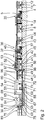
- the corrugated cardboard plant has a liner splicing device 47, which is designed like other splicing devices 6, 7, 39, 40.
- the liner web splicing device 47 is arranged adjacent to the second cover web splicing device 39 and comprises a ninth unwinding unit for unrolling a finite first lamination web from a first lamination web roll 48 and a tenth unwinding unit for unrolling a finite second laminating web from a second laminating web roll 49.
- the finite first laminating web and the finite second laminating web are used to provide an endless laminating web 50 in the laminating web splicing device 47 connected to each other.
- the endless laminating web 50 is single-ply.
- a brake arrangement 51 is arranged on the bridge 36 in a downstream end region, which comprises a first brake device 52 assigned to the first corrugated cardboard web 5 laminated on one side and a second brake device 53 assigned to the second corrugated board web 38 laminated on one side.
- the first braking device 52 is able to have a braking effect on the first corrugated cardboard web 5 laminated on one side.
- the second braking device 53 is able to have a braking effect on the second web of corrugated cardboard laminated on one side.
- the corrugated cardboard webs 5, 38 laminated on one side can thus be adapted to the endless laminating web 50.
- the brake arrangement 51 is arranged above the liner splicing device 47.
- a liner printing arrangement 54 is arranged in relation to the liner splice device 47.
- the liner printing arrangement 54 comprises a corona pretreatment device 55 which stands on a floor or substrate 56.
- the corona pretreatment device 55 comprises a corona carrier roller 57 and at least one electrode 58 arranged adjacent to it.
- the corona carrier roller 57 extends horizontally and perpendicular to the conveying direction 3 of the endless laminating web 50.
- the endless laminating web is around the corona carrier roller 57 50 led.
- the endless laminating web 50 runs through a gap that is formed or delimited by the corona carrier roller 57 and the at least one electrode 58.
- the corona pretreatment device 55 creates the endless laminating web 50 exposed to an electrical corona discharge, which leads to an oxidation of the surface, in particular on the pressure side. This results in higher dot gains when applying paint or printing later.
- the adhesion of a printing ink to the endless laminating web 50 can thus be improved.
- the laminating web printing arrangement 54 also has a precoating application device 59, which is arranged downstream of the corona pretreatment device 55 with respect to the endless laminating web 50 and stands on the floor 56.
- the precoating application device 59 is assigned to the endless laminating web 50 and is able to apply a flat precoating to an outside or pressure side of the endless laminating web 50.
- the pre-coating application device 59 advantageously uses at least one pre-coating roller 60 which extends horizontally and perpendicular to the conveying direction 3 of the endless laminating web 50.
- the at least one precoating roller 60 is preferably immersed in an applicatable precoating agent or is supplied with such.
- the laminating web printing arrangement 54 also has a precoating drying device 61 which is arranged downstream of the precoating application device 59 with respect to the endless laminating web 50 and dries the precoating or the endless laminating web 50 on the outside.
- the precoat drying device 61 extends horizontally. It is arranged above the corona pre-treatment device 55 and the pre-coating application device 59.
- the corona pretreatment device 55, the precoat applicator 59, and the precoat drying device 61 form a print preparation arrangement of the liner printing arrangement 54.
- the laminating web printing arrangement 54 furthermore comprises an inkjet printing device 62, which is arranged downstream of the pre-coating drying device 61 with respect to the endless laminating web 50.
- the inkjet printing device 62 is assigned to the endless laminating web 50 and is capable of printing at least one print on the outside of the endless laminating web 50 or the dried precoating.
- the pre-coating is thus located between the at least one print and the endless laminating web 50.
- the at least one print is advantageously a color print. It is located on the printing side of the endless laminating web 50.
- the inkjet printing device 62 comprises a central cylinder 63 which extends perpendicular to the conveying direction 3 of the endless laminating web 50 and horizontally. Furthermore, the inkjet printing device 62 has an inkjet printing bar 64 which has printing heads and which extends around the central cylinder 63 at a distance in some areas, forming a printing gap 65.
- the endless laminating web 50 is passed through the printing gap 65 for printing on the outside.
- the inkjet printing device 62 is arranged at least for the most part in a housing-like heat protection arrangement 66. During printing, it heats the endless laminating web 50.
- the laminating web printing arrangement 54 also has an infrared drying device 67, which is arranged downstream of the inkjet printing device 62 with respect to the endless laminating web 50 and is assigned to the endless laminating web 50.
- the infrared drying device 67 extends horizontally and dries the printed endless laminating web 50 or its at least one imprint using infrared radiation.
- the infrared drying device 67 is arranged below the inkjet printing device 62 or the heat protection arrangement 66 and adjacent to it.
- a hot air drying device 68 of the liner printing arrangement 54 is arranged in relation to the infrared drying device 67, which is assigned to the endless liner 50 and the already somewhat dried, printed endless liner 50 or its already somewhat dried imprint continues to dry with hot air.
- the hot air drying device 68 extends vertically and adjacent to the inkjet printing device 62 or the heat protection arrangement 66. It immediately follows the infrared drying device 67.
- the lamination web printing arrangement 54 advantageously has a multiplicity of deflection rollers in order to guide the endless lamination web 50 between the individual components of the lamination web printing arrangement 54.
- the corrugated cardboard plant Downstream of the hot-air drying device 68, the corrugated cardboard plant has a re-moistening device 69, which is assigned to the endless laminating web 50 and moistens it from below opposite the printing side.
- a smoothing roller is expediently used for this purpose.
- the remoistening device 69 is arranged downstream of a guide roller 70 which is in contact with the endless lamination web 50 and deflects it.
- the corrugated cardboard plant also comprises a guide arrangement 71 which extends horizontally below the liner web splicing device 67 and the liner web printing arrangement 54.
- the guide assembly 71 has a first guide device 72 for guiding the first corrugated cardboard web 5 laminated on one side and a second guide device 73 for guiding the second corrugated board web 38 laminated on one side.
- the first guide device 72 guides the first corrugated board web 5 laminated on one side above the second corrugated board web 38 laminated on one side and parallel to it in the guide arrangement 71.
- the corrugated cardboard webs 5, 38 laminated on one side are fed to the guide arrangement 71 by means of a downward feed device 74.
- the downward feed device 74 is arranged between the liner web splicing device 47 and the second cover web splicing device 39.
- the downward feed device 74 comprises / forms an alignment arrangement with two alignment devices 96 arranged between the lamination web splicing device 47 and the second cover web splicing device 39.
- Each one-sided laminated corrugated cardboard web 5, 38 is assigned its own alignment device 96, which is designed as a rotating frame and an upper roller 97 and lower roller 98 for Z-shaped wrapping through the respective one-sided laminated corrugated cardboard web 5, 38.
- the rollers 97, 98 of the respective aligning device 96 run parallel to one another and preferably at different heights. They are stored in the respective rotating frame.
- rollers 97, 98 of the respective aligning device 96 run horizontally and one above the other. A lateral deflection of the one-sided laminated corrugated cardboard web 5, 38 guided through there then does not occur.
- the rotating frames can each be pivoted independently of one another, for example by an actuator arrangement or a drive, to the one-sided laminated corrugated cardboard web 5 and / or 38 to deflect laterally.
- Each rotating frame is rotatable / pivotable in its entirety about a pivot point / pivot point, which is located between the upper roller 97 and the lower roller 98 of the respective rotating frame.
- a position correction of the respective one-sided laminated corrugated cardboard web 5, 38 is possible without applying an additional tensile force to one side of this web 5, 38.
- the actuator arrangement rotates the associated rotating frame as a whole in its vertical. In a deflected or rotated position of the rotating frame, its rollers 97, 98 run parallel to one another, but at an angle with respect to a horizontal or vertical.
- the corrugated cardboard webs 5, 38 laminated on one side are guided upwards again downstream to the laminating web printing arrangement 54 by means of a riser device 75.
- the guide arrangement 71 extends horizontally in the floor 56.
- a gluing unit 76 of the corrugated cardboard plant is arranged downstream of the remoistening device 69 and the riser device 75.
- the gluing unit 67 immediately follows the riser device 75.
- a horizontal distance between the lamination web printing arrangement 54 or the inkjet printing device 62 and the gluing unit 76 is extremely small, in particular less than 5 m.
- the endless laminating web 50 is already sufficiently heated by the active inkjet printing device 52.
- the gluing unit 76 has a first gluing device 77 with a first gluing roller 78 and a first squeezing roller 79, which rests on the first gluing roller 78 on the circumferential side.
- the first gluing roller 78 applies glue from a first glue pan 80 of the first gluing device 77 from above onto the upwardly facing first corrugated web 15 of the first corrugated cardboard web 5 laminated on one side.
- the first corrugated sheet 15 is thus arranged there above the associated endless first cover sheet 10.
- the first gluing device 77 also has a first pressure roller 81 which is arranged below the first gluing roller 78 and the first corrugated cardboard web 5 laminated on one side.
- the first pressure roller 81 and the first gluing roller 78 form a first pressure nip / glue gap 82 in which the first corrugated cardboard web 5 laminated on one side is pressed with its first corrugated web 15 against the first gluing roll 78.
- the first gluing roller 78 and the first squeezing roller 79 as well as the first glue pan 80 are arranged above the first corrugated cardboard web 5 laminated on one side.
- the first pressure roller 81 is arranged below the first web of corrugated cardboard 5 laminated on one side. There it deflects the first web of corrugated cardboard 5 laminated on one side.
- the gluing unit 76 has a second gluing device 83, which is designed like the first gluing device 77.
- the second gluing device 83 comprises a second gluing roller 84 and a second squeezing roller 85, which rests on the second gluing roller 84 on the circumferential side.
- the second gluing roller 84 applies glue from a second glue pan 86 of the second gluing device 86 from above onto the upwardly facing second corrugated web of the second corrugated cardboard web 38 laminated on one side.
- the second corrugated sheet is thus there above the associated endless second Cover sheet arranged.
- the second gluing device 83 also has a second pressure roller 87, which is arranged below the second gluing roller 84 and the second web of corrugated cardboard 38 laminated on one side.
- the second pressure roller 87 and the second gluing roller 84 form a second pressure nip / glue gap 88 in which the second corrugated cardboard web 38 laminated on one side is pressed with its second corrugated web against the second gluing roll 84.
- the second gluing roller 84 and the second squeezing roller 85 as well as the second glue pan 86 are arranged above the second corrugated cardboard web 38 laminated on one side.
- the second pressure roller 87 is arranged below the second web of corrugated cardboard 38, which is laminated on one side. There it deflects the second sheet of corrugated cardboard, which is laminated on one side.
- the endless lamination web 50 is guided through the gluing unit 76.
- the endless laminating web 50 thus runs in the gluing unit 76 above the first web of corrugated cardboard 5 laminated on one side and the second web of corrugated board 38 laminated on one side.
- the corrugated cardboard system Downstream of the gluing unit 76, the corrugated cardboard system has a pressing device 89 which comprises an endless upper pressing belt guided over upper guide rollers and a lower pressing belt guided over lower guide rollers.
- An upper chord of the lower press belt and a lower chord of the upper press belt run horizontally and parallel and adjacent to one another. They form a grouting section.
- the glued corrugated cardboard webs 5, 38, which are laminated on one side, and the endless laminating web 50 are guided through the pressing section.
- the first corrugated web 15 of the first corrugated cardboard web 5 laminated on one side and the second corrugated web of the second corrugated board web 38 laminated on one side are each directed upwards or arranged above.
- the endless corrugated cardboard web 1 is formed with setting or hardening of the glue, which is laminated on two sides and has a total of five layers.
- the corrugated cardboard plant Downstream of the pressing device 89, the corrugated cardboard plant has a short cross-cutting device 90, which comprises a knife cylinder and an opposing cylinder arranged below the same.
- the knife cylinder and counter cylinder are rotatably or rotatably mounted.
- the short transverse cutting device 90 is able to produce a cut which extends over the full width of the endless web of corrugated cardboard 1.
- the knife cylinder and counter cylinder are set in rotation in such a way that they interact with one another during the cutting process.
- the short transverse cutting device 90 is able to produce a cut with a certain length and a certain distance from a longitudinal edge of the endless corrugated cardboard web 1.
- counter-body elements of the counter-cylinder are selected or adjusted accordingly.
- the knife cylinder and the counter cylinder are set in rotation in such a way that a knife of the knife cylinder interacts with the counter body elements.
- the corrugated cardboard plant Downstream of the short transverse cutting device 90, the corrugated cardboard plant has a longitudinal cutting / creasing device 91 with two creasing units and two longitudinal cutting units arranged downstream of these.
- the slitting units are capable of cutting the endless web of corrugated cardboard 1 to form Cut partial corrugated cardboard sheets in the conveying direction 3.
- the scoring units are capable of scoring the endless web of corrugated cardboard 1 in order to facilitate later folding.
- a switch 92 of the corrugated cardboard system is provided downstream of the longitudinal cutting / scoring device 91 for dividing the partial webs of corrugated cardboard produced into two different levels.
- a cross-cutting device 93 Downstream of the switch 92 there is provided a cross-cutting device 93 with two partial cross-cutting devices arranged one above the other.
- Each partial cross-cutting device has two cross-cutting rollers, which can be driven in rotation, are arranged one above the other and extend perpendicular to the conveying direction 3, with cross-cutting knives extending radially outward for the complete cross-cutting of the respective partial web of corrugated cardboard while producing the corrugated cardboard sheets 2.
- a conveyor belt is arranged downstream of each partial cross-cutting device, on which the corrugated cardboard sheets 2 printed on the outside are guided to a respective stack tray 95.
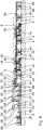
- the laminating web splicing device 47 is arranged at the very beginning of the corrugated board system, adjacent to the first material web splicing device 7.
- the endless laminating web 50 produced by the laminating web splicing device 47 is fed to the bridge 36 via a laminating web high transport device 94.
- the endless laminating web 50 is guided on the bridge 36 above the corrugated cardboard webs 5, 38 laminated on one side.
- first material web splicing device 7 For producing a first corrugated cardboard web 5 laminated on one side, the first cover web splicing device 6, the second material web splicing device 40, the second device 37 for producing a second corrugated board web 38 laminated on one side and the second Cover web splicing device 39 and the brake arrangement 51. It then enters the liner web printing arrangement 54 downstream of the brake arrangement 51.
- the corrugated cardboard webs 5, 38 laminated on one side are fed to the guide arrangement 71 via the downward feed device 74, which is located upstream of the laminating web printing arrangement 54 and downstream of the braking arrangement 51.
- the downward feeder 74 comprises / forms an alignment arrangement with two alignment devices 96 according to the previous embodiment.
- the guide arrangement 71 is arranged above the base 56. It extends horizontally and adjacent to it.
- the endless laminating web 50 is located in the gluing unit 76 and the pressing device 89 again above the corrugated cardboard webs 5, 38 laminated on one side.
- the corrugated cardboard plant has precisely one device for producing a web of corrugated cardboard laminated on one side. In this way, a corrugated cardboard sheet is produced in the corrugated cardboard plant, which has three layers.
Description
Die Erfindung betrifft eine Wellpappe-Anlage gemäß dem Oberbegriff des Anspruchs 1.The invention relates to a corrugated cardboard plant according to the preamble of
Wellpappe-Anlagen mit Druckanordnungen sind aus dem Stand der Technik durch offenkundige Vorbenutzung allgemein bekannt. Oftmals ist die Qualität der Bedruckung durch die Druckanordnungen nicht zufriedenstellend.Corrugated cardboard systems with printing arrangements are generally known from the prior art due to prior public use. The quality of the printing by the printing arrangements is often unsatisfactory.
Aus der gattungsgemäßen
Die
Die
Aus der
Die
Der Erfindung liegt die Aufgabe zugrunde, eine Wellpappe-Anlage mit einer Druckanordnung zu schaffen, die einen vergleichsweise kleinen Platzbedarf erfordert. Ferner soll die Druckqualität bzw. Wellpappequalität besonders hoch sein.The invention is based on the object of creating a corrugated cardboard system with a printing arrangement which requires a comparatively small amount of space. Furthermore, the print quality or corrugated board quality should be particularly high.
Diese Aufgabe wird erfindungsgemäß durch die in dem unabhängigen Anspruch 1 angegebenen Merkmale gelöst.This object is achieved according to the invention by the features specified in
Der Kern bei der erfindungsgemäßen Wellpappe-Anlage liegt darin, dass mittels einer Kaschierbahn-Druckanordnung die Kaschierbahn, insbesondere zeitlich und/oder örtlich, vor der Bildung einer zweiseitig kaschierten Wellpappebahn in der Vorrichtung zum Herstellen einer zweiseitig kaschierten Wellpappebahn, also vor Verbindung mit einer einseitig kaschierten Wellpappebahn, bedruckt wird. Im Betrieb bedruckt die Kaschierbahn-Druckanordnung die geförderte, insbesondere noch ungebundene, Kaschierbahn auf einer äußeren Druckseite. Die Kaschierbahn ist bzw. bleibt eine glatte, ungewellte Bahn. Die zweiseitig kaschierte Wellpappebahn ist mindestens dreilagig, vorzugsweise dreilagig, fünflagig oder siebenlagig.The core of the corrugated cardboard system according to the invention is that, by means of a laminating web printing arrangement, the laminating web, in particular temporally and / or locally, before the formation of a double-sided laminated corrugated board web in the device for producing a double-sided laminated corrugated board web, i.e. before connection to a one-sided laminated corrugated cardboard web, is printed. During operation, the laminating web printing arrangement prints the conveyed, in particular still unbound, laminating web on an outer print side. The lamination web is or remains a smooth, non-corrugated web. The web of corrugated cardboard laminated on both sides has at least three layers, preferably three, five or seven layers.
Die mindestens eine einseitig kaschierte Wellpappebahn hat benachbart zu der Vorrichtung zum Herstellen einer zweiseitig kaschierten Wellpappebahn und insbesondere auch in dieser eine jeweilige nach oben gerichtete Wellung. Die Wellbahn befindet sich so dort oberhalb der zugehörigen/zugeordneten Deckbahn der jeweiligen einseitig kaschierten Wellpappebahn.The at least one web of corrugated cardboard laminated on one side has a respective upwardly directed corrugation adjacent to the device for producing a double-sided laminated corrugated cardboard web and in particular also in this. The corrugated sheet is located there above the associated / assigned cover sheet of the respective single-sided laminated sheet of corrugated cardboard.
Die Vorrichtung zum Herstellen einer zweiseitig kaschierten Wellpappebahn kaschiert die Kaschierbahn von oben auf die benachbarte einseitig kaschierte Wellpappebahn auf.The device for producing a double-sided laminated corrugated cardboard web laminates the laminating web from above onto the adjacent one-sided laminated corrugated cardboard web.
Die Kaschierbahn-Druckanordnung ist vorteilhafterweise als Digital-Druckanordnung, insbesondere Inkjet-Druckanordnung, ausgebildet. Sie ist vorzugsweise nachrüstbar. Andere bekannte Druckanordnungen sind alternativ einsetzbar. Die Kaschierbahn-Druckanordnung ist insbesondere imstande, mindestens einen Buchstaben, eine Ziffer, ein anderes Zeichen, eine Grafik und/oder ein Foto auf die Kaschierbahn aufzudrucken. Dafür wird günstigerweise Farbe oder Tinte herangezogen. Es ist von Vorteil, wenn die Kaschierbahn-Druckanordnung imstande ist, mehrfarbig zu drucken.The laminating web printing arrangement is advantageously designed as a digital printing arrangement, in particular an inkjet printing arrangement. It can preferably be retrofitted. Other known pressure arrangements can alternatively be used. The laminating web printing arrangement is in particular capable of printing at least one letter, a number, another character, a graphic and / or a photo onto the laminating web. For that will favorably color or ink is used. It is advantageous if the liner printing arrangement is capable of printing in multiple colors.
Die Kaschierbahn-Druckanordnung weist günstigerweise mehrere in der Querrichtung in der Kaschierbahn kaskadiert angeordnete Druckköpfe auf. Vorzugsweise hat die Kaschierbahn-Druckanordnung mehrere hintereinander angeordnete Druckkopfreihen. Es ist von Vorteil, wenn die zu bedruckende Kaschierbahn in der Kaschierbahn-Druckanordnung beim Bedrucken über einen Druckzylinder bzw. Zentralzylinder geführt ist. Der Druckzylinder erstreckt sich vorzugsweise horizontal und senkrecht zu einer Förderrichtung der Kaschierbahn.The laminating web printing arrangement advantageously has a plurality of print heads cascaded in the transverse direction in the laminating web. The laminating web printing arrangement preferably has several rows of print heads arranged one behind the other. It is advantageous if the liner web to be printed in the liner web printing arrangement is guided over a printing cylinder or central cylinder during printing. The printing cylinder preferably extends horizontally and perpendicular to a conveying direction of the laminating web.
Günstigerweise gibt mindestens eine Deckbahn-Abgabevorrichtung die jeweilige Deckbahn ab. Es ist zweckmäßig, wenn die mindestens eine Deckbahn-Abgabevorrichtung als Splicevorrichtung zum Bereitstellen einer jeweiligen endlosen Deckbahn ausgebildet ist.At least one cover sheet dispensing device expediently dispenses the respective cover sheet. It is expedient if the at least one cover web dispensing device is designed as a splice device for providing a respective endless cover web.
Vorzugsweise gibt mindestens eine Materialbahn-Abgabevorrichtung die jeweilige Materialbahn ab. Es ist von Vorteil, wenn die mindestens eine Materialbahn-Abgabevorrichtung als Splicevorrichtung zum Bereitstellen einer jeweiligen endlosen Materialbahn ausgebildet ist.At least one material web dispensing device preferably dispenses the respective material web. It is advantageous if the at least one material web dispensing device is designed as a splicing device for providing a respective endless material web.
Die Kaschierbahn-Abgabevorrichtung ist bevorzugt als Splicevorrichtung zum Bereitstellen einer endlosen Kaschierbahn ausgebildet.The laminating web dispensing device is preferably designed as a splicing device for providing an endless laminating web.
Günstigerweise verbindet die Vorrichtung zum Herstellen einer zweiseitig kaschierten Wellpappebahn die mindestens eine einseitig kaschierte Wellpappebahn mit der, insbesondere bedruckten, Kaschierbahn. Die Vorrichtung zum Herstellen einer zweiseitig kaschierten Wellpappebahn weist vorzugsweise mindestens einen Verpressspalt bzw. mindestens eine Verpressstrecke auf, durch den/die die mindestens eine einseitig kaschierte Wellpappebahn und die Kaschierbahn geführt sind und aneinander gepresst werden. Zwischen den Bahnen befindet sich vorzugsweise Leim zur leimenden Verbindung derselben. Der mindestens eine Verpressspalt bzw. die mindestens eine Verpressstrecke ist günstigerweise durch mindestens zwei paarweise angeordnete, insbesondere antreibbare, Verpresswalzen oder Verpressgurte gebildet bzw. begrenzt. Die Verpressgurte sind vorzugsweise endlos.The device for producing a corrugated cardboard web laminated on both sides advantageously connects the at least one corrugated cardboard web laminated on one side to the, in particular printed, laminating web. The device for producing a double-sided laminated corrugated cardboard web has preferably at least one pressing gap or at least one pressing section through which the at least one web of corrugated cardboard laminated on one side and the laminating web are guided and pressed together. Between the strips there is preferably glue for the gluing connection of the same. The at least one compression gap or the at least one compression section is advantageously formed or delimited by at least two, in particular drivable, compression rollers or compression belts arranged in pairs. The compression belts are preferably endless.
Jede Riffeleinrichtung ist günstigerweise durch zwei drehbar gelagerte Riffelwalzen gebildet. Die Riffelwalzen bilden zum Durchführen und Riffeln der jeweiligen Materialbahn unter Bildung einer Wellbahn einen Walzenspalt bzw. Riffelspalt aus.Each corrugating device is advantageously formed by two rotatably mounted corrugating rollers. The corrugated rollers form a roller gap or corrugated gap for guiding through and corrugating the respective material web to form a corrugated web.
Die Anpresseinrichtung presst günstigerweise die jeweilige Deckbahn gegen die Wellbahn, die vorzugsweise an der benachbarten Riffelwalze anliegt.The pressing device expediently presses the respective cover sheet against the corrugated sheet, which preferably rests against the adjacent corrugated roller.
Es ist von Vorteil, wenn die Anpresseinrichtung als Anpressbandmodul ausgeführt ist. Die einseitig kaschierte Wellpappebahn verlässt vorzugsweise die jeweilige Anpresseinrichtung über einen jeweiligen Anpressausgang, der der Vorrichtung zum Herstellen einer zweiseitig kaschierten Wellpappebahn abgewandt ist. Der Anpresseingang und -Ausgang der jeweiligen Anpresseinrichtung sind günstigerweise zueinander beabstandet angeordnet.It is advantageous if the pressing device is designed as a pressing belt module. The web of corrugated cardboard laminated on one side preferably leaves the respective pressing device via a respective pressing outlet which faces away from the device for producing a web of corrugated cardboard laminated on both sides. The pressing input and output of the respective pressing device are advantageously arranged at a distance from one another.
Die mindestens eine Umlenkanordnung weist günstigerweise mindestens eine Umlenkwalze bzw. -stange auf. Die mindestens eine Umlenkwalze bzw. -stange erstreckt sich bevorzugt senkrecht zu der zugehörigen einseitig kaschierten Wellpappebahn bzw. zu deren Förderrichtung und horizontal. Die mindestens eine Umlenkanordnung ist beispielsweise Bestandteil der mindestens einen Vorrichtung zum Herstellen einer einseitig kaschierten Wellpappebahn und/oder einer Brücke. Alternativ ist diese separat ausgeführt und beispielsweise zwischen der mindestens einen Vorrichtung zum Herstellen einer einseitig kaschierten Wellpappebahn und der Brücke angeordnet.The at least one deflection arrangement advantageously has at least one deflection roller or rod. The at least one deflection roller or rod extends preferably perpendicular to the associated web of corrugated cardboard laminated on one side or to its conveying direction and horizontally. The at least one deflection arrangement is, for example, part of the at least one device for producing a web of corrugated cardboard laminated on one side and / or a bridge. Alternatively, this is implemented separately and arranged, for example, between the at least one device for producing a web of corrugated cardboard laminated on one side and the bridge.
Die hier verwendeten Ausdrücke "vorgeordnet", "nachgeordnet", "stromaufwärts", "stromabwärts", "hintereinander" oder dergleichen beziehen sich insbesondere auf die Förderrichtung der jeweiligen geförderten Bahn.The expressions “upstream”, “downstream”, “upstream”, “downstream”, “behind each other” or the like used here relate in particular to the conveying direction of the respective conveyed web.
Ein nicht erfindungsgemäßes Verfahren zum Herstellen von Wellpappe umfasst vorzugsweise den Schritt
- Auftragen von Leim mittels eines Leimwerks auf freie Spitzen von mindestens einer einseitig kaschierten Wellpappebahn zur leimenden Verbindung derselben mit einer weiteren Bahn zur Bildung einer zweiseitig kaschierten Wellpappebahn, wobei der Leim Verarbeitungstemperaturen von unter 70 °C erlaubt, die günstigerweise zumindest an der mindestens einen einseitig kaschierten Wellpappebahn und/oder der Kaschierbahn vorliegen.
- Application of glue by means of a gluing unit to free tips of at least one single-sided laminated corrugated cardboard web for gluing connection of the same with a further web to form a double-sided laminated corrugated cardboard web, the glue allowing processing temperatures of below 70 ° C, which are advantageously at least one laminated on at least one Corrugated cardboard web and / or the laminating web are present.
Die Verarbeitungstemperaturen des Leims von unter 70 °C führen dazu, dass besonders wenig Energie zur Herstellung der Wellpappe benötigt wird. Ferner werden die zu beleimenden bzw. miteinander zu verbindenden Bahnen geschont. Der Leim hat eine vergleichsweise niedrige Abbindetemperatur bzw. Aushärtetemperatur.The processing temperatures of the glue of below 70 ° C mean that particularly little energy is required to manufacture the corrugated cardboard. Furthermore, the webs to be glued or connected to one another are protected. The glue has a comparatively low setting temperature or curing temperature.
Weitere vorteilhafte Ausgestaltungen der Erfindung sind in den Unteransprüchen angegeben.Further advantageous configurations of the invention are specified in the subclaims.
Die mindestens eine Leimauftragseinrichtung gemäß dem Unteranspruch 2 hat vorzugsweise jeweils eine Leimdosierwalze, einen Leimbehälter und eine Leimauftragswalze. Zum Durchführen und Beleimen der jeweiligen Wellbahn bildet die entsprechende Leimauftragswalze mit einer Riffelwalze vorzugsweise einen Leimspalt auf. Der sich in dem Leimbehälter befindende Leim wird günstigerweise über die Leimauftragswalze auf Spitzen der Wellung der Wellbahn aufgetragen. Die Leimdosierwalze liegt vorzugsweise gegen die benachbarte Leimauftragswalze an und dient zum Ausbilden einer gleichmäßigen Leimschicht auf der Leimauftragswalze. Das Leimwerk gemäß dem Unteranspruch 3 trägt günstigerweise Leim von oben auf Spitzen der Wellung der mindestens einen einseitig kaschierten Wellpappebahn auf. Günstigerweise wird dieses Auftragen durch Schwerkraft unterstützt.The at least one glue application device according to
Der in dem Leimwerk eingesetzte Leim erlaubt bevorzugt Verarbeitungstemperaturen von unter 70° C. Dieses Leimwerk hat einen besonders niedrigen Energiebedarf. Wellpappe ist so äußerst wirtschaftlich herstellbar. Ferner wird so bevorzugt besonders wenig Feuchtigkeit in die mindestens eine einseitig kaschierte Wellpappebahn eingebracht, was eine plane Oberseite ergibt und eine äußerst kurze Vorrichtung zum Herstellen einer zweiseitig kaschierten Wellpappebahn erlaubt.The glue used in the glue unit preferably allows processing temperatures below 70 ° C. This glue unit has a particularly low energy requirement. Corrugated cardboard can thus be produced extremely economically. Furthermore, particularly little moisture is preferably introduced into the at least one web of corrugated cardboard laminated on one side, which results in a flat upper side and allows an extremely short device for producing a corrugated cardboard web laminated on both sides.
Der Leim hat eine vergleichsweise niedrige Abbindetemperatur bzw. Aushärtetemperatur.The glue has a comparatively low setting temperature or curing temperature.
Insbesondere erfolgt eine Abbindung bzw. Aushärtung des Leims beim Auftragen desselben auf die mindestens eine einseitig kaschierte Wellpappebahn bzw. unmittelbar danach, deren Leim-Aufnahmegebiet vorzugsweise eine Temperatur aufweist, die zur Abbindung, Aushärtung bzw. Trocknung des Leims ausreichend ist. Bereiche des Leims bzw. von Leimlinien erfahren dabei sowohl beim Leimauftrag als auch danach günstigerweise Temperaturen von unter 70 °C. Die Verarbeitungstemperaturen des Leims liegen günstigerweise an der mindestens einen einseitig kaschierten Wellpappebahn vor.In particular, the glue is set or hardened when it is applied to the at least one web of corrugated cardboard laminated on one side or immediately thereafter, the glue receiving area of which is preferably at a temperature that is sufficient for setting, hardening or drying the glue. Areas of the glue or glue lines, both during the application of glue and afterwards, beneficially experience temperatures below 70 ° C. The processing temperatures of the glue are favorably present on the at least one web of corrugated cardboard laminated on one side.
Die mindestens eine Beleimungswalze gemäß dem Unteranspruch 4 ist günstigerweise oberhalb der jeweiligen zu beleimenden einseitig kaschierten Wellpappebahn angeordnet. Es ist zweckmäßig, wenn das Leimwerk ferner mindestens ein Leimbad aufweist, in das die mindestens eine Beleimungswalze eingetaucht ist bzw. diese mit Leim versorgt. Günstigerweise hat das Leimwerk mindestens eine Dosierwalze, die an der mindestens einen Beleimungswalze zum Ausbilden eines gleichmäßigen Leimfilms auf der Beleimungswalze umfangsseitig anliegt. Eine Befüllung des Leimbads erfolgt vorzugsweise von oben.The at least one gluing roller according to
Das Leimwerk ist günstigerweise der Kaschierbahn-Druckanordnung nachgeordnet und, insbesondere unmittelbar, benachbart zu der Kaschierbahn-Druckanordnung angeordnet, insbesondere derart, dass die Kaschierbahn-Druckanordnung die Kaschierbahn derart erwärmt, dass der durch das Leimwerk aufgebrachte Leim abbindet.The gluing unit is favorably arranged downstream of the laminating web printing arrangement and, in particular, arranged directly adjacent to the laminating web printing arrangement, in particular such that the laminating web printing arrangement heats the laminating web in such a way that the glue applied by the gluing unit sets.
Es ist von Vorteil, wenn die Kaschierbahn-Druckanordnung benachbart zu dem Leimwerk angeordnet ist. Eine separate Vorheizanordnung zum Vorheizen der mindestens einen einseitig kaschierten Wellpappebahn und/oder der Kaschierbahn, insbesondere unmittelbar stromaufwärts zu der Vorrichtung zum Herstellen einer zweiseitig kaschierten Wellpappebahn bzw. zu dem Leimwerk, ist so hinfällig. Dies ist insbesondere darauf zurückzuführen, dass zwischen der Bedruckung durch die mindestens eine Kaschierbahn-Druckvorrichtung und der Vorrichtung zum Herstellen einer zweiseitig kaschierten Wellpappebahn eine besonders kurze Strecke vorliegt. Günstigerweise ist ein Abstand zwischen der Kaschierbahn-Druckanordnung bzw. der mindestens einen Kaschierbahn-Druckvorrichtung der Kaschierbahn-Druckanordnung und dem Leimwerk kleiner als 5 m. Die Kaschierbahn-Druckanordnung hat beispielsweise mindestens ein eigenes Heizelement zum Erwärmen der Kaschierbahn. Beispielsweise erfolgt eine entsprechende Erwärmung der Kaschierbahn durch mindestens eine der Kaschierbahn zugeordnete Bedruckungs-Trocknungsvorrichtung der Kaschierbahn-Druckanordnung.It is advantageous if the laminating web printing arrangement is arranged adjacent to the gluing unit. A separate preheating arrangement for preheating the at least one web of corrugated cardboard laminated on one side and / or the laminating web, in particular immediately upstream of the device for producing a web of corrugated board laminated on both sides or to the gluing unit, is thus obsolete. This is due in particular to the fact that there is a particularly short distance between the printing by the at least one lamination web printing device and the device for producing a corrugated cardboard web laminated on both sides. A distance between the laminating web printing arrangement or the at least one laminating web printing device of the laminating web printing arrangement and the gluing unit is advantageously less than 5 m. The laminating web printing arrangement has, for example, at least one heating element of its own for heating the laminating web. For example, the liner web is correspondingly heated by at least one printing / drying device of the liner web printing arrangement assigned to the liner web.
Die Kaschierbahn-Druckanordnung erwärmt vorzugsweise die Kaschierbahn derart, dass diese in der Vorrichtung zum Herstellen einer zweiseitig kaschierten Wellpappebahn mit der benachbarten einseitig kaschierten Wellpappebahn leimend verbindbar ist. Diese Wellpappe-Anlage hat wieder einen besonders niedrigen Energiebedarf. Wellpappe ist so äußerst wirtschaftlich herstellbar. Günstigerweise erwärmt die Kaschierbahn-Druckanordnung die Kaschierbahn beim Bedrucken derselben bzw. bei einer Drucktrocknung zumindest bereichsweise auf maximal 120 °C, bevorzugter auf 50 °C bis 70 °C.The laminating web printing arrangement preferably heats the laminating web in such a way that it can be glued in the device for producing a double-sided laminated corrugated cardboard web with the adjacent one-sided laminated corrugated board web. This corrugated cardboard plant again has a particularly low energy requirement. Corrugated cardboard can thus be produced extremely economically. The liner web printing arrangement expediently heats the liner web to a maximum of 120 ° C., more preferably to 50 ° C. to 70 ° C., at least in some areas when it is printed on or when it is pressure-dried.
Die Wellpappe-Anlage gemäß dem Unteranspruch 5 hat zumindest bei der Kaschierbahn-Druckanordnung eine besonders niedrige Höhe. Es ist von Vorteil, wenn die Führungsanordnung benachbart zu einem die Wellpappe-Anlage tragenden Boden verläuft. Die Führungsanordnung ist beispielsweise oberhalb des Bodens oder in dem Boden angeordnet, was zu einer oberirdischen bzw. unterirdischen Führung der mindestens einen einseitig kaschierten Wellpappebahn führt. Die mindestens eine einseitig kaschierte Wellpappebahn passiert vorzugsweise die Kaschierbahn-Druckanordnung in der Führungsanordnung. Es ist zweckmäßig, wenn die Führungsanordnung mindestens eine Leitwalze und/oder ein Leitband zur Führung der mindestens einen einseitig kaschierten Wellpappebahn umfasst.The corrugated cardboard plant according to
Die mindestens eine Kaschierbahn-Druckvorrichtung weist günstigerweise einen Zentralzylinder und einen Druckriegel auf, der unter Bildung eines Druckspalts zur Hindurchführung der Kaschierbahn benachbart zu dem Zentralzylinder angeordnet ist. Diese mindestens eine Kaschierbahn-Druckvorrichtung ermöglicht eine äußerst hohe Druckqualität. Außerdem ist so eine äußerst wirtschaftliche Bedruckung möglich.The at least one lamination web printing device advantageously has a central cylinder and a pressure bar which is arranged adjacent to the central cylinder, forming a pressure gap for the lamination web to pass through. This at least one liner printing device enables extremely high print quality. In addition, extremely economical printing is possible.
Die Wellpappe-Anlage umfasst bevorzugt eine der Vorrichtung zum Herstellen einer zweiseitig kaschierten Wellpappebahn vorgeordnete Ausrichtanordnung zum Ausrichten der mindestens einen kaschierten Wellpappebahn und der Kaschierbahn nacheinander.The corrugated cardboard system preferably comprises an alignment arrangement arranged upstream of the device for producing a corrugated cardboard web laminated on both sides for aligning the at least one laminated corrugated cardboard web and the laminating web one after the other.
Diese Wellpappe-Anlage hat wieder eine besonders hohe Wellpappequalität zufolge. Insbesondere ist so eine besonders gute Anpassung bzw. Angleichung der mindestens einen einseitig kaschierten Wellpappebahn und der Kaschierbahn nacheinander möglich. Insbesondere ist die mindestens eine einseitig kaschierte Wellpappebahn und/oder die Kaschierbahn seitlich auslenkbar. Die Ausrichtanordnung hat dazu vorzugsweise mindestens eine verlagerbare Ausrichtrolle bzw. -walze, um die die mindestens eine auszurichtende Bahn geführt ist. Es ist zweckmäßig, wenn die Ausrichtanordnung mindestens einen verdrehbaren bzw. verschwenkbaren Drehrahmen, insbesondere mit mindestens zwei Bahn-Führungswalzen, und/oder mindestens eine Kamberrolle/Schwenkwalze zum Ausrichten der Kaschierbahn und/oder der mindestens einen einseitig kaschierten Wellpappebahn umfasst. Die mindestens eine Kamberrolle/Schwenkwalze schwenkt sich dabei vorzugsweise in einer horizontalen Ebene und günstigerweise um ihren, insbesondere axialen, Mittelpunkt. Beispielsweise liegt ein Schwerpunkt stromaufwärts in einer Trocknungsvorrichtung.This corrugated cardboard plant again has a particularly high quality of corrugated cardboard. In particular, a particularly good adaptation or adjustment of the at least one web of corrugated cardboard laminated on one side and the laminating web is possible one after the other. In particular, the at least one web of corrugated cardboard laminated on one side and / or the laminating web can be deflected laterally. For this purpose, the alignment arrangement preferably has at least one displaceable alignment roller or roller around which the at least one web to be aligned is guided. It is useful if the alignment arrangement at least one rotatable or pivotable rotating frame, in particular with at least two web guide rollers, and / or at least one cam roller / pivot roller for aligning the lamination web and / or which comprises at least one web of corrugated cardboard laminated on one side. The at least one cam roller / pivot roller preferably pivots in a horizontal plane and advantageously about its, in particular axial, center. For example, a center of gravity is upstream in a drying device.
Die Ausgestaltung gemäß dem Unteranspruch 6 ermöglicht eine äußerst kurze Transportstrecke der Kaschierbahn zwischen der Kaschierbahn-Abgabevorrichtung und der Kaschierbahn-Druckanordnung.The embodiment according to
Günstigerweise bildet gemäß dem Unteranspruch 7 die Kaschierbahn-Abgabevorrichtung den Anfang der Wellpappe-Anlage. Es ist von Vorteil, wenn eine Bedruckung auf Brückenniveau erfolgt.Advantageously, according to
Die Vorrichtung zum Herstellen einer zweiseitig kaschierten Wellpappenbahn hat vorzugsweise eine Länge, die kleiner als 15 m ist.The device for producing a double-sided laminated corrugated cardboard web preferably has a length which is less than 15 m.
Nachfolgend werden unter Bezugnahme auf die beigefügte Zeichnung zwei bevorzugte Ausführungsformen der Erfindung beispielhaft beschrieben. Dabei zeigen:
- Fig. 1
- eine schematische Seitenansicht einer erfindungsgemäßen Wellpappe-Anlage,
- Fig. 2
- einen vergrößerten Ausschnitt aus
Fig. 1 , der die Vorrichtung zum Herstellen einer zweiseitig kaschierten Wellpappebahn und den dieser vorgeordneten Teil der Wellpappe-Anlage gemäßFig. 1 veranschaulicht, - Fig. 3
- eine Seitenansicht einer Vorrichtung zum Herstellen einer einseitig kaschierten Wellpappebahn der in
Fig. 1 ,2 gezeigten Wellpappe-Anlage, - Fig. 3a
- einen vergrößerten Ausschnitt, der die Orientierung der einseitig kaschierten Wellpappebahn nach deren Bildung nach der Anpresseinrichtung zeigt,
- Fig. 4
- eine Seitenansicht eines Leimwerks der in
Fig. 1 ,2 gezeigten Wellpappe-Anlage, - Fig. 4a
- einen vergrößerten Ausschnitt, der die Orientierung einer einseitig kaschierten Wellpappebahn benachbart stromaufwärts zu dem Leimwerk zeigt,
- Fig. 5
- eine Seitenansicht einer erfindungsgemäßen Wellpappe-Anlage gemäß einer zweiten Ausführungsform,
- Fig. 6
- einen vergrößerten Ausschnitt aus
Fig. 5 , der die Vorrichtung zum Herstellen einer zweiseitig kaschierten Wellpappebahn und den vorgeordneten Teil der Wellpappe-Anlage zeigt, - Fig. 7
- einen vergrößerten Ausschnitt aus
Fig. 5 , und - Fig. 8
- einen vergrößerten Ausschnitt aus
Fig. 1 .
- Fig. 1
- a schematic side view of a corrugated cardboard plant according to the invention,
- Fig. 2
- an enlarged section
Fig. 1 , the device for producing a double-sided laminated corrugated cardboard web and the according to this upstream part of the corrugated board plantFig. 1 illustrates - Fig. 3
- a side view of a device for producing a single-sided laminated corrugated cardboard web of the in
Fig. 1 ,2 shown corrugated board plant, - Fig. 3a
- an enlarged section showing the orientation of the one-sided laminated corrugated cardboard web after its formation after the pressing device,
- Fig. 4
- a side view of a gluing unit in
Fig. 1 ,2 shown corrugated board plant, - Figure 4a
- an enlarged section showing the orientation of a single-sided laminated corrugated cardboard web adjacent upstream of the gluing unit,
- Fig. 5
- a side view of a corrugated cardboard plant according to the invention according to a second embodiment,
- Fig. 6
- an enlarged section
Fig. 5 , which shows the device for producing a double-sided laminated corrugated cardboard web and the upstream part of the corrugated cardboard plant, - Fig. 7
- an enlarged section
Fig. 5 , and - Fig. 8
- an enlarged section
Fig. 1 .
Eine in
Die Wellpappe-Anlage umfasst eine erste Vorrichtung 4 zum Herstellen einer einseitig kaschierten ersten Wellpappebahn 5.The corrugated cardboard plant comprises a
Der ersten Vorrichtung 4 zum Herstellen einer einseitig kaschierten ersten Wellpappebahn 5 sind eine erste Deckbahn-Splicevorrichtung 6 und eine erste Materialbahn-Splicevorrichtung 7 vorgeordnet.A first cover
Die erste Deckbahn-Splicevorrichtung 6 umfasst zum Abrollen einer endlichen ersten Deckbahn von einer ersten Deckbahnrolle 8 eine erste Abrolleinheit und zum Abrollen einer endlichen Deckbahn von einer zweiten Deckbahnrolle 9 eine zweite Abrolleinheit. Die endliche erste Deckbahn und die endliche zweite Deckbahn werden zum Bereitstellen einer endlosen ersten Deckbahn 10 in der ersten Deckbahn-Splicevorrichtung 6 miteinander verbunden.The first cover
Die erste Materialbahn-Splicevorrichtung 7, die einen Anfang der Wellpappe-Anlage bildet, ist entsprechend der ersten Deckbahn-Splicevorrichtung 6 ausgebildet. Diese umfasst zum Abrollen einer endlichen ersten Materialbahn von einer ersten Materialbahnrolle 11 eine dritte Abrolleinheit und zum Abrollen einer endlichen zweiten Materialbahn von einer zweiten Materialbahnrolle 12 eine vierte Abrolleinheit. Die endliche erste Materialbahn und die endliche zweite Materialbahn werden zum Bereitstellen einer endlosen ersten Materialbahn 13 in der ersten Materialbahn-Splicevorrichtung 7 miteinander verbunden.The first material
Die endlose erste Deckbahn 10 wird über eine erste Heizanordnung 14 der ersten Vorrichtung 4 zum Herstellen einer einseitig kaschierten ersten Wellpappebahn 5 zugeführt, während die endlose erste Materialbahn 13 über eine erste Umlenkanordnung 14a der ersten Vorrichtung 4 zum Herstellen einer einseitig kaschierten ersten Wellpappebahn 5 zugeführt wird.The endless
Die erste Vorrichtung 4 zum Herstellen einer einseitig kaschierten ersten Wellpappebahn 5 umfasst zum Erzeugen einer eine Wellung aufweisenden endlosen ersten Wellbahn 15 aus der endlosen ersten Materialbahn 13 eine drehbar gelagerte erste Riffelwalze 16 und eine drehbar gelagerte zweite Riffelwalze 17. Die Riffelwalzen 16, 17 bilden zum Durchführen und Riffeln der endlosen ersten Materialbahn 13 einen ersten Walzenspalt 18 aus. Sie bilden zusammen eine erste Riffeleinrichtung.The
Zum Verbinden der endlosen ersten Wellbahn 15 mit der endlosen ersten Deckbahn 10 zu der einseitig kaschierten ersten Wellpappebahn 5 weist die erste Vorrichtung 4 zum Herstellen einer einseitig kaschierten ersten Wellpappebahn 5 eine erste Leimauftragseinrichtung 19 auf, die eine erste Leimdosierwalze 20, einen ersten Leimbehälter 21 und eine erste Leimauftragswalze 22 umfasst. Die erste Leimauftragseinrichtung 19 ist an einer dem Anfang der Wellpappe-Anlage abgewandten Seite der ersten Riffeleinrichtung angeordnet. Zum Durchführen und Beleimen der endlosen ersten Wellbahn 15 bildet die erste Leimauftragswalze 22 mit der ersten Riffelwalze 16 einen ersten Leimspalt 23 aus. Der sich in dem ersten Leimbehälter 21 befindende Leim wird über die erste Leimauftragswalze 22 auf Spitzen der Wellung der endlosen ersten Wellbahn 15 aufgetragen. Die erste Leimdosierwalze 20 liegt gegen die erste Leimauftragswalze 22 an und dient zum Ausbilden einer gleichmäßigen Leimschicht auf der ersten Leimauftragswalze 22.To connect the endless first
Die endlose erste Deckbahn 10 wird anschließend mit der mit Leim aus dem ersten Leimbehälter 21 versehenen endlosen ersten Wellbahn 15 in der ersten Vorrichtung 4 zum Herstellen einer einseitig kaschierten ersten Wellpappebahn 5 zusammengefügt.The endless
Zum Anpressen der endlosen ersten Deckbahn 10 gegen die mit Leim versehene endlose erste Wellbahn 15, die wiederum bereichsweise an der ersten Riffelwalze 16 anliegt, hat die erste Vorrichtung 4 zum Herstellen einer einseitig kaschierten ersten Wellpappebahn 5 ein erstes Anpressmodul 24. Das erste Anpressmodul 24 ist günstigerweise als Anpressbandmodul ausgeführt. Es ist oberhalb der ersten Riffelwalze 16 angeordnet. Das erste Anpressmodul 24 hat zwei erste Umlenkwalzen 25 und ein endloses erstes Anpressband 26, das um die beiden ersten Umlenkwalzen 25 geführt ist.In order to press the endless
Die erste Riffelwalze 16 greift in einen zwischen den beiden ersten Umlenkwalzen 25 vorliegenden Raum bereichsweise von unten ein, wodurch das erste Anpressband 26 durch die erste Riffelwalze 16 umgelenkt wird. Das erste Anpressband 26 drückt gegen die endlose erste Deckbahn 10, die wiederum gegen die mit Leim versehene, an der ersten Riffelwalze 16 anliegende endlose erste Wellbahn 15 gepresst wird.The first
Die erste Vorrichtung 4 zum Herstellen einer einseitig kaschierten ersten Wellpappebahn 5 umfasst außerdem eine erste Bahnspannungs-Beeinflussungseinrichtung 27, die dem ersten Anpressmodul 24 vorgeordnet und der endlosen ersten Deckbahn 10 zugeordnet ist. Mit der ersten Bahnspannungs-Beeinflussungseinrichtung 27 ist so die Spannung der endlosen ersten Deckbahn 10 beeinflussbar.The
Die erste Vorrichtung 4 zum Herstellen einer einseitig kaschierten ersten Wellpappebahn 5 umfasst außerdem eine erste Riffeleinrichtungs-Wechseleinrichtung 28, die eine bislang inaktive zweite Riffeleinrichtung 29 für einen Wechsel bevorratet. Die erste Riffeleinrichtungs-Wechseleinrichtung 29 ist der ersten Riffeleinrichtung in Bezug auf die endlose erste Materialbahn 13 vorgeordnet. Sie umfasst eine dritte Riffelwalze 30 und eine vierte Riffelwalze 31 zum Riffeln der endlosen ersten Materialbahn 13. Im Vergleich mit der ersten Riffeleinrichtung hat die zweite Riffeleinrichtung 29 eine andere Riffelung. Die erste Riffeleinrichtungs-Wechseleinrichtung 28 ist zwischen einer inaktiven Parkstellung (siehe
Die endlose erste Materialbahn 13 wird über einen ersten Materialbahneingang 32 in die erste Vorrichtung 4 zum Herstellen einer einseitig kaschierten ersten Wellpappebahn 5 eingeführt. Der erste Materialbahneingang 32 ist der ersten Materialbahn-Splicevorrichtung 7 und somit dem Anfang der Wellpappe-Anlage zugewandt. Die erste Leimauftragseinrichtung 19 ist an einer dem ersten Materialbahneingang 32 abgewandten Seite der ersten Riffeleinrichtung angeordnet.The endless
Die endlose erste Deckbahn 10 und die endlose Kaschierbahn 50 treten an einer dem ersten Materialbahneingang 32 abgewandten bzw. dem Anfang der Wellpappe-Anlage abgewandten Seite in das erste Anpressmodul 24 bzw. in dessen Anpressspalt ein und verlassen dieses an einer dem ersten Materialbahneingang 32 bzw. dem Anfang der Wellpappe-Anlage zugewandten Seite. Dazu hat das erste Anpressmodul 24 einen ersten Anpresseingang 33 und einen beabstandet zu diesem angeordneten ersten Anpressausgang 34. Der erste Anpressausgang 34 ist der ersten Leimauftragseinrichtung 19 abgewandt. Der erste Anpresseingang 33 ist benachbart zu der ersten Leimauftragseinrichtung 19 angeordnet.The endless
Zum weiteren Fördern der einseitig kaschierten ersten Wellpappebahn 5 wird diese über eine erste Hochtransporteinrichtung 35 einer Brücke 36 der Wellpappe-Anlage zugeführt. Zwischen dem ersten Anpressmodul 24 und der Brücke 36 ist die endlose erste Wellbahn 15 der einseitig kaschierten ersten Wellpappebahn 5 dem Anfang der Wellpappe-Anlage zugewandt.To further convey the first web of corrugated cardboard laminated on one side, it is fed to a
Auf der Brücke 36 ist die endlose erste Wellbahn 15 der einseitig kaschierten ersten Wellpappebahn 5 nach oben gewandt. Umgekehrt ist die endlose erste Deckbahn 10 der einseitig kaschierten ersten Wellpappebahn 5 nach unten gewandt. Die einseitig kaschierte erste Wellpappebahn 5 ist auf der Brücke 36 bzw. der ersten Hochtransporteinrichtung 35 entsprechend umgelenkt worden. Die Brücke 36 kann auch zum Zwischenspeichern und Puffern der einseitig kaschierten ersten Wellpappebahn 5 dienen.On the
Die Wellpappe-Anlage umfasst außerdem eine zweite Vorrichtung 37 zum Herstellen einer einseitig kaschierten zweiten Wellpappebahn 38.The corrugated cardboard plant also comprises a
Der zweiten Vorrichtung 37 zum Herstellen einer einseitig kaschierten zweiten Wellpappebahn 38 sind eine zweite Deckbahn-Splicevorrichtung 39 und eine zweite Materialbahn-Splicevorrichtung 40 vorgeordnet.A second cover
Die zweite Deckbahn-Splicevorrichtung 39 ist wie die erste Deckbahn-Splicevorrichtung 6 ausgebildet. Diese umfasst zum Abrollen einer endlichen dritten Deckbahn von einer dritten Deckbahnrolle 41 eine fünfte Abrolleinheit und zum Abrollen einer endlichen vierten Deckbahn von einer vierten Deckbahnrolle 42 eine sechste Abrolleinheit. Die endliche dritte Deckbahn und vierte Deckbahn werden zum Bereitstellen einer endlosen zweiten Deckbahn in der zweiten Deckbahn-Splicevorrichtung 39 miteinander verbunden.The second cover
Die zweite Materialbahn-Splicevorrichtung 40 ist wie die erste Materialbahn-Splicevorrichtung 7 ausgebildet. Diese umfasst zum Abrollen einer endlichen dritten Materialbahn von einer dritten Materialbahnrolle 43 eine siebte Abrolleinheit und zum Abrollen einer endlichen vierten Materialbahn von einer vierten Materialbahnrolle 44 eine achte Abrolleinheit. Die endliche dritte Materialbahn und endliche vierte Materialbahn werden zum Bereitstellen einer endlosen zweiten Materialbahn in der zweiten Materialbahn-Splicevorrichtung 40 miteinander verbunden.The second material
Die endlose zweite Deckbahn wird über eine zweite Heizanordnung 45 der zweiten Vorrichtung 37 zum Herstellen einer einseitig kaschierten zweiten Wellpappebahn 38 zugeführt, während die endlose zweite Materialbahn über eine zweite Umlenkanordnung der zweiten Vorrichtung 37 zum Herstellen einer einseitig kaschierten zweiten Wellpappebahn 38 zugeführt wird.The endless second cover web is fed via a
Die zweite Vorrichtung 37 zum Herstellen einer einseitig kaschierten zweiten Wellpappebahn 38 ist entsprechend der ersten Vorrichtung 4 zum Herstellen einer einseitig kaschierten ersten Wellpappebahn 5 ausgebildet. Sie ist auch analog orientiert. Auf die vorherige Beschreibung wird verwiesen. Ein zweiter Anpressausgang der zweiten Vorrichtung 37 zum Herstellen einer einseitig kaschierten zweiten Wellpappebahn 38 ist somit in Richtung auf den ersten Anpresseingang 33 der ersten Vorrichtung 4 zum Herstellen einer einseitig kaschierten ersten Wellpappebahn 5 gewandt und somit dem Anfang der Wellpappe-Anlage zugewandt.The
Zum weiteren Fördern der einseitig kaschierten zweiten Wellpappebahn 38 wird diese über eine zweite Hochtransporteinrichtung 46 der Brücke 36 zugeführt. Auf der Brücke 36 ist eine endlose zweite Wellbahn der einseitig kaschierten zweiten Wellpappebahn 38 nach oben gewandt. Umgekehrt ist eine endlose zweite Deckbahn der einseitig kaschierten zweiten Wellpappebahn nach unten gewandt. Die einseitig kaschierte zweite Wellpappebahn 38 ist auf der Brücke 36 bzw. der zweiten Hochtransporteinrichtung 46 entsprechend umgelenkt worden. Sie wird auf der Brücke 36 unterhalb der einseitig kaschierten ersten Wellpappebahn 5 geführt. Die Brücke 36 kann auch zum Zwischenspeichern und Puffern der einseitig kaschierten zweiten Wellpappebahn 38 dienen.To further convey the second web of corrugated cardboard laminated on one side, it is fed to the
Ferner hat die Wellpappe-Anlage eine Kaschierbahn-Splicevorrichtung 47, die wie übrigen Splicevorrichtungen 6, 7, 39, 40 ausgebildet ist. Die Kaschierbahn-Splicevorrichtung 47 ist benachbart zu der zweiten Deckbahn-Splicevorrichtung 39 angeordnet und umfasst zum Abrollen einer endlichen ersten Kaschierbahn von einer ersten Kaschierbahnrolle 48 eine neunte Abrolleinheit und zum Abrollen einer endlichen zweiten Kaschierbahn von einer zweiten Kaschierbahnrolle 49 eine zehnte Abrolleinheit. Die endliche erste Kaschierbahn und die endliche zweite Kaschierbahn werden zum Bereitstellen einer endlosen Kaschierbahn 50 in der Kaschierbahn-Splicevorrichtung 47 miteinander verbunden. Die endlose Kaschierbahn 50 ist einlagig.Furthermore, the corrugated cardboard plant has a
An der Brücke 36 ist in einem stromabwärtigen Endbereich eine Bremsanordnung 51 angeordnet, die eine der einseitig kaschierten ersten Wellpappebahn 5 zugeordnete erste Bremsvorrichtung 52 und eine der einseitig kaschierten zweiten Wellpappebahn 38 zugeordnete zweite Bremsvorrichtung 53 umfasst. Die erste Bremsvorrichtung 52 ist imstande, auf die einseitig kaschierte erste Wellpappebahn 5 bremsend einzuwirken. Die zweite Bremsvorrichtung 53 ist imstande, auf die einseitig kaschierte zweite Wellpappebahn 38 bremsend einzuwirken. Eine Anpassung der einseitig kaschierten Wellpappebahnen 5, 38 an die endlose Kaschierbahn 50 ist so möglich. Die Bremsanordnung 51 ist oberhalb der Kaschierbahn-Splicevorrichtung 47 angeordnet.A
Stromabwärts in Bezug auf die endlose Kaschierbahn 50 ist zu der Kaschierbahn-Splicevorrichtung 47 eine Kaschierbahn-Druckanordnung 54 angeordnet.Downstream with respect to the
Die Kaschierbahn-Druckanordnung 54 umfasst eine Corona-Vorbehandlungsvorrichtung 55, die auf einem Boden bzw. Untergrund 56 steht. Die Corona-Vorbehandlungsvorrichtung 55 umfasst eine Corona-Trägerwalze 57 und mindestens eine benachbart zu dieser angeordnete Elektrode 58. Die Corona-Trägerwalze 57 erstreckt sich horizontal und senkrecht zu der Förderrichtung 3 der endlosen Kaschierbahn 50. Um die Corona-Trägerwalze 57 ist die endlose Kaschierbahn 50 geführt. Die endlose Kaschierbahn 50 läuft dabei durch einen Spalt, der durch die Corona-Trägerwalze 57 und die mindestens eine Elektrode 58 gebildet bzw. begrenzt ist. Durch die Corona-Vorbehandlungsvorrichtung 55 wird die endlose Kaschierbahn 50 einer elektrischen Corona-Entladung ausgesetzt, was zu einer Oxidation deren Oberfläche, insbesondere an der Druckseite, führt. Dies ergibt höhere Punktzuwächse bei einem späteren Farbauftrag bzw. Bedrucken. Die Haftung einer Druckfarbe auf der endlosen Kaschierbahn 50 ist so verbesserbar.The
Die Kaschierbahn-Druckanordnung 54 hat außerdem eine Vorbeschichtungs-Auftragsvorrichtung 59, die in Bezug auf die endlose Kaschierbahn 50 der Corona-Vorbehandlungsvorrichtung 55 nachgeordnet ist und auf dem Boden 56 steht. Die Vorbeschichtungs-Auftragsvorrichtung 59 ist der endlosen Kaschierbahn 50 zugeordnet und ist imstande, auf eine Außenseite bzw. Druckseite der endlosen Kaschierbahn 50 eine flächige Vorbeschichtung aufzubringen. Die Vorbeschichtungs-Auftragsvorrichtung 59 nutzt dazu günstigerweise mindestens eine Vorbeschichtungswalze 60, die sich horizontal und senkrecht zu der Förderrichtung 3 der endlosen Kaschierbahn 50 erstreckt. Die mindestens eine Vorbeschichtungswalze 60 ist vorzugsweise in ein auftragbares Vorbeschichtungsmittel eingetaucht bzw. wird mit einem solchen versorgt.The laminating
Die Kaschierbahn-Druckanordnung 54 weist ferner eine Vorbeschichtungs-Trocknungsvorrichtung 61 auf, die in Bezug auf die endlose Kaschierbahn 50 der Vorbeschichtungs-Auftragsvorrichtung 59 nachgeordnet ist und außenseitig die Vorbeschichtung bzw. die endlose Kaschierbahn 50 trocknet. Die Vorbeschichtungs-Trocknungsvorrichtung 61 verläuft horizontal. Sie ist oberhalb der Corona-Vorbehandlungsvorrichtung 55 und der Vorbeschichtungs-Auftragsvorrichtung 59 angeordnet.The laminating
Die Corona-Vorbehandlungsvorrichtung 55, die Vorbeschichtungs-Auftragsvorrichtung 59 und die Vorbeschichtungs-Trocknungsvorrichtung 61 bilden eine Druck-Vorbereitungsanordnung der Kaschierbahn-Druckanordnung 54.The
Die Kaschierbahn-Druckanordnung 54 umfasst ferner eine Inkjet-Druckvorrichtung 62, die in Bezug auf die endlose Kaschierbahn 50 der Vorbeschichtungs-Trocknungsvorrichtung 61 nachgeordnet ist. Die Inkjet-Druckvorrichtung 62 ist der endlosen Kaschierbahn 50 zugeordnet und ist imstande, außenseitig auf die endlose Kaschierbahn 50 bzw. auf die getrocknete Vorbeschichtung mindestens einen Aufdruck aufzudrucken. Die Vorbeschichtung befindet sich somit zwischen dem mindestens einen Aufdruck und der endlosen Kaschierbahn 50. Der mindestens eine Aufdruck ist günstigerweise ein Farbaufdruck. Er befindet sich auf der Druckseite der endlosen Kaschierbahn 50.The laminating
Die Inkjet-Druckvorrichtung 62 umfasst einen Zentralzylinder 63, der sich senkrecht zu der Förderrichtung 3 der endlosen Kaschierbahn 50 und horizontal erstreckt. Ferner hat die Inkjet-Druckvorrichtung 62 einen Druccköpfe aufweisenden Inkjet-Druckriegel 64, der sich bereichsweise um den Zentralzylinder 63 beabstandet unter Bildung eines Druckspalts 65 erstreckt. Die endlose Kaschierbahn 50 ist zur außenseitigen Bedruckung durch den Druckspalt 65 geführt. Die Inkjet-Druckvorrichtung 62 ist zumindest größtenteils in einer gehäuseartigen Wärmeschutzanordnung 66 angeordnet. Beim Bedrucken erwärmt sie die endlose Kaschierbahn 50.The
Die Kaschierbahn-Druckanordnung 54 hat außerdem eine Infrarot-Trocknungsvorrichtung 67, die in Bezug auf die endlose Kaschierbahn 50 der Inkjet-Druckvorrichtung 62 nachgeordnet und der endlosen Kaschierbahn 50 zugeordnet ist. Die Infrarot-Trocknungsvorrichtung 67 erstreckt sich horizontal und trocknet die bedruckte endlose Kaschierbahn 50 bzw. deren mindestens einen Aufdruck mittels Infrarotstrahlung. Die Infrarot-Trocknungsvorrichtung 67 ist unterhalb der Inkjet-Druckvorrichtung 62 bzw. der Wärmeschutzanordnung 66 und benachbart zu dieser angeordnet.The laminating
Stromabwärts in Bezug auf die endlose Kaschierbahn 50 ist zu der Infrarot-Trocknungsvorichtung 67 eine Heißluft-Trocknungsvorrichtung 68 der Kaschierbahn-Druckanordnung 54 angeordnet, die der endlosen Kaschierbahn 50 zugeordnet ist und die bereits etwas getrocknete bedruckte endlose Kaschierbahn 50 bzw. deren bereits etwas getrockneten Aufdruck weiter mittels Heißluft trocknet. Die Heißluft-Trocknungsvorrichtung 68 erstreckt sich vertikal und benachbart zu der Inkjet-Druckvorrichtung 62 bzw. der Wärmeschutzanordnung 66. Sie folgt unmittelbar der Infrarot-Trocknungsvorrichtung 67.Downstream in relation to the
Günstigerweise hat die Kaschierbahn-Druckanordnung 54 eine Vielzahl an Umlenkrollen, um die endlose Kaschierbahn 50 zwischen den einzelnen Komponenten der Kaschierbahn-Druckanordnung 54 zu führen.The lamination
Stromabwärts zu der Heißluft-Trocknungsvorrichtung 68 hat die Wellpappe-Anlage eine Rückbefeuchtungsvorrichtung 69, die der endlosen Kaschierbahn 50 zugeordnet ist und diese gegenüberliegend zu der Druckseite von unten befeuchtet. Günstigerweise wird dazu eine Glättwalze eingesetzt. Die Rückbefeuchtungsvorrichtung 69 ist einer Führungswalze 70 nachgeordnet, die mit der endlosen Kaschierbahn 50 in Kontakt steht und diese umlenkt.Downstream of the hot-
Die Wellpappe-Anlage umfasst außerdem eine Führungsanordnung 71, die sich unterhalb der Kaschierbahn-Splicevorrichtung 67 und der Kaschierbahn-Druckanordnung 54 horizontal erstreckt. Die Führungsanordnung 71 hat eine erste Führungsvorrichtung 72 zum Führen der einseitig kaschierten ersten Wellpappebahn 5 und eine zweite Führungsvorrichtung 73 zum Führen der einseitig kaschierten zweiten Wellpappebahn 38. Die erste Führungsvorrichtung 72 führt die einseitig kaschierte erste Wellpappebahn 5 oberhalb der einseitig kaschierten zweiten Wellpappebahn 38 und parallel zu dieser in der Führungsanordnung 71. Die einseitig kaschierten Wellpappebahnen 5, 38 werden mittels einer Abwärts-Zuführvorrichtung 74 der Führungsanordnung 71 zugeführt. Die Abwärts-Zuführvorrichtung 74 ist zwischen der Kaschierbahn-Splicevorrichtung 47 und der zweiten Deckbahn-Splicevorrichtung 39 angeordnet.The corrugated cardboard plant also comprises a
Die Abwärts-Zuführvorrichtung 74 umfasst/bildet eine zwischen der Kaschierbahn-Splicevorrichtung 47 und der zweiten Deckbahn-Splicevorrichtung 39 angeordnete Ausrichtanordnung mit zwei Ausrichteinrichtungen 96. Jeder einseitig kaschierten Wellpappebahn 5, 38 ist dabei eine eigene Ausrichteinrichtung 96 zugeordnet, die jeweils als Drehrahmen ausgeführt ist und eine obere Walze 97 und untere Walze 98 zur Z-förmigen Umschlingung durch die jeweilige einseitig kaschierte Wellpappebahn 5, 38 umfasst. Die Walzen 97, 98 der jeweiligen Ausrichteinrichtung 96 verlaufen parallel zueinander und vorzugsweise in unterschiedlichen Höhen. Sie sind in dem jeweiligen Drehrahmen gelagert.The
In einer unausgelenkten Grundstellung verlaufen die Walzen 97, 98 der jeweiligen Ausrichteinrichtung 96 horizontal und übereinander. Eine seitliche Auslenkung der dort hindurch geführten einseitig kaschierten Wellpappebahn 5, 38 unterbleibt dann.In an undeflected basic position, the
Die Drehrahmen sind jeweils, beispielsweise durch eine Aktuatoranordnung bzw. einen Antrieb, unabhängig voneinander verschwenkbar, um die einseitig kaschierte Wellpappebahn 5 und/oder 38 seitlich auszulenken. Jeder Drehrahmen ist in seiner Gesamtheit um einen Drehpunkt/Schwenkpunkt drehbar/schwenkbar, der sich zwischen der oberen Walze 97 und der unteren Walze 98 des jeweiligen Drehrahmens befindet. Eine Positionskorrektur der jeweiligen einseitig kaschierten Wellpappebahn 5, 38 ist so ohne Beaufschlagung einer Seite dieser Bahn 5, 38 mit einer zusätzlichen Zugkraft möglich. Die Aktuatoranordnung dreht den zugeordneten Drehrahmen als Ganzes in seiner Vertikalen. In einer ausgelenkten bzw. verdrehten Stellung des Drehrahmens verlaufen dessen Walzen 97, 98 parallel zueinander, aber schräg gegenüber einer Horizontalen bzw. Vertikalen.The rotating frames can each be pivoted independently of one another, for example by an actuator arrangement or a drive, to the one-sided laminated
Die einseitig kaschierten Wellpappebahnen 5, 38 werden mittels einer Hochführvorrichtung 75 stromabwärts zu der Kaschierbahn-Druckanordnung 54 wieder nach oben geführt. Die Führungsanordnung 71 erstreckt sich bei diesem Ausführungsbeispiel horizontal im Boden 56.The
Stromabwärts zu der Rückbefeuchtungsvorrichtung 69 und der Hochführvorrichtung 75 ist ein Leimwerk 76 der Wellpappe-Anlage angeordnet. Das Leimwerk 67 folgt unmittelbar auf die Hochführvorrichtung 75. Ein horizontaler Abstand zwischen der Kaschierbahn-Druckanordnung 54 bzw. der Inkjet-Druckvorrichtung 62 und dem Leimwerk 76 ist äußerst gering, insbesondere kleiner als 5 m. Insbesondere fehlt eine Vorheizanordnung, die ansonsten bekanntlich dem Leimwerk 76 vorgeordnet ist, um die einseitig kaschierten Wellpappebahnen 5, 38 und die endlose Kaschierbahn 50 vor ihrer Verleimung bzw. Verklebung miteinander vorzuheizen. Die endlose Kaschierbahn 50 ist bereits durch die aktive Inkjet-Druckvorrichtung 52 ausreichend erwärmt.A gluing
Das Leimwerk 76 hat eine erste Beleimungsvorrichtung 77 mit einer ersten Beleimungswalze 78 und einer ersten Abquetschwalze 79, die an der ersten Beleimungswalze 78 umfangsseitig anliegt. Die erste Beleimungswalze 78 trägt Leim aus einer ersten Leimwanne 80 der ersten Beleimungsvorrichtung 77 von oben auf die nach oben gewandte erste Wellbahn 15 der einseitig kaschierten ersten Wellpappebahn 5 auf. Die erste Wellbahn 15 ist somit dort oberhalb der zugeordneten endlosen ersten Deckbahn 10 angeordnet. Die erste Beleimungsvorrichtung 77 hat ferner eine erste Anpresswalze 81, die unterhalb der ersten Beleimungswalze 78 und der einseitig kaschierten ersten Wellpappebahn 5 angeordnet ist. Die erste Anpresswalze 81 bildet mit der ersten Beleimungswalze 78 einen ersten Anpressspalt/Leimspalt 82 aus, in dem die einseitig kaschierte erste Wellpappebahn 5 mit ihrer ersten Wellbahn 15 gegen die erste Beleimungswalze 78 gepresst wird. In dem Leimwerk 76 sind die erste Beleimungswalze 78 und die erste Abquetschwalze 79 sowie die erste Leimwanne 80 oberhalb der einseitig kaschierten ersten Wellpappebahn 5 angeordnet. Die erste Anpresswalze 81 ist unterhalb der einseitig kaschierten ersten Wellpappebahn 5 angeordnet. Sie lenkt dort die einseitig kaschierte erste Wellpappebahn 5 um.The gluing
Unterhalb der ersten Beleimungsvorrichtung 77 hat das Leimwerk 76 eine zweite Beleimungsvorrichtung 83, die wie die erste Beleimungsvorrichtung 77 ausgebildet ist. Die zweite Beleimungsvorrichtung 83 umfasst eine zweite Beleimungswalze 84 und eine zweite Abquetschwalze 85, die an der zweiten Beleimungswalze 84 umfangsseitig anliegt. Die zweite Beleimungswalze 84 trägt Leim aus einer zweiten Leimwanne 86 der zweiten Beleimungsvorrichtung 86 von oben auf die nach oben gewandte zweite Wellbahn der einseitig kaschierten zweiten Wellpappebahn 38 auf. Die zweite Wellbahn ist somit dort oberhalb der zugeordneten endlosen zweiten Deckbahn angeordnet. Die zweite Beleimungsvorrichtung 83 hat ferner eine zweite Anpresswalze 87, die unterhalb der zweiten Beleimungswalze 84 und der einseitig kaschierten zweiten Wellpappebahn 38 angeordnet ist. Die zweite Anpresswalze 87 bildet mit der zweiten Beleimungswalze 84 einen zweiten Anpressspalt/Leimspalt 88 aus, in dem die einseitig kaschierte zweite Wellpappebahn 38 mit ihrer zweiten Wellbahn gegen die zweite Beleimungswalze 84 gepresst wird. In dem Leimwerk 76 sind die zweite Beleimungswalze 84 und die zweite Abquetschwalze 85 sowie die zweite Leimwanne 86 oberhalb der einseitig kaschierten zweiten Wellpappebahn 38 angeordnet. Die zweite Anpresswalze 87 ist unterhalb der einseitig kaschierten zweiten Wellpappebahn 38 angeordnet. Sie lenkt dort die einseitig kaschierte zweite Wellpappebahn um.Below the
Oberhalb der ersten und zweiten Beleimungsvorrichtung 77 bzw. 83 ist die endlose Kaschierbahn 50 durch das Leimwerk 76 geführt. Die endlose Kaschierbahn 50 verläuft somit in dem Leimwerk 76 oberhalb der einseitig kaschierten ersten Wellpappebahn 5 und der einseitig kaschierten zweiten Wellpappebahn 38.Above the first and
Stromabwärts zu dem Leimwerk 76 hat die Wellpappe-Anlage eine Verpressvorrichtung 89, die einen über obere Führungswalzen geführten endlosen oberen Verpressgurt und einen über untere Führungswalzen geführten unteren Verpressgurt umfasst. Ein Obergurt des unteren Verpressgurts und ein Untergurt des oberen Verpressgurts verlaufen horizontal und parallel und benachbart zueinander. Sie bilden eine Verpressstrecke aus. Durch die Verpressstrecke sind die einseitig kaschierten, beleimten Wellpappebahnen 5, 38 und die endlose Kaschierbahn 50 geführt. Die erste Wellbahn 15 der einseitig kaschierten ersten Wellpappebahn 5 und die zweite Wellbahn der einseitig kaschierten zweiten Wellpappebahn 38 sind jeweils nach oben gerichtet bzw. oben angeordnet. Sie sind jeweils oberhalb der zugehörigen endlosen Deckbahn 10 der jeweiligen einseitig kaschierten Wellpappebahn 5 bzw. 38 angeordnet. Die endlose Kaschierbahn 50 ist in dem Andrückspalt oberhalb der einseitig kaschierten Wellpappebahnen 5, 38 angeordnet. In der Verpressvorrichtung 89 wird die endlose Wellpappebahn 1 unter Abbindung bzw. Aushärtung des Leims gebildet, die zweiseitig kaschiert und insgesamt fünflagig ist.Downstream of the gluing
Stromabwärts zu der Verpressvorrichtung 89 hat die Wellpappe-Anlage eine Kurz-Querschneidevorrichtung 90, die einen Messerzylinder und einen unterhalb derselben angeordneten Gegenzylinder umfasst. Der Messerzylinder und Gegenzylinder sind drehbar bzw. drehantreibbar gelagert. Die Kurz-Querschneidevorrichtung 90 ist imstande, einen Schnitt zu erzeugen, der sich über die volle Breite der endlosen Wellpappebahn 1 erstreckt. Dazu werden Messerzylinder und Gegenzylinder derart in Rotation versetzt, dass sie beim Schneidvorgang miteinander wechselwirken.Downstream of the
Ferner ist die Kurz-Querschneidevorrichtung 90 imstande, einen Schnitt mit einer bestimmten Länge und einem bestimmten Abstand von einem Längsrand der endlosen Wellpappebahn 1 zu erzeugen. Dazu werden Gegenkörper-Elemente des Gegenzylinders entsprechend gewählt bzw. verstellt. Für den Schneidvorgang werden der Messerzylinder und der Gegenzylinder derart in Rotation versetzt, dass ein Messer des Messerzylinders mit den Gegenkörper-Elementen wechselwirkt.Furthermore, the short
Stromabwärts zu der Kurz-Querschneidevorrichtung 90 hat die Wellpappe-Anlage eine Längsschneide-/Rillvorrichtung 91 mit zwei Rilleinheiten und zwei diesen nachgeordneten Längsschneideeinheiten. Die Längsschneideeinheiten sind imstande, die endlose Wellpappebahn 1 unter Bildung von Teil-Wellpappebahnen in der Förderrichtung 3 zu schneiden. Die Rilleinheiten sind imstande, die endlose Wellpappebahn 1 zu rillen, um ein späteres Falten zu vereinfachen.Downstream of the short
Stromabwärts zu der Längsschneide-/Rillvorrichtung 91 ist eine Weiche 92 der Wellpappe-Anlage zum Aufteilen der erzeugten Teil-Wellpappebahnen in zwei unterschiedliche Ebenen vorgesehen.Downstream of the longitudinal cutting / scoring
Stromabwärts zu der Weiche 92 ist eine Querschneidevorrichtung 93 mit zwei übereinander angeordneten Teil-Querschneideeinrichtungen vorgesehen. Jede Teil-Querschneideeinrichtung hat zwei drehantreibbare, übereinander angeordnete, sich senkrecht zu der Förderrichtung 3 erstreckende Querschneidewalzen mit radial nach außen erstreckenden Querschneidemessern zur vollständigen Querdurchtrennung der jeweiligen Teil-Wellpappebahn unter Erzeugung der Wellpappebögen 2.Downstream of the
Stromabwärts zu jeder Teil-Querschneideeinrichtung ist ein Förderband angeordnet, auf dem die außenseitig bedruckten Wellpappebögen 2 zu einer jeweiligen Stapelablage 95 geführt werden.A conveyor belt is arranged downstream of each partial cross-cutting device, on which the
Nachfolgend wird unter Bezugnahme auf die
Die einseitig kaschierten Wellpappebahnen 5, 38 werden der Führungsanordnung 71 über die Abwärts-Zuführvorrichtung 74 zugeführt, die sich stromaufwärts zu der Kaschierbahn-Druckanordnung 54 und stromabwärts zu der Bremsanordnung 51 befindet. Die Abwärts-Zuführvorrichtung 74 umfasst/bildet eine Ausrichtanordnung mit zwei Ausrichteinrichtungen 96 entsprechend der vorherigen Ausführungsform.The
Die Führungsanordnung 71 ist oberhalb des Bodens 56 angeordnet. Sie erstreckt sich horizontal und benachbart zu diesem. Die endlose Kaschierbahn 50 befindet sich in dem Leimwerk 76 und der Verpressvorrichtung 89 wieder oberhalb der einseitig kaschierten Wellpappebahnen 5, 38.The
Gemäß einer alternativen Ausführungsform hat die Wellpappe-Anlage genau eine Vorrichtung zum Herstellen einer einseitig kaschierten Wellpappebahn. Es wird so in der Wellpappe-Anlage eine Wellpappebahn erzeugt, die dreilagig ist.According to an alternative embodiment, the corrugated cardboard plant has precisely one device for producing a web of corrugated cardboard laminated on one side. In this way, a corrugated cardboard sheet is produced in the corrugated cardboard plant, which has three layers.
Claims (7)
- Corrugated cardboard plant for producing corrugated cardboard, comprisinga) at least one device (4, 37), having a respective corrugating installation (16, 17), for producing a respective corrugated cardboard web (5, 38) laminated on one side from a respective cover web (10) and a respective material web (13);b) a lamination web dispensing device (47) for dispensing a lamination web (50);c) a lamination web printing assembly (54), disposed downstream of the lamination web dispensing device (47), having at least one lamination web printing device (62) for imprinting the lamination web (50);d) a device (89), disposed downstream of the lamination web printing assembly (54), for producing a corrugated cardboard web (1) laminated on two sides from the at least one corrugated cardboard web (5, 38) laminated on one side and the lamination web (50); ande) at least one deflection assembly, disposed downstream of the at least one corrugating installation (16, 17), for deflecting the at least one corrugated cardboard web (5, 38) laminated on one side in a direction towards the device (89) for producing a corrugated cardboard web (1) laminated on two sides;f) wherein the at least one device (4, 37) for producing a respective corrugated cardboard web (5, 38) laminated on one side comprises at least one glue application installation (19) for applying glue to the respective corrugated material web (13);g) wherein the at least one device (4, 37) for producing a respective corrugated cardboard web (5, 38) laminated on one side has a respective pressure installation (24) for pressing the respective cover web (10) against the respective glued corrugated material web (13),h) wherein the at least one device (4, 37) for producing a respective corrugated cardboard web (5, 38) laminated on one side is configured and/or disposed in such a manner that the at least one corrugated cardboard web (5, 38) laminated on one side, at least in a manner adjacent upstream of the device (89) for producing a corrugated cardboard web (1) laminated on both sides, has a respective upwardly directed corrugation;i) wherein the lamination web (50) into the device (89) for producing a corrugated cardboard web (1) laminated on two sides is guided in such a manner that said lamination web (50) therein runs above the at least one corrugated cardboard web (5, 38) laminated on one side,
characterized in thatj) a contact pressure entry (33) of the respective pressure installation (24) faces the device (89) for producing a corrugated cardboard web (1) laminated on two sides. - Corrugated cardboard plant according to Claim 1, characterized in that the at least one glue application installation (19) is preferably disposed on a side of the respective corrugating installation (16, 17) that faces the device (89) for producing a corrugated cardboard web (1) laminated on two sides.
- Corrugated cardboard plant according to Claim 1 or 2, characterized by a gluing unit (76) which is disposed upstream of the device (89) for producing a corrugated cardboard web (1) laminated on two sides and is configured in such a manner that said gluing unit (76) applies glue from above to the at least one corrugated cardboard web (5, 38) laminated on one side.
- Corrugated cardboard plant according to Claim 3, characterized in that the gluing unit (76) has at least one gluing roller (78, 84) for gluing the respective corrugated cardboard web (5, 38) laminated on one side, wherein the at least one gluing roller (78, 84) upwardly delimits at least one pressure gap (82, 88) for guiding through the respective corrugated cardboard web (5, 38) laminated on one side.
- Corrugated cardboard plant according to one of the preceding Claims, characterized by a guide assembly (71) for guiding the at least one corrugated cardboard web (5, 38) laminated on one side below the lamination web printing assembly (54).
- Corrugated cardboard plant according to one of the preceding claims, characterized in that the lamination web dispensing device (47) is disposed so as to be adjacent to the lamination web printing assembly (54).
- Corrugated cardboard plant according to one of Claims 1 to 5, characterized in that the lamination web dispensing device (47) is disposed in an upstream end region of the corrugated cardboard plant.
Applications Claiming Priority (1)
| Application Number | Priority Date | Filing Date | Title |
|---|---|---|---|
| DE102017216717.3A DE102017216717A1 (en) | 2017-09-21 | 2017-09-21 | Corrugating machine |
Publications (3)
| Publication Number | Publication Date |
|---|---|
| EP3459724A2 EP3459724A2 (en) | 2019-03-27 |
| EP3459724A3 EP3459724A3 (en) | 2019-06-12 |
| EP3459724B1 true EP3459724B1 (en) | 2020-08-19 |
Family
ID=63490272
Family Applications (1)
| Application Number | Title | Priority Date | Filing Date |
|---|---|---|---|
| EP18192145.3A Active EP3459724B1 (en) | 2017-09-21 | 2018-09-03 | Corrugated cardboard assembly |
Country Status (6)
| Country | Link |
|---|---|
| US (1) | US11155055B2 (en) |
| EP (1) | EP3459724B1 (en) |
| JP (1) | JP6956054B2 (en) |
| CN (1) | CN109532116A (en) |
| DE (1) | DE102017216717A1 (en) |
| ES (1) | ES2822207T3 (en) |
Cited By (1)
| Publication number | Priority date | Publication date | Assignee | Title |
|---|---|---|---|---|
| DE102020202033A1 (en) | 2020-02-18 | 2021-08-19 | Bhs Corrugated Maschinen- Und Anlagenbau Gmbh | Equipment feed arrangement |
Families Citing this family (2)
| Publication number | Priority date | Publication date | Assignee | Title |
|---|---|---|---|---|
| DE102017216720A1 (en) * | 2017-09-21 | 2019-03-21 | Bhs Corrugated Maschinen- Und Anlagenbau Gmbh | corrugator |
| DE202021106294U1 (en) | 2020-12-22 | 2021-11-29 | Quantumcorrugated S.R.L. | Corrugated board production line |
Citations (3)
| Publication number | Priority date | Publication date | Assignee | Title |
|---|---|---|---|---|
| DE1924265A1 (en) | 1968-05-10 | 1969-12-18 | Auguste Tricolet | Device for printing and joining band-shaped materials for the continuous production of equipment and packaging, in particular from paper and cardboard, including their corrugation |
| EP2551117A2 (en) | 2011-07-28 | 2013-01-30 | DS Smith Packaging Limited | Apparatus and method for producing printed articles |
| EP2792478A1 (en) | 2013-04-19 | 2014-10-22 | Italdry S.r.L. | Assembly and process for manufacturing corrugated board |
Family Cites Families (33)
| Publication number | Priority date | Publication date | Assignee | Title |
|---|---|---|---|---|
| US2662452A (en) * | 1952-09-26 | 1953-12-15 | Melvin H Sidebotham | Machine for making printed, corrugated box blanks |
| US2710045A (en) * | 1953-02-06 | 1955-06-07 | George W Swift Jr Inc | Corrugated paper web guiding and tensioning apparatus |
| US2990173A (en) * | 1957-12-23 | 1961-06-27 | Melville Wilbur | Registration control methods and devices |
| US3565840A (en) | 1968-05-21 | 1971-02-23 | Allied Chem | Color stabilized oxidized polyethylene emulsions |
| DE2745854C3 (en) * | 1977-10-12 | 1980-07-24 | Vepa Zellstoff- Und Papier-Holding Ag, Glarus (Schweiz) | Corrugated cardboard plant for the production of printed corrugated cardboard blanks |
| US4169007A (en) * | 1977-10-26 | 1979-09-25 | Flynn Drying System, Inc. | Dryer-cooling machine for producing corrugated doubleface corrugated board |
| JPS5670074A (en) * | 1979-11-13 | 1981-06-11 | Unitika Ltd | Cold-curing adhesive for polyvinyl alcohol parer |
| JPS5776027U (en) * | 1980-10-27 | 1982-05-11 | ||
| JPS59155031A (en) * | 1982-12-13 | 1984-09-04 | モ−リンズ・マシ−ン・カンパニ−・インコ−ポレイテツド | Device for making corrugated cardboard |
| JPS60174635A (en) * | 1984-02-20 | 1985-09-07 | 森紙業株式会社 | Starching device for corrugated sheet manufacturing machine |
| JPS618332A (en) * | 1984-06-22 | 1986-01-16 | 株式会社コロナ | Double-side machine in corrugating machine |
| JPH05338067A (en) * | 1992-06-05 | 1993-12-21 | Mitsubishi Heavy Ind Ltd | Single facer |
| JP2003063707A (en) * | 2001-08-24 | 2003-03-05 | Hitachi Koki Co Ltd | Recorder |
| DE10312601A1 (en) * | 2003-03-21 | 2004-09-30 | Bhs Corrugated Maschinen- Und Anlagenbau Gmbh | Material web and process for the production of corrugated cardboard |
| US20050194088A1 (en) * | 2004-03-02 | 2005-09-08 | Kohler Herbert B. | Method and apparatus for making corrugated cardboard |
| US8057621B2 (en) * | 2005-04-12 | 2011-11-15 | Kohler Herbert B | Apparatus and method for producing a corrugated product under ambient temperature conditions |
| JP2010017885A (en) * | 2008-07-08 | 2010-01-28 | Mitsubishi Heavy Ind Ltd | Manufacturing equipment of corrugated cardboard sheet |
| JP2010137386A (en) * | 2008-12-10 | 2010-06-24 | Sakurai Graphic Syst:Kk | Printing machine and printing method using the same |
| DE102008062366A1 (en) | 2008-12-17 | 2010-07-01 | E.C.H. Will Gmbh | Device for printing a sheet web |
| JP2011131435A (en) * | 2009-12-22 | 2011-07-07 | Olympus Corp | Image recording device |
| US8992708B2 (en) * | 2010-04-09 | 2015-03-31 | Basf Se | Use of synthetic adhesives in the manufacture of corrugated fiberboard |
| JP5488291B2 (en) * | 2010-07-22 | 2014-05-14 | 大日本印刷株式会社 | Corrugated sheet, method for producing the same, and corrugated box |
| DE102011076899A1 (en) * | 2011-06-01 | 2012-12-06 | Koenig & Bauer Aktiengesellschaft | Rotary printing machine, particularly roll rotary printing machine or inkjet printing machine, comprises printing unit and dryer, where printing unit has central cylinder with separate drive motor arranged at central cylinder |
| CN103561959B (en) * | 2011-06-01 | 2016-12-14 | 柯尼格及包尔公开股份有限公司 | Printer and the method being used for adjusting band stress |
| NZ594363A (en) * | 2011-08-01 | 2012-12-21 | Corcel Ip Ltd | Method and machine for perforating corrugated board as part of a continuous cold forming process |
| PL2572882T3 (en) * | 2011-09-21 | 2014-11-28 | Bobst Grenchen Ag | Unit for laminating a first web onto a second web in a laminating machine and method for manufacturing a multi-layer composite |
| JP2016504973A (en) * | 2012-06-15 | 2016-02-18 | コルセル・アイピー・リミテッド | Improvements in and related to paperboard manufacturing |
| JP6377728B2 (en) * | 2014-04-30 | 2018-08-22 | ローランドディー.ジー.株式会社 | Medium conveying apparatus and printing apparatus having the same |
| DE102015218333A1 (en) * | 2015-09-24 | 2017-03-30 | Bhs Corrugated Maschinen- Und Anlagenbau Gmbh | corrugator |
| DE102015218338A1 (en) * | 2015-09-24 | 2017-03-30 | Bhs Corrugated Maschinen- Und Anlagenbau Gmbh | corrugator |
| DE102015218325A1 (en) * | 2015-09-24 | 2017-03-30 | Bhs Corrugated Maschinen- Und Anlagenbau Gmbh | Corrugating machine |
| DE102015218316A1 (en) * | 2015-09-24 | 2017-03-30 | Bhs Corrugated Maschinen- Und Anlagenbau Gmbh | Corrugating machine |
| DE102017216720A1 (en) * | 2017-09-21 | 2019-03-21 | Bhs Corrugated Maschinen- Und Anlagenbau Gmbh | corrugator |
-
2017
- 2017-09-21 DE DE102017216717.3A patent/DE102017216717A1/en active Pending
-
2018
- 2018-09-03 EP EP18192145.3A patent/EP3459724B1/en active Active
- 2018-09-03 ES ES18192145T patent/ES2822207T3/en active Active
- 2018-09-13 JP JP2018171345A patent/JP6956054B2/en active Active
- 2018-09-18 US US16/134,328 patent/US11155055B2/en active Active
- 2018-09-20 CN CN201811102635.7A patent/CN109532116A/en active Pending
Patent Citations (3)
| Publication number | Priority date | Publication date | Assignee | Title |
|---|---|---|---|---|
| DE1924265A1 (en) | 1968-05-10 | 1969-12-18 | Auguste Tricolet | Device for printing and joining band-shaped materials for the continuous production of equipment and packaging, in particular from paper and cardboard, including their corrugation |
| EP2551117A2 (en) | 2011-07-28 | 2013-01-30 | DS Smith Packaging Limited | Apparatus and method for producing printed articles |
| EP2792478A1 (en) | 2013-04-19 | 2014-10-22 | Italdry S.r.L. | Assembly and process for manufacturing corrugated board |
Non-Patent Citations (3)
| Title |
|---|
| ANONYMOUS: "Brussels, 28 October 2013 FEFCO Technical Seminar: record participation with ``The Corrugated Board Factory of 2025``", PRESS RELEASE, pages 1pp |
| ANONYMOUS: "quantum der neue Prozess der Produktion von Wellpappe /agnati", VDW TECHNICAL GENERAL MEETING, 17 November 2014 (2014-11-17) - 18 November 2014 (2014-11-18), pages 1 - 20, XP055826194 |
| ANONYMOUS: "re-shaping the future Quantum The New Corrugator Concept", FEFCO TECHNICAL SEMINAR, 22 October 2013 (2013-10-22) - 24 October 2013 (2013-10-24), pages 1 - 22, XP055826191 |
Cited By (1)
| Publication number | Priority date | Publication date | Assignee | Title |
|---|---|---|---|---|
| DE102020202033A1 (en) | 2020-02-18 | 2021-08-19 | Bhs Corrugated Maschinen- Und Anlagenbau Gmbh | Equipment feed arrangement |
Also Published As
| Publication number | Publication date |
|---|---|
| CN109532116A (en) | 2019-03-29 |
| JP6956054B2 (en) | 2021-10-27 |
| DE102017216717A1 (en) | 2019-03-21 |
| JP2019055588A (en) | 2019-04-11 |
| ES2822207T3 (en) | 2021-04-29 |
| US11155055B2 (en) | 2021-10-26 |
| US20190084267A1 (en) | 2019-03-21 |
| EP3459724A3 (en) | 2019-06-12 |
| EP3459724A2 (en) | 2019-03-27 |
Similar Documents
| Publication | Publication Date | Title |
|---|---|---|
| EP3459726B1 (en) | Corrugated board system | |
| EP3147117B1 (en) | Corrugated board system | |
| EP3147116B1 (en) | Corrugated board system | |
| EP3150378B1 (en) | Assembly and method for the production of corrugated cardboard | |
| EP3459724B1 (en) | Corrugated cardboard assembly | |
| WO2012126816A1 (en) | Device and method for impregnating a paper web | |
| EP3285996B1 (en) | Heating device, comprising two preceding arcuate hot plates, of a two-sided machine | |
| DE102016225980B4 (en) | Device for cutting a material web lug hanging from a web of material to be guided through the device and web-fed printing press | |
| EP0518053B1 (en) | Method and apparatus for producing printed corrugated cardboard in large working widths | |
| EP3459725B1 (en) | Corrugated board system | |
| WO2019219539A1 (en) | Corrugator | |
| WO2014012722A1 (en) | Web-fed offset printing press comprising a lacquer module and method for printing and lacquering a material web | |
| EP3272548A1 (en) | Machine for the automated production of book covers | |
| DE102021204254A1 (en) | Arrangement for the production of a web of corrugated board laminated on both sides | |
| DE1924265A1 (en) | Device for printing and joining band-shaped materials for the continuous production of equipment and packaging, in particular from paper and cardboard, including their corrugation | |
| EP0129641B1 (en) | Installation for corrugated cardboard | |
| DE102021212245B4 (en) | Arrangement for a corrugator plant | |
| EP3616897B1 (en) | Method for inserting a sheet of material into a corrugation device | |
| WO1999067083A1 (en) | Installation for producing 5-layered corrugated board | |
| DE102016012760A1 (en) | Spliceanordnung | |
| DE102021214832A1 (en) | fluid facility | |
| DE102022105333A1 (en) | Method for mechanically introducing at least one crease into a web-shaped or sheet-shaped printed printing material | |
| DE102022105332A1 (en) | Printing machine with at least one creasing tool | |
| DE112010001142B4 (en) | A method of making a processing machine that can apply a film, patch or label to a substrate | |
| DE19721706A1 (en) | Laminating method and device |
Legal Events
| Date | Code | Title | Description |
|---|---|---|---|
| PUAI | Public reference made under article 153(3) epc to a published international application that has entered the european phase |
Free format text: ORIGINAL CODE: 0009012 |
|
| STAA | Information on the status of an ep patent application or granted ep patent |
Free format text: STATUS: THE APPLICATION HAS BEEN PUBLISHED |
|
| AK | Designated contracting states |
Kind code of ref document: A2 Designated state(s): AL AT BE BG CH CY CZ DE DK EE ES FI FR GB GR HR HU IE IS IT LI LT LU LV MC MK MT NL NO PL PT RO RS SE SI SK SM TR |
|
| AX | Request for extension of the european patent |
Extension state: BA ME |
|
| PUAL | Search report despatched |
Free format text: ORIGINAL CODE: 0009013 |
|
| AK | Designated contracting states |
Kind code of ref document: A3 Designated state(s): AL AT BE BG CH CY CZ DE DK EE ES FI FR GB GR HR HU IE IS IT LI LT LU LV MC MK MT NL NO PL PT RO RS SE SI SK SM TR |
|
| AX | Request for extension of the european patent |
Extension state: BA ME |
|
| RIC1 | Information provided on ipc code assigned before grant |
Ipc: B31F 1/28 20060101AFI20190506BHEP |
|
| STAA | Information on the status of an ep patent application or granted ep patent |
Free format text: STATUS: REQUEST FOR EXAMINATION WAS MADE |
|
| 17P | Request for examination filed |
Effective date: 20191105 |
|
| RBV | Designated contracting states (corrected) |
Designated state(s): AL AT BE BG CH CY CZ DE DK EE ES FI FR GB GR HR HU IE IS IT LI LT LU LV MC MK MT NL NO PL PT RO RS SE SI SK SM TR |
|
| GRAP | Despatch of communication of intention to grant a patent |
Free format text: ORIGINAL CODE: EPIDOSNIGR1 |
|
| STAA | Information on the status of an ep patent application or granted ep patent |
Free format text: STATUS: GRANT OF PATENT IS INTENDED |
|
| RIC1 | Information provided on ipc code assigned before grant |
Ipc: B31F 1/28 20060101AFI20200303BHEP Ipc: B32B 37/12 20060101ALN20200303BHEP |
|
| RIC1 | Information provided on ipc code assigned before grant |
Ipc: B31F 1/28 20060101AFI20200312BHEP Ipc: B32B 37/12 20060101ALN20200312BHEP |
|
| INTG | Intention to grant announced |
Effective date: 20200407 |
|
| GRAS | Grant fee paid |
Free format text: ORIGINAL CODE: EPIDOSNIGR3 |
|
| GRAA | (expected) grant |
Free format text: ORIGINAL CODE: 0009210 |
|
| STAA | Information on the status of an ep patent application or granted ep patent |
Free format text: STATUS: THE PATENT HAS BEEN GRANTED |
|
| AK | Designated contracting states |
Kind code of ref document: B1 Designated state(s): AL AT BE BG CH CY CZ DE DK EE ES FI FR GB GR HR HU IE IS IT LI LT LU LV MC MK MT NL NO PL PT RO RS SE SI SK SM TR |
|
| REG | Reference to a national code |
Ref country code: CH Ref legal event code: EP |
|
| REG | Reference to a national code |
Ref country code: DE Ref legal event code: R096 Ref document number: 502018002226 Country of ref document: DE |
|
| REG | Reference to a national code |
Ref country code: AT Ref legal event code: REF Ref document number: 1303476 Country of ref document: AT Kind code of ref document: T Effective date: 20200915 |
|
| REG | Reference to a national code |
Ref country code: IE Ref legal event code: FG4D Free format text: LANGUAGE OF EP DOCUMENT: GERMAN |
|
| REG | Reference to a national code |
Ref country code: LT Ref legal event code: MG4D |
|
| REG | Reference to a national code |
Ref country code: NL Ref legal event code: MP Effective date: 20200819 |
|
| PG25 | Lapsed in a contracting state [announced via postgrant information from national office to epo] |
Ref country code: BG Free format text: LAPSE BECAUSE OF FAILURE TO SUBMIT A TRANSLATION OF THE DESCRIPTION OR TO PAY THE FEE WITHIN THE PRESCRIBED TIME-LIMIT Effective date: 20201119 Ref country code: SE Free format text: LAPSE BECAUSE OF FAILURE TO SUBMIT A TRANSLATION OF THE DESCRIPTION OR TO PAY THE FEE WITHIN THE PRESCRIBED TIME-LIMIT Effective date: 20200819 Ref country code: PT Free format text: LAPSE BECAUSE OF FAILURE TO SUBMIT A TRANSLATION OF THE DESCRIPTION OR TO PAY THE FEE WITHIN THE PRESCRIBED TIME-LIMIT Effective date: 20201221 Ref country code: NO Free format text: LAPSE BECAUSE OF FAILURE TO SUBMIT A TRANSLATION OF THE DESCRIPTION OR TO PAY THE FEE WITHIN THE PRESCRIBED TIME-LIMIT Effective date: 20201119 Ref country code: GR Free format text: LAPSE BECAUSE OF FAILURE TO SUBMIT A TRANSLATION OF THE DESCRIPTION OR TO PAY THE FEE WITHIN THE PRESCRIBED TIME-LIMIT Effective date: 20201120 Ref country code: FI Free format text: LAPSE BECAUSE OF FAILURE TO SUBMIT A TRANSLATION OF THE DESCRIPTION OR TO PAY THE FEE WITHIN THE PRESCRIBED TIME-LIMIT Effective date: 20200819 Ref country code: HR Free format text: LAPSE BECAUSE OF FAILURE TO SUBMIT A TRANSLATION OF THE DESCRIPTION OR TO PAY THE FEE WITHIN THE PRESCRIBED TIME-LIMIT Effective date: 20200819 Ref country code: LT Free format text: LAPSE BECAUSE OF FAILURE TO SUBMIT A TRANSLATION OF THE DESCRIPTION OR TO PAY THE FEE WITHIN THE PRESCRIBED TIME-LIMIT Effective date: 20200819 |
|
| PG25 | Lapsed in a contracting state [announced via postgrant information from national office to epo] |
Ref country code: LV Free format text: LAPSE BECAUSE OF FAILURE TO SUBMIT A TRANSLATION OF THE DESCRIPTION OR TO PAY THE FEE WITHIN THE PRESCRIBED TIME-LIMIT Effective date: 20200819 Ref country code: PL Free format text: LAPSE BECAUSE OF FAILURE TO SUBMIT A TRANSLATION OF THE DESCRIPTION OR TO PAY THE FEE WITHIN THE PRESCRIBED TIME-LIMIT Effective date: 20200819 Ref country code: RS Free format text: LAPSE BECAUSE OF FAILURE TO SUBMIT A TRANSLATION OF THE DESCRIPTION OR TO PAY THE FEE WITHIN THE PRESCRIBED TIME-LIMIT Effective date: 20200819 Ref country code: NL Free format text: LAPSE BECAUSE OF FAILURE TO SUBMIT A TRANSLATION OF THE DESCRIPTION OR TO PAY THE FEE WITHIN THE PRESCRIBED TIME-LIMIT Effective date: 20200819 Ref country code: IS Free format text: LAPSE BECAUSE OF FAILURE TO SUBMIT A TRANSLATION OF THE DESCRIPTION OR TO PAY THE FEE WITHIN THE PRESCRIBED TIME-LIMIT Effective date: 20201219 |
|
| PG25 | Lapsed in a contracting state [announced via postgrant information from national office to epo] |
Ref country code: DK Free format text: LAPSE BECAUSE OF FAILURE TO SUBMIT A TRANSLATION OF THE DESCRIPTION OR TO PAY THE FEE WITHIN THE PRESCRIBED TIME-LIMIT Effective date: 20200819 Ref country code: CZ Free format text: LAPSE BECAUSE OF FAILURE TO SUBMIT A TRANSLATION OF THE DESCRIPTION OR TO PAY THE FEE WITHIN THE PRESCRIBED TIME-LIMIT Effective date: 20200819 Ref country code: RO Free format text: LAPSE BECAUSE OF FAILURE TO SUBMIT A TRANSLATION OF THE DESCRIPTION OR TO PAY THE FEE WITHIN THE PRESCRIBED TIME-LIMIT Effective date: 20200819 Ref country code: EE Free format text: LAPSE BECAUSE OF FAILURE TO SUBMIT A TRANSLATION OF THE DESCRIPTION OR TO PAY THE FEE WITHIN THE PRESCRIBED TIME-LIMIT Effective date: 20200819 Ref country code: SM Free format text: LAPSE BECAUSE OF FAILURE TO SUBMIT A TRANSLATION OF THE DESCRIPTION OR TO PAY THE FEE WITHIN THE PRESCRIBED TIME-LIMIT Effective date: 20200819 |
|
| REG | Reference to a national code |
Ref country code: DE Ref legal event code: R026 Ref document number: 502018002226 Country of ref document: DE |
|
| PLBI | Opposition filed |
Free format text: ORIGINAL CODE: 0009260 |
|
| PG25 | Lapsed in a contracting state [announced via postgrant information from national office to epo] |
Ref country code: AL Free format text: LAPSE BECAUSE OF FAILURE TO SUBMIT A TRANSLATION OF THE DESCRIPTION OR TO PAY THE FEE WITHIN THE PRESCRIBED TIME-LIMIT Effective date: 20200819 Ref country code: MC Free format text: LAPSE BECAUSE OF FAILURE TO SUBMIT A TRANSLATION OF THE DESCRIPTION OR TO PAY THE FEE WITHIN THE PRESCRIBED TIME-LIMIT Effective date: 20200819 |
|
| PLAX | Notice of opposition and request to file observation + time limit sent |
Free format text: ORIGINAL CODE: EPIDOSNOBS2 |
|
| REG | Reference to a national code |
Ref country code: BE Ref legal event code: MM Effective date: 20200930 |
|
| 26 | Opposition filed |
Opponent name: QUANTUM CORRUGATED SRL Effective date: 20210518 |
|
| PG25 | Lapsed in a contracting state [announced via postgrant information from national office to epo] |
Ref country code: SK Free format text: LAPSE BECAUSE OF FAILURE TO SUBMIT A TRANSLATION OF THE DESCRIPTION OR TO PAY THE FEE WITHIN THE PRESCRIBED TIME-LIMIT Effective date: 20200819 Ref country code: LU Free format text: LAPSE BECAUSE OF NON-PAYMENT OF DUE FEES Effective date: 20200903 |
|
| PG25 | Lapsed in a contracting state [announced via postgrant information from national office to epo] |
Ref country code: IE Free format text: LAPSE BECAUSE OF NON-PAYMENT OF DUE FEES Effective date: 20200903 Ref country code: SI Free format text: LAPSE BECAUSE OF FAILURE TO SUBMIT A TRANSLATION OF THE DESCRIPTION OR TO PAY THE FEE WITHIN THE PRESCRIBED TIME-LIMIT Effective date: 20200819 Ref country code: BE Free format text: LAPSE BECAUSE OF NON-PAYMENT OF DUE FEES Effective date: 20200930 |
|
| PLBB | Reply of patent proprietor to notice(s) of opposition received |
Free format text: ORIGINAL CODE: EPIDOSNOBS3 |
|
| REG | Reference to a national code |
Ref country code: CH Ref legal event code: PL |
|
| PG25 | Lapsed in a contracting state [announced via postgrant information from national office to epo] |
Ref country code: TR Free format text: LAPSE BECAUSE OF FAILURE TO SUBMIT A TRANSLATION OF THE DESCRIPTION OR TO PAY THE FEE WITHIN THE PRESCRIBED TIME-LIMIT Effective date: 20200819 Ref country code: MT Free format text: LAPSE BECAUSE OF FAILURE TO SUBMIT A TRANSLATION OF THE DESCRIPTION OR TO PAY THE FEE WITHIN THE PRESCRIBED TIME-LIMIT Effective date: 20200819 Ref country code: CY Free format text: LAPSE BECAUSE OF FAILURE TO SUBMIT A TRANSLATION OF THE DESCRIPTION OR TO PAY THE FEE WITHIN THE PRESCRIBED TIME-LIMIT Effective date: 20200819 |
|
| PG25 | Lapsed in a contracting state [announced via postgrant information from national office to epo] |
Ref country code: MK Free format text: LAPSE BECAUSE OF FAILURE TO SUBMIT A TRANSLATION OF THE DESCRIPTION OR TO PAY THE FEE WITHIN THE PRESCRIBED TIME-LIMIT Effective date: 20200819 |
|
| PG25 | Lapsed in a contracting state [announced via postgrant information from national office to epo] |
Ref country code: LI Free format text: LAPSE BECAUSE OF NON-PAYMENT OF DUE FEES Effective date: 20210930 Ref country code: CH Free format text: LAPSE BECAUSE OF NON-PAYMENT OF DUE FEES Effective date: 20210930 |
|
| REG | Reference to a national code |
Ref country code: DE Ref legal event code: R100 Ref document number: 502018002226 Country of ref document: DE |
|
| PLCK | Communication despatched that opposition was rejected |
Free format text: ORIGINAL CODE: EPIDOSNREJ1 |
|
| PLBN | Opposition rejected |
Free format text: ORIGINAL CODE: 0009273 |
|
| STAA | Information on the status of an ep patent application or granted ep patent |
Free format text: STATUS: OPPOSITION REJECTED |
|
| 27O | Opposition rejected |
Effective date: 20221122 |
|
| P01 | Opt-out of the competence of the unified patent court (upc) registered |
Effective date: 20230527 |
|
| PGFP | Annual fee paid to national office [announced via postgrant information from national office to epo] |
Ref country code: GB Payment date: 20230921 Year of fee payment: 6 |
|
| PGFP | Annual fee paid to national office [announced via postgrant information from national office to epo] |
Ref country code: FR Payment date: 20230919 Year of fee payment: 6 Ref country code: DE Payment date: 20230919 Year of fee payment: 6 |
|
| PGFP | Annual fee paid to national office [announced via postgrant information from national office to epo] |
Ref country code: ES Payment date: 20231019 Year of fee payment: 6 |
|
| PGFP | Annual fee paid to national office [announced via postgrant information from national office to epo] |
Ref country code: IT Payment date: 20230929 Year of fee payment: 6 |