EP1401760B1 - Beverage cooler - Google Patents
Beverage cooler Download PDFInfo
- Publication number
- EP1401760B1 EP1401760B1 EP02744970A EP02744970A EP1401760B1 EP 1401760 B1 EP1401760 B1 EP 1401760B1 EP 02744970 A EP02744970 A EP 02744970A EP 02744970 A EP02744970 A EP 02744970A EP 1401760 B1 EP1401760 B1 EP 1401760B1
- Authority
- EP
- European Patent Office
- Prior art keywords
- conduit
- beer
- coil
- chamber
- agitators
- Prior art date
- Legal status (The legal status is an assumption and is not a legal conclusion. Google has not performed a legal analysis and makes no representation as to the accuracy of the status listed.)
- Expired - Lifetime
Links
- 235000013361 beverage Nutrition 0.000 title claims abstract description 40
- 238000001816 cooling Methods 0.000 claims abstract description 25
- 235000014171 carbonated beverage Nutrition 0.000 claims abstract description 23
- XLYOFNOQVPJJNP-UHFFFAOYSA-N water Substances O XLYOFNOQVPJJNP-UHFFFAOYSA-N 0.000 claims abstract description 13
- 239000012809 cooling fluid Substances 0.000 claims abstract description 8
- 239000010935 stainless steel Substances 0.000 claims description 4
- 229910001220 stainless steel Inorganic materials 0.000 claims description 4
- 235000013405 beer Nutrition 0.000 abstract description 79
- 239000000203 mixture Substances 0.000 abstract description 18
- 239000002245 particle Substances 0.000 abstract description 8
- 238000000034 method Methods 0.000 abstract description 6
- 239000007789 gas Substances 0.000 description 30
- 239000007788 liquid Substances 0.000 description 25
- 239000006260 foam Substances 0.000 description 15
- CURLTUGMZLYLDI-UHFFFAOYSA-N Carbon dioxide Chemical compound O=C=O CURLTUGMZLYLDI-UHFFFAOYSA-N 0.000 description 10
- 238000010276 construction Methods 0.000 description 6
- 230000007423 decrease Effects 0.000 description 6
- 238000005187 foaming Methods 0.000 description 6
- 238000011144 upstream manufacturing Methods 0.000 description 6
- 229910002092 carbon dioxide Inorganic materials 0.000 description 5
- 239000001569 carbon dioxide Substances 0.000 description 5
- 230000000694 effects Effects 0.000 description 5
- IJGRMHOSHXDMSA-UHFFFAOYSA-N Atomic nitrogen Chemical compound N#N IJGRMHOSHXDMSA-UHFFFAOYSA-N 0.000 description 4
- 239000000463 material Substances 0.000 description 4
- 229920000915 polyvinyl chloride Polymers 0.000 description 4
- 239000004800 polyvinyl chloride Substances 0.000 description 4
- 238000013019 agitation Methods 0.000 description 3
- 229910052751 metal Inorganic materials 0.000 description 3
- 239000002184 metal Substances 0.000 description 3
- 239000007787 solid Substances 0.000 description 3
- 239000002699 waste material Substances 0.000 description 3
- 229910000831 Steel Inorganic materials 0.000 description 2
- 230000003247 decreasing effect Effects 0.000 description 2
- 239000012530 fluid Substances 0.000 description 2
- 229910052757 nitrogen Inorganic materials 0.000 description 2
- 239000010959 steel Substances 0.000 description 2
- RYGMFSIKBFXOCR-UHFFFAOYSA-N Copper Chemical compound [Cu] RYGMFSIKBFXOCR-UHFFFAOYSA-N 0.000 description 1
- 230000002378 acidificating effect Effects 0.000 description 1
- 235000013334 alcoholic beverage Nutrition 0.000 description 1
- 229910052782 aluminium Inorganic materials 0.000 description 1
- XAGFODPZIPBFFR-UHFFFAOYSA-N aluminium Chemical compound [Al] XAGFODPZIPBFFR-UHFFFAOYSA-N 0.000 description 1
- 230000015572 biosynthetic process Effects 0.000 description 1
- 235000012174 carbonated soft drink Nutrition 0.000 description 1
- 239000003518 caustics Substances 0.000 description 1
- 230000002301 combined effect Effects 0.000 description 1
- 229910052802 copper Inorganic materials 0.000 description 1
- 239000010949 copper Substances 0.000 description 1
- 230000003467 diminishing effect Effects 0.000 description 1
- 239000011152 fibreglass Substances 0.000 description 1
- 239000000796 flavoring agent Substances 0.000 description 1
- 235000019634 flavors Nutrition 0.000 description 1
- 239000013505 freshwater Substances 0.000 description 1
- 239000005457 ice water Substances 0.000 description 1
- 230000001939 inductive effect Effects 0.000 description 1
- 235000019520 non-alcoholic beverage Nutrition 0.000 description 1
- 230000009972 noncorrosive effect Effects 0.000 description 1
- 238000004806 packaging method and process Methods 0.000 description 1
- 229920003023 plastic Polymers 0.000 description 1
- 239000004033 plastic Substances 0.000 description 1
- 239000002574 poison Substances 0.000 description 1
- 231100000614 poison Toxicity 0.000 description 1
- 238000004513 sizing Methods 0.000 description 1
- 239000000126 substance Substances 0.000 description 1
Images


Classifications
-
- B—PERFORMING OPERATIONS; TRANSPORTING
- B67—OPENING, CLOSING OR CLEANING BOTTLES, JARS OR SIMILAR CONTAINERS; LIQUID HANDLING
- B67D—DISPENSING, DELIVERING OR TRANSFERRING LIQUIDS, NOT OTHERWISE PROVIDED FOR
- B67D1/00—Apparatus or devices for dispensing beverages on draught
- B67D1/08—Details
- B67D1/0857—Cooling arrangements
- B67D1/0858—Cooling arrangements using compression systems
-
- B—PERFORMING OPERATIONS; TRANSPORTING
- B67—OPENING, CLOSING OR CLEANING BOTTLES, JARS OR SIMILAR CONTAINERS; LIQUID HANDLING
- B67D—DISPENSING, DELIVERING OR TRANSFERRING LIQUIDS, NOT OTHERWISE PROVIDED FOR
- B67D1/00—Apparatus or devices for dispensing beverages on draught
- B67D1/08—Details
- B67D1/0857—Cooling arrangements
- B67D1/0858—Cooling arrangements using compression systems
- B67D1/0861—Cooling arrangements using compression systems the evaporator acting through an intermediate heat transfer means
- B67D1/0864—Cooling arrangements using compression systems the evaporator acting through an intermediate heat transfer means in the form of a cooling bath
-
- F—MECHANICAL ENGINEERING; LIGHTING; HEATING; WEAPONS; BLASTING
- F25—REFRIGERATION OR COOLING; COMBINED HEATING AND REFRIGERATION SYSTEMS; HEAT PUMP SYSTEMS; MANUFACTURE OR STORAGE OF ICE; LIQUEFACTION SOLIDIFICATION OF GASES
- F25D—REFRIGERATORS; COLD ROOMS; ICE-BOXES; COOLING OR FREEZING APPARATUS NOT OTHERWISE PROVIDED FOR
- F25D31/00—Other cooling or freezing apparatus
- F25D31/002—Liquid coolers, e.g. beverage cooler
- F25D31/003—Liquid coolers, e.g. beverage cooler with immersed cooling element
-
- F—MECHANICAL ENGINEERING; LIGHTING; HEATING; WEAPONS; BLASTING
- F28—HEAT EXCHANGE IN GENERAL
- F28D—HEAT-EXCHANGE APPARATUS, NOT PROVIDED FOR IN ANOTHER SUBCLASS, IN WHICH THE HEAT-EXCHANGE MEDIA DO NOT COME INTO DIRECT CONTACT
- F28D7/00—Heat-exchange apparatus having stationary tubular conduit assemblies for both heat-exchange media, the media being in contact with different sides of a conduit wall
- F28D7/02—Heat-exchange apparatus having stationary tubular conduit assemblies for both heat-exchange media, the media being in contact with different sides of a conduit wall the conduits being helically coiled
- F28D7/024—Heat-exchange apparatus having stationary tubular conduit assemblies for both heat-exchange media, the media being in contact with different sides of a conduit wall the conduits being helically coiled the conduits of only one medium being helically coiled tubes, the coils having a cylindrical configuration
-
- F—MECHANICAL ENGINEERING; LIGHTING; HEATING; WEAPONS; BLASTING
- F28—HEAT EXCHANGE IN GENERAL
- F28F—DETAILS OF HEAT-EXCHANGE AND HEAT-TRANSFER APPARATUS, OF GENERAL APPLICATION
- F28F13/00—Arrangements for modifying heat-transfer, e.g. increasing, decreasing
- F28F13/06—Arrangements for modifying heat-transfer, e.g. increasing, decreasing by affecting the pattern of flow of the heat-exchange media
- F28F13/08—Arrangements for modifying heat-transfer, e.g. increasing, decreasing by affecting the pattern of flow of the heat-exchange media by varying the cross-section of the flow channels
-
- B—PERFORMING OPERATIONS; TRANSPORTING
- B67—OPENING, CLOSING OR CLEANING BOTTLES, JARS OR SIMILAR CONTAINERS; LIQUID HANDLING
- B67D—DISPENSING, DELIVERING OR TRANSFERRING LIQUIDS, NOT OTHERWISE PROVIDED FOR
- B67D2210/00—Indexing scheme relating to aspects and details of apparatus or devices for dispensing beverages on draught or for controlling flow of liquids under gravity from storage containers for dispensing purposes
- B67D2210/00028—Constructional details
- B67D2210/00128—Constructional details relating to outdoor use; movable; portable
- B67D2210/00133—Constructional details relating to outdoor use; movable; portable wheeled
- B67D2210/00139—Trolleys
-
- F—MECHANICAL ENGINEERING; LIGHTING; HEATING; WEAPONS; BLASTING
- F25—REFRIGERATION OR COOLING; COMBINED HEATING AND REFRIGERATION SYSTEMS; HEAT PUMP SYSTEMS; MANUFACTURE OR STORAGE OF ICE; LIQUEFACTION SOLIDIFICATION OF GASES
- F25D—REFRIGERATORS; COLD ROOMS; ICE-BOXES; COOLING OR FREEZING APPARATUS NOT OTHERWISE PROVIDED FOR
- F25D2303/00—Details of devices using other cold materials; Details of devices using cold-storage bodies
- F25D2303/08—Devices using cold storage material, i.e. ice or other freezable liquid
- F25D2303/081—Devices using cold storage material, i.e. ice or other freezable liquid using ice cubes or crushed ice
-
- F—MECHANICAL ENGINEERING; LIGHTING; HEATING; WEAPONS; BLASTING
- F25—REFRIGERATION OR COOLING; COMBINED HEATING AND REFRIGERATION SYSTEMS; HEAT PUMP SYSTEMS; MANUFACTURE OR STORAGE OF ICE; LIQUEFACTION SOLIDIFICATION OF GASES
- F25D—REFRIGERATORS; COLD ROOMS; ICE-BOXES; COOLING OR FREEZING APPARATUS NOT OTHERWISE PROVIDED FOR
- F25D2331/00—Details or arrangements of other cooling or freezing apparatus not provided for in other groups of this subclass
- F25D2331/80—Type of cooled receptacles
- F25D2331/802—Barrels
-
- F—MECHANICAL ENGINEERING; LIGHTING; HEATING; WEAPONS; BLASTING
- F25—REFRIGERATION OR COOLING; COMBINED HEATING AND REFRIGERATION SYSTEMS; HEAT PUMP SYSTEMS; MANUFACTURE OR STORAGE OF ICE; LIQUEFACTION SOLIDIFICATION OF GASES
- F25D—REFRIGERATORS; COLD ROOMS; ICE-BOXES; COOLING OR FREEZING APPARATUS NOT OTHERWISE PROVIDED FOR
- F25D2400/00—General features of, or devices for refrigerators, cold rooms, ice-boxes, or for cooling or freezing apparatus not covered by any other subclass
- F25D2400/38—Refrigerating devices characterised by wheels
-
- F—MECHANICAL ENGINEERING; LIGHTING; HEATING; WEAPONS; BLASTING
- F25—REFRIGERATION OR COOLING; COMBINED HEATING AND REFRIGERATION SYSTEMS; HEAT PUMP SYSTEMS; MANUFACTURE OR STORAGE OF ICE; LIQUEFACTION SOLIDIFICATION OF GASES
- F25D—REFRIGERATORS; COLD ROOMS; ICE-BOXES; COOLING OR FREEZING APPARATUS NOT OTHERWISE PROVIDED FOR
- F25D3/00—Devices using other cold materials; Devices using cold-storage bodies
- F25D3/02—Devices using other cold materials; Devices using cold-storage bodies using ice, e.g. ice-boxes
- F25D3/06—Movable containers
Definitions
- the present invention relates to apparatuses and processes for cooling beverages and more particularly to a portable coolers having provision for reducing or eliminating the formation of foam in carbonated beverages.
- U.S. Patent 4,225,059 describes a portable beverage cooler and dispenser.
- the apparatus includes an air cylinder for pressurizing beer kegs.
- the beer kegs are located in a housing.
- the beer kegs are connected to a coiled dispensing hose also located in the housing.
- the hose passes through ice located in ice chambers. This serves to cool the beer before it is dispensed through spigots at the top of the apparatus.
- U.S. Patent 2,223,152 describes a stationary beer cooling device.
- the device is not pressurized.
- the device cools the beer by circulating it through a cooling coil which is immersed in an ice water bath.
- the cooling coil is protected by a perforated metal sleeve so as to permit an operator to agitate the ice bath with a stick or a rod.
- U.S. Patent 5,617,736 describes an apparatus according to the preamble of claim 1.
- the most typical manner to provide cool beverages at remote locations is to transport canned beverages in coolers containing ice and distribute the canned beverages at the remote location.
- canned beverages is more costly to the consumer and creates significant waste in the form of emptied cans.
- the use of individual cans reduces the volume of beverage one is able to transport to such remote locations since the can packaging occupies the limited cooler space.
- the solubility of a gas in a liquid is higher at lower temperatures, the carbon dioxide gas is less likely to come out of solution and form foam at cooler temperatures. Accordingly, it is desirable to dispense carbonated beverages at cool temperatures.
- Another means to minimize foaming is to maintain the carbonated beverage under a certain amount of pressure. This is true because the solubility of a gas in a liquid is higher at elevated pressures. When the pressure on a carbonated beverage is released or reduced the gas dissolved therein leaves solution more readily and creates foam.
- Pressure can be maintained on carbonated beverages up to the point of dispensing it by forcing the beverage through a length of conduit of a lesser diameter than the conduit from which it was dispensed from the holding vessel. A significant portion of foam which is present at the time the carbonated beverage is dispensed from the vessel will be reabsorbed by the carbonated beverage by the time it is dispensed for the consumer.
- the present invention relates to an apparatus for cooling a carbonated beverage from a keg and for continuously delivering non-foamed carbonated beverage.
- the apparatus includes a conduit that is attachable to the keg and which has a varying diameter.
- the conduit is submerged in a cooling fluid that is agitated by agitators to flow over the conduit for heat exchange.
- the agitators are positioned to provide an advantageous flow pattern over the conduit.
- an apparatus for cooling a carbonated beverage stored in a container and dispensing non-foamed carbonated beverage comprising:
- the description which follows is of an apparatus for cooling and dispensing beer but it is to be understood that the apparatus of the invention is not limited to one for cooling and dispensing beer.
- the apparatus can be used to cool and dispense other carbonated beverages such as non-alcoholic and alcoholic drinks.
- the apparatus can for example be used to dispense carbonated soft drinks and spritzers.
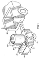
- Figures 1-4 show a first embodiment of the present invention.
- a trailer 10 holds a keg 14, a cooler 16 and a tap 18 from which beverage within the keg and cooler discharge.
- the keg 14 contains beer which flows through a hose 20 to the cooler where it is chilled. From the cooler, the beer flows through a second hose 22 to the tap 18 from which it discharges.
- hoses 20 and 22 are composed of braided polyvinyl chloride.
- the trailer 10 is mounted on wheels 24 so that it can be towed by a motorized golf cart 26.
- the keg 14 can be removed from the trailer when it is empty and replaced by another full keg.
- Beer within the keg 14 is maintained under pressure by means of so called “beer gas” stored in a conventional pneumatic or gas cylinder 30. Beer gas is usually composed of from about 65 to 75 percent nitrogen and the remainder carbon dioxide. The gas is introduced into the interior of the keg 14 through a hose 32 which extends from the cylinder to the keg. A nozzle and pressure gauge (not illustrated) both of conventional construction are provided in the gas line so that the pressure within the keg can be monitored and controlled. A compressor can also be used.
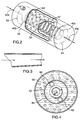
- a conduit or coil 40 extends through the cooler 16.
- the coil has a point of entry 40a at which beer enters the coil. From the point of entry, the beer enters an upstream segment 40b and from the upstream segment, the beer flows to a downstream segment 40c.
- the inner diameter of the coil decreases downstream of the flow of beer.
- the inner wall of the coil diminishes gradually but the decrease may be abrupt.
- the inner diameter of the upstream segment is greater than that of the downstream segment.
- the two segments may be interconnected by a joint of conventional construction.
- the two segments of the coil are composed of stainless steel and each has a constant inner diameter.
- the inner diameter of the coil at the point of entry 40a is about 9.5 mm (3/8 inch) as is that of hose 20 through which the beer flows to the cooler from the keg.
- the upstream segment 40b has an inner diameter of about 6.4 mm (1/4 inch) while the downstream segment has an inner diameter of 4.8 mm (3/6 inch).
- the upstream segment should be about 18.3 to about 21.3 m (60 to about 70 feet) in length measured along the longitudinal axis of the coil. Any shorter than 18.3 m (60 feet) and the volume of beer at the desired temperature will diminish while any longer than 21.3 m (70 feet), while permissible, will necessitate a higher pressure of beer gas to cause the beer to flow at a satisfactory rate.
- the preferred pressure of beer gas is about 3.1 to 3.8 bar (45 to 55 p.s.i.).
- the pressure of beer gas is most preferably 3.2 bar (47 p.s.i.).
- the downstream segment should be about 0.9 m (3 feet) in length measured along the longitudinal axis of the coil. Significantly longer and the flow of beer will diminish to a trickle and significantly shorter and foaming becomes a problem.
- the downstream segment terminates at the tap and accordingly it will straighten at 40d at its downstream end. While it is desirable that the downstream segment be substantially entirely within the cooler, the apparatus will still work if the downstream segment is partly within and partly outside the cooler.
- the coil is mounted within a perforated vessel or cylinder 50 which is closed at both ends 52, 54.
- the cylinder is mounted within cooler 16 which has solid sides and end walls.
- the cooler contains water and particles of ice 56 which serve to cool the beer within the coil.
- a drain (not illustrated) is provided at the bottom of the cooler through which the water can be drawn off.
- a faucet (not illustrated) is provided in the discharge line for controlling the flow from the drain.
- An opening is formed on the top of cooler for admission of fresh water and ice particles.
- the opening is closed by a lid (not illustrated) for preventing the contents of the vessel from spilling out when the trailer is moving.
- Two submersible pumps 60, 62 are mounted within the vessel to cause the water to circulate.
- the water circulates freely around the pumps but the ice particles are prevented from contacting and damaging the pump because they are too large to penetrate through the perforations 64 in cylinder 50.
- a pump suitable for causing the water and ice particles to circulate is submersible pump model V500 no. 4204 sold by Attwood Company.
- the pump is powered by a 12 volt battery.
- the battery is mounted on the trailer so that the trailer is completely portable and self-contained.
- cooled beer flows from the coil to tap 18.
- the tap is of conventional construction and is spring-loaded closed. Such a tap ensures that pressure within the line through which beer flows is maintained at the desired value at all times except when the tap is opened to dispense beer.
- the beer cooler described above is capable of cooling beer from ambient temperature to a temperature in the range of about 0 to 1.1 degrees C (32 to 34 degrees F). This is the range generally favoured by most consumers of beer brewed in North America. Thus the temperature of the beer in the keg will be ambient while the temperature at tap 18 will be about 0 to 1.1 degrees.
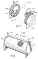
- FIG. 5 to 15 A second embodiment of the apparatus is shown in Figures 5 to 15. This embodiment is preferably for use with beer, although it can be for use with other carbonated and non-carbonated beverages.
- a housing 110 is preferably composed of fiberglass, but may be of any appropriate material known to those skilled in the art.
- the housing 110 is mounted on a frame 160 which is preferably composed of steel or aluminum to provide structural support for the housing.
- the frame 160 is preferably equipped with wheels and a hitch to enable it to be towed behind a golf cart, all terrain vehicle, truck or any other such vehicle with suitable towing capabilities.
- the preferred embodiment of the housing 110 preferably defines 4 chambers, 120, 140, 150 and 180 but in another embodiment the housing may define as few as one chamber.
- Chamber 120 is watertight.
- the housing 110 defines an opening 121 which permits a mixture of preferably water and ice to be poured into the chamber 120.
- a lid 122 seals chamber 120.
- Other appropriate cooling liquids or fluids are also acceptable.
- a coil 170 is mounted to the bottom of the chamber 120 and is surrounded by the liquid and ice mixture.
- Agitators 171 and 172 are located in chamber 120 for agitating the water and ice. Preferably the agitators are submersible pumps. In alternate embodiments it is possible to locate the keg outside of the housing in a manner similar to that described with the first embodiment.
- the housing 110 defines openings 130 which run from the chamber 120 to the outer wall of the housing 110.
- Hose 131 is preferably 4.8 mm (3/16th inch) in diameter and four to five feet in length.
- Hose 133 is preferably 9.5 mm (3/8th inch) in diameter and 1.2 to 3 m (five to ten feet) in length.
- the hoses 131 and 133 are preferably composed of braided polyvinyl chloride.
- the chamber 140 provides a hinged access door 143 which permits one or more beer kegs 141 to be placed inside.
- Hose 133 connects the coil 170 to the keg 141.
- Mounting brackets plus adjustable straps (not illustrated) are provided to secure keg 141 in place.
- a keg coupler 142 is threadably received into a port on the top of the keg 141.
- the keg coupler 142 provides a blow out valve with a preset pressure limit of 4.1 bar (60 p.s.i), significantly higher than the pressure limit of standard North American keg couplers.
- Hose 182 attaches to the keg coupler and is preferably composed of braided polyvinyl chloride.
- Chamber 180 provides a housing for the gas cylinder 181 or compressor in a secure manner.
- a hinged door is provided to enable easy access to remove and replace cylinder 181.
- Hose 182 is also attached to a pressurizing means 181 housed in chamber 180.
- the pressurizing means is preferably so called “beer gas” stored in a conventional pneumatic or gas cylinder 181. Beer gas is usually composed of from about 65 to 75 percent nitrogen and the remainder carbon dioxide. Any gas can be used which does not affect the flavour of the beverage stored in the keg 141, for example pure carbon dioxide or even compressed air.
- the gas is introduced into the interior of the keg 141 through hose 182 which extends from the cylinder 181 to the keg 141.
- a nozzle and pressure gauge both of conventional construction are provided in the gas line so that the pressure within the keg can be monitored and controlled.
- An alternate means to pressurize the interior of the keg 141 is through the use of a compressor instead of a pre-pressurized gas cylinder.
- Chamber 150 provides a housing for a portable power source 151 capable of operating the agitators 171 and 172.
- the power source 151 is preferably a 12 volt battery but may be any form of portable power, such as a generator.
- the power source 151 is connected to the agitators 171 and 172 by way of wiring 152.
- the wiring passes into chamber 120 and is waterproof. The opening through which the wire passes is sealed around the wire such that the liquid and ice mixture in chamber 120 does not seep out.
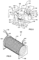
- Conduit 400 comprises hoses 131 and 133 and coil 170 and is shown in Figure 6.
- Other conduits that permit the flow of a fluid or liquid and which permit satisfactory heat exchange to cool the beverage flowing through the conduit are also acceptable.
- any form of metal or steel tubing that permits heat exchange is acceptable. Notable exceptions are copper and lead which can poison the beverage.
- Conduit 400 is preferably substantially 21.3 m (70 feet) long. Slight variations of the length of the conduit are possible.
- the conduit is 9.5 mm (3/8 inch) for the first 1.5 m (5 feet).
- the inner diameter of the conduit is decreased to 6.3 mm (1/4 inch) at the 1.5 m (5 foot) point along the length of the conduit.
- the inner diameter is preferably 6.3 mm (1/4 inch) from the 1.5 m (5 foot) point to the 19.8 m (65 foot) point along the length of the conduit and is described herein as coil 170.
- the inner diameter of the conduit is decreased to 4.8 mm (3/16 inch) at the 19.8 m (65 foot) point along the length of the conduit.
- the inner diameter is preferably 4.8 mm (3/16 inch) from the 19.8 m (65 foot) point to the 21.3 m (70 foot) point along the length of the conduit.
- the first 1.5 m (5 feet) and the last 1.5 m (5 feet) of the conduit are preferably composed of braided polyvinyl chloride and have been described herein as hoses 131 and 133.
- the total length of the conduit can be in the range of 18.3 to 21.3 m (60 to 70 feet). If the conduit is shorter than 18.3 m (60 feet) then the volume of beer at the desired temperature will diminish. If the conduit is longer than 21.3 m (70 feet), a higher pressure of beer gas is required to cause the beer to flow at a satisfactory rate.
- two or more conduits 170 can be wound into a coil thereby permitting more than one beer line to be cooled simultaneously.
- conduit 400 is composed of stainless steel, although any appropriate material or combinations of materials may be used the selection of which will be apparent to one skilled in the art.
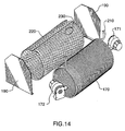
- Coil 170 is mounted inside a perforated vessel 300 with solid anterior and posterior side plates 190.
- Perforated vessel 300 is shown in Figures 8, 14 and 15 and is described in greater detail below.
- the inner circumference of coil 170 wound as a coil is of sufficient size to permit the placement of agitators 171 and 172 therein.
- Agitators 171 and 172 are shown in Figures 7 and 12-15 and are described in greater detail below.
- the preferred pressure of beer gas in the container 141 is about 3.1 to 3.8 bar (45 to 55 p.s.i.).
- Hose 133 is preferably 9.5 mm (3/8th inch) in diameter and decreases to 6.3 mm (1/4 inch) inner diameter at the point of connection 210 to the coil 170, however the decrease may also be abrupt.
- the two segments may be interconnected by a joint of conventional constructions.
- Hose 133 is preferably of a length in the range of 1.5 to 3 m (five to ten feet).
- the hose 133 is of a significantly lesser diameter than the container 141. As such any beer is forced into hose 133 is subject to greater pressures which begins to entrain gas which has separated from the beer.
- the hose 131 is connected to coil 170 at a connection 200.
- the two segments may be interconnected by a joint of conventional constructions.
- the downstream end of hose 131 connects to a dispensing means 132.
- Hose 131 is preferably 6.3 mm (1/4 inch) in diameter and tapers to 4.8 mm (3/16th inch) diameter at dispensing means 132, however the decrease may also be abrupt.
- Hose 131 is preferably of a length in the range of 1.2 to 1.5 m (four to five feet). Significantly longer and the flow of beer will diminish to a trickle and significantly shorter and foaming becomes a problem.
- the hose 131 is of a lesser diameter than the coil 170.
- any beer which is forced into hose 131 is subject to greater pressures than the beer was subject to in coil 170. As such any remaining separated gas is reintroduced into the beer. While it is desirable that hose 131 be substantially entirely within the chamber 120, the apparatus will still work if hose 131 is partly within and partly outside chamber 120.
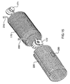
- the coil 170 is surrounded by a perforated vessel or cylinder 220 shown in Figures 8, 14 and 15 which is closed on the anterior and posterior sides with solid metal plates 190.
- the cylinder 220 and the sides are preferably made of a resilient non-corrosive substance such as stainless steel or plastic, however, any appropriate substance can be used and will be known to a person skilled in the art.
- the vessel 300 has openings sufficient to permit the connecting ends of the coil 210 and 200 to protrude there from.
- the vessel 300 is preferably mounted on the bottom and in the center of chamber 120, but may be mounted anywhere within said chamber.
- the perforations 230 are preferably 3.2 mm (1/8th inch) in diameter and evenly spaced 3.2 mm (1/8th inch) apart across the entire surface of the perforated vessel 220.
- the perforations filter ice particles from the liquid and ice mixture in order that the agitators 171 and 172 are not damaged from drawing large ice particles into the their intake ports 175.
- the preferred sizing and spacing of the perforations permits a sufficient volume of liquid to be drawn through the perforated vessel 220 by way of the agitators.
- any configuration of perforation size and spacing may be used so long as the agitators are not being damaged and can draw sufficient liquid to provide adequate cooling of the beer in the coil 170. If the agitators have adequate filters on their intake ports 175, the perforated vessel 220 may not be necessary at all.
- the agitators are submersible pumps.
- the pumps are capable of processing 1.9 m 3 (500 gallons) of water per hour.
- submersible pumps that process more or less water per minute, or even only one submersible pump may be used provided they or it are capable of sufficiently agitating the liquid and ice mixture to cool the beer in the coil 170 and there is a sufficient power supply to operate them or it.
- the agitators may not need to be submersible pumps (not illustrated) and may be pumps located externally to chamber 120. Such externally located pumps would be connected to chamber 120 by way of hoses which port into chamber 120. Such externally located pumps could agitate the water and ice mixture by way of drawing in said mixture through an intake port hose and expelling it through an outtake port hose.
- agitators 171 and 172 are mounted on the anterior and posterior side plates 190 of the perforated vessel 300. The mounting of the pumps in such a manner places them inside the inner circumference of coil 170.
- agitators 171 and 172 are oriented in such a manner that their respective discharge nozzles 173 and 174 are horizontally and laterally diagonally spaced along the longitudinal axis of the coil 170 and directed toward the centre thereof.
- Agitator 171 is located on the same side of the coil 170 as the connection point 210.
- Agitator 172 is located on the same side of the coil 170 as the connection point 200.
- the preferred position of the agitators imparts a vorticular flow to the liquid and ice mixture which provides for maximum cooling of the beer in the coil 170, while also minimizing the draw on the portable power supply 151 to operate the agitators.
- the agitators may be only laterally or horizontally spaced along the longitudinal axis of the coil 170 with their respective discharge nozzles 173 and 174 pointing toward the centre thereof.
- the discharge nozzles 173 and 174 may be directed in any direction suitable for sufficiently agitating the liquid and ice mixture to adequately cool the beer.
- the intake ports 175 on the agitators are positioned to abut the walls of the coil 170.
- the intake ports 175 draw liquid through the perforated vessel 300 and over the exterior of coil 170.
- the perforated vessel 300 prevents large ice particles from the liquid and ice mixture from being drawn into the agitators 171 and 172.
- An agitator suitable for causing the liquid and ice mixture to agitate is submersible pump model V500 no. 4204 sold by Attwood Company.
- the agitators 171 and 172 are powered by a 12 volt battery and draws 1.5 amperes current.
- the portable power supply 151 may be a battery of sufficient voltage or any other appropriate power source known to those skilled in the art.
- the portable power supply 151 is located in chamber 150. Wiring 151 is connected to the power supply 151, is routed through chamber 120 and is connected to agitators 171 and 172. Wiring 151 is shielded against contact with the liquid and ice mixture.
- the keg 141 contains beer at an ambient temperature.
- the keg 141 is pressurized by way of a gas cylinder 181 or compressor which forces compressed gas through hose 182, into the keg coupler 142 which is threadably received into keg 141.
- the pressure must be sufficient to force the beverage into and through the entire length of coil 170 and hoses 133 and 131. It is preferable to use pressure in the range of 3.1 to 3.8 bar (45 to 55 p.s.i), in particular 3.2 bar (47 p.s.i.) is ideal.
- the beer flows from keg 141, through the keg coupler 142 to a hose 133.
- the beer flows from the hose 133 to the coil 170.
- the beer flows through a second hose 131 to the tap 132 from which the beer may be selectively discharged. Any gases which have escaped from the beer while it is stored in the keg 141 are entrained into the beer by way of forcing the beer under pressure through hose 133, coil 170 and hose 131.
- the diameter of hose or conduit through which the beer is forced is reduced.
- the coil 170 is cooled by the liquid and ice mixture as it is agitated around the coil. Rapid and thorough heat exchange along the entire length of the coil 170 is achieved by the continuous and uninterrupted flow of the chilled liquid portion of said mixture over the coil.
- the positioning of the agitators is such the agitators discharges the chilled liquid of said mixture onto the side plates 190.
- the liquid impacts the side plates 190 with sufficient power to be deflected over the exterior of coil 170 and out through the perforations 230.
- the liquid exits the perforations and with sufficient power to impart a vorticular flow pattern with its nexus located at the centre of the longitudinal axis of the coil 170.
- the vorticular flow pattern circulates the chilled liquid of said mixture such that there is maximum uniform surface exposure to the coil 170 thereby ensuring that the entire coil is evenly cooled. As well, the vorticular flow pattern ensures the entire liquid of said mixture is utilized to cool the coil 170, not just that portion of chilled liquid in direct proximity with the coil.
- the beer is preferably cooled to a temperature in the range of 0 to 1.1 degrees C (32 to 34 degrees Fahrenheit). As it passes through the coil the cooling of the beer further reduces any foaming and permits more of the separated gases to be reintroduced into the beer.
- Non-foamed beverage is continuously delivered from the conduit to the exterior of the housing by way of a dispensing tap.
- the taps are spring loaded to prevent them from jarring open over rough terrain.
- cooler of the subject invention may be used to cool any carbonated beverage and may be stationary as well as mobile.
- the drawings and description are intended to be illustrative of one way in which the subject invention may be put into practice. They are not intended however to limit the scope of the invention, which is defined by the apended claims.
Landscapes
- Engineering & Computer Science (AREA)
- Physics & Mathematics (AREA)
- Thermal Sciences (AREA)
- Mechanical Engineering (AREA)
- General Engineering & Computer Science (AREA)
- Chemical & Material Sciences (AREA)
- Combustion & Propulsion (AREA)
- Devices For Dispensing Beverages (AREA)
- Devices That Are Associated With Refrigeration Equipment (AREA)
- Tea And Coffee (AREA)
Priority Applications (1)
| Application Number | Priority Date | Filing Date | Title |
|---|---|---|---|
| EP05077394A EP1626030A3 (en) | 2001-06-22 | 2002-06-19 | Beverage cooler |
Applications Claiming Priority (3)
| Application Number | Priority Date | Filing Date | Title |
|---|---|---|---|
| US887973 | 2001-06-22 | ||
| US09/887,973 US6502415B2 (en) | 2000-01-20 | 2001-06-22 | Beverage cooler |
| PCT/CA2002/000924 WO2003008326A2 (en) | 2001-06-22 | 2002-06-19 | Beverage cooler |
Related Child Applications (1)
| Application Number | Title | Priority Date | Filing Date |
|---|---|---|---|
| EP05077394A Division EP1626030A3 (en) | 2001-06-22 | 2002-06-19 | Beverage cooler |
Publications (2)
| Publication Number | Publication Date |
|---|---|
| EP1401760A2 EP1401760A2 (en) | 2004-03-31 |
| EP1401760B1 true EP1401760B1 (en) | 2006-01-18 |
Family
ID=25392258
Family Applications (2)
| Application Number | Title | Priority Date | Filing Date |
|---|---|---|---|
| EP02744970A Expired - Lifetime EP1401760B1 (en) | 2001-06-22 | 2002-06-19 | Beverage cooler |
| EP05077394A Withdrawn EP1626030A3 (en) | 2001-06-22 | 2002-06-19 | Beverage cooler |
Family Applications After (1)
| Application Number | Title | Priority Date | Filing Date |
|---|---|---|---|
| EP05077394A Withdrawn EP1626030A3 (en) | 2001-06-22 | 2002-06-19 | Beverage cooler |
Country Status (13)
| Country | Link |
|---|---|
| US (1) | US6502415B2 (enExample) |
| EP (2) | EP1401760B1 (enExample) |
| JP (1) | JP2004534705A (enExample) |
| AT (1) | ATE316063T1 (enExample) |
| AU (1) | AU2002317069B2 (enExample) |
| BR (1) | BR0211044A (enExample) |
| CA (1) | CA2471580A1 (enExample) |
| CO (1) | CO5540334A2 (enExample) |
| DE (1) | DE60208793D1 (enExample) |
| IL (1) | IL159484A0 (enExample) |
| MX (1) | MXPA03011960A (enExample) |
| NZ (1) | NZ530686A (enExample) |
| WO (1) | WO2003008326A2 (enExample) |
Families Citing this family (13)
| Publication number | Priority date | Publication date | Assignee | Title |
|---|---|---|---|---|
| CA2391674A1 (en) * | 2002-06-26 | 2003-12-26 | Sam Chiusolo | Miniature beverage cooler |
| CA2489487A1 (en) * | 2004-12-09 | 2006-06-09 | Icefloe Technologies Inc. | Portable apparatus for chilling draught beverages |
| US20060144439A1 (en) * | 2004-12-30 | 2006-07-06 | Bell Samuel R | Siphon generator |
| US7444831B2 (en) * | 2005-10-27 | 2008-11-04 | Iceberg Dispensing Systems, Ltd. | Method and apparatus for cooling beverages |
| US7861892B1 (en) | 2008-03-04 | 2011-01-04 | White Richard W | Portable draft bar |
| WO2010034330A1 (en) * | 2008-09-26 | 2010-04-01 | Electrolux Home Products Corporation N.V. | A beverage cooler, a refrigerator comprising such a beverage cooler and a method for cooling beverage |
| US20100237100A1 (en) * | 2009-03-21 | 2010-09-23 | Broussard Kenneth W | Beverage storage and dispensing system |
| USD693183S1 (en) | 2009-11-30 | 2013-11-12 | Yong C. Lyles | Combined portable chiller and dispensing unit |
| US20120132673A1 (en) | 2010-02-12 | 2012-05-31 | Robert Leyva | Foam Resistant Keg Dispenser |
| ITBO20110430A1 (it) * | 2011-07-18 | 2013-01-19 | Vinicio Colombari | Macchina per la refrigerazione di liquidi ad uso alimentare, in particolare acqua. |
| CN103889564B (zh) | 2011-10-11 | 2016-04-06 | 流量控制有限责任公司 | 用于饮料应用的内嵌式按需可调节的碳酸饱和室 |
| WO2015061564A1 (en) | 2013-10-24 | 2015-04-30 | Robert Leyva | Versatile and aesthetically refined keg dispenser |
| MY186369A (en) * | 2016-10-06 | 2021-07-17 | Singh Bal Sarandev | Multi-purpose instant chiller-heater apparatus |
Family Cites Families (14)
| Publication number | Priority date | Publication date | Assignee | Title |
|---|---|---|---|---|
| US34648A (en) | 1862-03-11 | Improved condenser for stills | ||
| US1622376A (en) | 1925-09-08 | 1927-03-29 | Chicago Pneumatic Tool Co | Apparatus for refrigerating systems |
| DE646207C (de) * | 1934-12-14 | 1937-06-12 | Robert Bosch Akt Ges | Getraenkekuehler |
| US2271648A (en) | 1937-05-28 | 1942-02-03 | Dole Refrigerating Co | Liquid cooling device |
| US2223152A (en) | 1940-01-08 | 1940-11-26 | Nagin Max | Beer cooling device |
| US2917906A (en) | 1956-09-24 | 1959-12-22 | Woolley George Craig | Portable cooler, gasser, and dispenser for keg beer and the like |
| US3605430A (en) * | 1969-05-22 | 1971-09-20 | Follett Corp | System for cooling beverages |
| US3865276A (en) * | 1973-11-26 | 1975-02-11 | Hank A Thompson | Portable keg tapper |
| US4225059A (en) | 1978-12-14 | 1980-09-30 | Christopher Kappos | Portable beverage cooler and dispenser |
| US5079927A (en) | 1985-11-26 | 1992-01-14 | Rodino A J | Beer cooling apparatus |
| US5035121A (en) * | 1990-07-25 | 1991-07-30 | Imi Cornelius Inc. | Beverage cooling and pumping system |
| US5280711A (en) * | 1993-02-25 | 1994-01-25 | Imi Cornelius Inc. | Low cost beverage dispensing apparatus |
| JP3524610B2 (ja) * | 1995-01-23 | 2004-05-10 | ホシザキ電機株式会社 | 飲料冷却注出装置 |
| FR2791051B1 (fr) * | 1999-03-19 | 2001-04-13 | Michel Delcourt | Distributeur autonome mobile ou fixe de boisson refrigeree |
-
2001
- 2001-06-22 US US09/887,973 patent/US6502415B2/en not_active Expired - Fee Related
-
2002
- 2002-06-19 IL IL15948402A patent/IL159484A0/xx unknown
- 2002-06-19 AT AT02744970T patent/ATE316063T1/de not_active IP Right Cessation
- 2002-06-19 DE DE60208793T patent/DE60208793D1/de not_active Expired - Lifetime
- 2002-06-19 EP EP02744970A patent/EP1401760B1/en not_active Expired - Lifetime
- 2002-06-19 NZ NZ530686A patent/NZ530686A/en unknown
- 2002-06-19 BR BR0211044-0A patent/BR0211044A/pt active Search and Examination
- 2002-06-19 CA CA002471580A patent/CA2471580A1/en not_active Abandoned
- 2002-06-19 EP EP05077394A patent/EP1626030A3/en not_active Withdrawn
- 2002-06-19 JP JP2003513891A patent/JP2004534705A/ja active Pending
- 2002-06-19 AU AU2002317069A patent/AU2002317069B2/en not_active Ceased
- 2002-06-19 MX MXPA03011960A patent/MXPA03011960A/es active IP Right Grant
- 2002-06-19 WO PCT/CA2002/000924 patent/WO2003008326A2/en not_active Ceased
-
2003
- 2003-12-22 CO CO03111719A patent/CO5540334A2/es not_active Application Discontinuation
Also Published As
| Publication number | Publication date |
|---|---|
| WO2003008326A2 (en) | 2003-01-30 |
| CO5540334A2 (es) | 2005-07-29 |
| EP1626030A2 (en) | 2006-02-15 |
| CA2471580A1 (en) | 2003-01-30 |
| US20020011076A1 (en) | 2002-01-31 |
| NZ530686A (en) | 2006-10-27 |
| EP1401760A2 (en) | 2004-03-31 |
| ATE316063T1 (de) | 2006-02-15 |
| US6502415B2 (en) | 2003-01-07 |
| WO2003008326A3 (en) | 2003-05-30 |
| IL159484A0 (en) | 2004-06-01 |
| EP1626030A3 (en) | 2006-05-17 |
| BR0211044A (pt) | 2004-10-26 |
| MXPA03011960A (es) | 2005-03-07 |
| AU2002317069B2 (en) | 2007-11-29 |
| JP2004534705A (ja) | 2004-11-18 |
| WO2003008326A9 (en) | 2004-02-26 |
| DE60208793D1 (de) | 2006-04-06 |
Similar Documents
| Publication | Publication Date | Title |
|---|---|---|
| EP1401760B1 (en) | Beverage cooler | |
| US4928853A (en) | End aisle fluid mixing and dispensing system | |
| JP3490440B2 (ja) | 清涼飲料を調製して送出するための装置 | |
| US7757908B1 (en) | Portable container and dispenser for kegged beer | |
| US6622510B2 (en) | Frozen beer product, method and apparatus | |
| AU2002317069A1 (en) | Beverage cooler | |
| US6637224B2 (en) | Beverage cooler | |
| JP2000142892A (ja) | 流体分配装置の冷却ヘッド用システム | |
| US9027792B2 (en) | Beer dispensing device and system | |
| US20070051125A1 (en) | Portable apparatus for chilling draught beverages | |
| US6981441B1 (en) | Fresh brewed ice beverage dispensing system | |
| NZ549360A (en) | Beverage cooler | |
| US20160347597A1 (en) | Beverage transport and dispensing cart | |
| JP5670658B2 (ja) | 飲料ディスペンサ | |
| WO2004002876A1 (en) | Miniature beverage cooler | |
| WO2002100767A1 (en) | Beverage cooler | |
| CA2331943A1 (en) | Beverage cooler | |
| JP2889609B2 (ja) | 炭酸水製造供給装置 | |
| GB1560753A (en) | Carbonators | |
| AU2005301036A1 (en) | Inline booster with spraying means for beverage dispensing system | |
| CA2530176A1 (en) | Portable apparatus for chilling draught beverages | |
| JPH0589357A (ja) | カツプ式自動販売機の冷却装置 | |
| JPH0620153A (ja) | 飲料ディスペンサ |
Legal Events
| Date | Code | Title | Description |
|---|---|---|---|
| PUAI | Public reference made under article 153(3) epc to a published international application that has entered the european phase |
Free format text: ORIGINAL CODE: 0009012 |
|
| 17P | Request for examination filed |
Effective date: 20040122 |
|
| AK | Designated contracting states |
Kind code of ref document: A2 Designated state(s): AT BE CH CY DE DK ES FI FR GB GR IE IT LI LU MC NL PT SE TR |
|
| AX | Request for extension of the european patent |
Extension state: AL LT LV MK RO SI |
|
| 17Q | First examination report despatched |
Effective date: 20040730 |
|
| GRAP | Despatch of communication of intention to grant a patent |
Free format text: ORIGINAL CODE: EPIDOSNIGR1 |
|
| GRAS | Grant fee paid |
Free format text: ORIGINAL CODE: EPIDOSNIGR3 |
|
| GRAA | (expected) grant |
Free format text: ORIGINAL CODE: 0009210 |
|
| AK | Designated contracting states |
Kind code of ref document: B1 Designated state(s): AT BE CH CY DE DK ES FI FR GB GR IE IT LI LU MC NL PT SE TR |
|
| PG25 | Lapsed in a contracting state [announced via postgrant information from national office to epo] |
Ref country code: IT Free format text: LAPSE BECAUSE OF FAILURE TO SUBMIT A TRANSLATION OF THE DESCRIPTION OR TO PAY THE FEE WITHIN THE PRESCRIBED TIME-LIMIT;WARNING: LAPSES OF ITALIAN PATENTS WITH EFFECTIVE DATE BEFORE 2007 MAY HAVE OCCURRED AT ANY TIME BEFORE 2007. THE CORRECT EFFECTIVE DATE MAY BE DIFFERENT FROM THE ONE RECORDED. Effective date: 20060118 Ref country code: LI Free format text: LAPSE BECAUSE OF FAILURE TO SUBMIT A TRANSLATION OF THE DESCRIPTION OR TO PAY THE FEE WITHIN THE PRESCRIBED TIME-LIMIT Effective date: 20060118 Ref country code: FI Free format text: LAPSE BECAUSE OF FAILURE TO SUBMIT A TRANSLATION OF THE DESCRIPTION OR TO PAY THE FEE WITHIN THE PRESCRIBED TIME-LIMIT Effective date: 20060118 Ref country code: AT Free format text: LAPSE BECAUSE OF FAILURE TO SUBMIT A TRANSLATION OF THE DESCRIPTION OR TO PAY THE FEE WITHIN THE PRESCRIBED TIME-LIMIT Effective date: 20060118 Ref country code: NL Free format text: LAPSE BECAUSE OF FAILURE TO SUBMIT A TRANSLATION OF THE DESCRIPTION OR TO PAY THE FEE WITHIN THE PRESCRIBED TIME-LIMIT Effective date: 20060118 Ref country code: CH Free format text: LAPSE BECAUSE OF FAILURE TO SUBMIT A TRANSLATION OF THE DESCRIPTION OR TO PAY THE FEE WITHIN THE PRESCRIBED TIME-LIMIT Effective date: 20060118 Ref country code: BE Free format text: LAPSE BECAUSE OF FAILURE TO SUBMIT A TRANSLATION OF THE DESCRIPTION OR TO PAY THE FEE WITHIN THE PRESCRIBED TIME-LIMIT Effective date: 20060118 |
|
| REG | Reference to a national code |
Ref country code: GB Ref legal event code: FG4D |
|
| REG | Reference to a national code |
Ref country code: CH Ref legal event code: EP |
|
| REG | Reference to a national code |
Ref country code: IE Ref legal event code: FG4D |
|
| REF | Corresponds to: |
Ref document number: 60208793 Country of ref document: DE Date of ref document: 20060406 Kind code of ref document: P |
|
| PG25 | Lapsed in a contracting state [announced via postgrant information from national office to epo] |
Ref country code: DK Free format text: LAPSE BECAUSE OF FAILURE TO SUBMIT A TRANSLATION OF THE DESCRIPTION OR TO PAY THE FEE WITHIN THE PRESCRIBED TIME-LIMIT Effective date: 20060418 Ref country code: SE Free format text: LAPSE BECAUSE OF FAILURE TO SUBMIT A TRANSLATION OF THE DESCRIPTION OR TO PAY THE FEE WITHIN THE PRESCRIBED TIME-LIMIT Effective date: 20060418 |
|
| PG25 | Lapsed in a contracting state [announced via postgrant information from national office to epo] |
Ref country code: DE Free format text: LAPSE BECAUSE OF FAILURE TO SUBMIT A TRANSLATION OF THE DESCRIPTION OR TO PAY THE FEE WITHIN THE PRESCRIBED TIME-LIMIT Effective date: 20060419 |
|
| PG25 | Lapsed in a contracting state [announced via postgrant information from national office to epo] |
Ref country code: ES Free format text: LAPSE BECAUSE OF FAILURE TO SUBMIT A TRANSLATION OF THE DESCRIPTION OR TO PAY THE FEE WITHIN THE PRESCRIBED TIME-LIMIT Effective date: 20060429 |
|
| PG25 | Lapsed in a contracting state [announced via postgrant information from national office to epo] |
Ref country code: PT Free format text: LAPSE BECAUSE OF FAILURE TO SUBMIT A TRANSLATION OF THE DESCRIPTION OR TO PAY THE FEE WITHIN THE PRESCRIBED TIME-LIMIT Effective date: 20060619 |
|
| PG25 | Lapsed in a contracting state [announced via postgrant information from national office to epo] |
Ref country code: MC Free format text: LAPSE BECAUSE OF NON-PAYMENT OF DUE FEES Effective date: 20060630 |
|
| NLV1 | Nl: lapsed or annulled due to failure to fulfill the requirements of art. 29p and 29m of the patents act | ||
| REG | Reference to a national code |
Ref country code: CH Ref legal event code: PL |
|
| PLBE | No opposition filed within time limit |
Free format text: ORIGINAL CODE: 0009261 |
|
| STAA | Information on the status of an ep patent application or granted ep patent |
Free format text: STATUS: NO OPPOSITION FILED WITHIN TIME LIMIT |
|
| 26N | No opposition filed |
Effective date: 20061019 |
|
| EN | Fr: translation not filed | ||
| PGFP | Annual fee paid to national office [announced via postgrant information from national office to epo] |
Ref country code: IE Payment date: 20070629 Year of fee payment: 6 |
|
| PGFP | Annual fee paid to national office [announced via postgrant information from national office to epo] |
Ref country code: GB Payment date: 20070620 Year of fee payment: 6 |
|
| PG25 | Lapsed in a contracting state [announced via postgrant information from national office to epo] |
Ref country code: FR Free format text: LAPSE BECAUSE OF FAILURE TO SUBMIT A TRANSLATION OF THE DESCRIPTION OR TO PAY THE FEE WITHIN THE PRESCRIBED TIME-LIMIT Effective date: 20070309 Ref country code: GR Free format text: LAPSE BECAUSE OF FAILURE TO SUBMIT A TRANSLATION OF THE DESCRIPTION OR TO PAY THE FEE WITHIN THE PRESCRIBED TIME-LIMIT Effective date: 20060419 |
|
| PG25 | Lapsed in a contracting state [announced via postgrant information from national office to epo] |
Ref country code: TR Free format text: LAPSE BECAUSE OF FAILURE TO SUBMIT A TRANSLATION OF THE DESCRIPTION OR TO PAY THE FEE WITHIN THE PRESCRIBED TIME-LIMIT Effective date: 20060118 Ref country code: LU Free format text: LAPSE BECAUSE OF NON-PAYMENT OF DUE FEES Effective date: 20060619 |
|
| PG25 | Lapsed in a contracting state [announced via postgrant information from national office to epo] |
Ref country code: CY Free format text: LAPSE BECAUSE OF FAILURE TO SUBMIT A TRANSLATION OF THE DESCRIPTION OR TO PAY THE FEE WITHIN THE PRESCRIBED TIME-LIMIT Effective date: 20060118 Ref country code: FR Free format text: LAPSE BECAUSE OF FAILURE TO SUBMIT A TRANSLATION OF THE DESCRIPTION OR TO PAY THE FEE WITHIN THE PRESCRIBED TIME-LIMIT Effective date: 20060118 |
|
| GBPC | Gb: european patent ceased through non-payment of renewal fee |
Effective date: 20080619 |
|
| PG25 | Lapsed in a contracting state [announced via postgrant information from national office to epo] |
Ref country code: IE Free format text: LAPSE BECAUSE OF NON-PAYMENT OF DUE FEES Effective date: 20080619 |
|
| PG25 | Lapsed in a contracting state [announced via postgrant information from national office to epo] |
Ref country code: GB Free format text: LAPSE BECAUSE OF NON-PAYMENT OF DUE FEES Effective date: 20080619 |