EP1401354B1 - Zeitweiliger intraluminaler filterführungsdraht - Google Patents
Zeitweiliger intraluminaler filterführungsdraht Download PDFInfo
- Publication number
- EP1401354B1 EP1401354B1 EP02753417A EP02753417A EP1401354B1 EP 1401354 B1 EP1401354 B1 EP 1401354B1 EP 02753417 A EP02753417 A EP 02753417A EP 02753417 A EP02753417 A EP 02753417A EP 1401354 B1 EP1401354 B1 EP 1401354B1
- Authority
- EP
- European Patent Office
- Prior art keywords
- filter
- proximal
- distal
- guidewire
- actuator
- Prior art date
- Legal status (The legal status is an assumption and is not a legal conclusion. Google has not performed a legal analysis and makes no representation as to the accuracy of the status listed.)
- Expired - Lifetime
Links
Images


Classifications
-
- A—HUMAN NECESSITIES
- A61—MEDICAL OR VETERINARY SCIENCE; HYGIENE
- A61B—DIAGNOSIS; SURGERY; IDENTIFICATION
- A61B17/00—Surgical instruments, devices or methods, e.g. tourniquets
- A61B17/12—Surgical instruments, devices or methods, e.g. tourniquets for ligaturing or otherwise compressing tubular parts of the body, e.g. blood vessels, umbilical cord
- A61B17/12022—Occluding by internal devices, e.g. balloons or releasable wires
- A61B17/12027—Type of occlusion
- A61B17/1204—Type of occlusion temporary occlusion
-
- A—HUMAN NECESSITIES
- A61—MEDICAL OR VETERINARY SCIENCE; HYGIENE
- A61B—DIAGNOSIS; SURGERY; IDENTIFICATION
- A61B17/00—Surgical instruments, devices or methods, e.g. tourniquets
- A61B17/12—Surgical instruments, devices or methods, e.g. tourniquets for ligaturing or otherwise compressing tubular parts of the body, e.g. blood vessels, umbilical cord
- A61B17/12022—Occluding by internal devices, e.g. balloons or releasable wires
- A61B17/12099—Occluding by internal devices, e.g. balloons or releasable wires characterised by the location of the occluder
- A61B17/12109—Occluding by internal devices, e.g. balloons or releasable wires characterised by the location of the occluder in a blood vessel
-
- A—HUMAN NECESSITIES
- A61—MEDICAL OR VETERINARY SCIENCE; HYGIENE
- A61B—DIAGNOSIS; SURGERY; IDENTIFICATION
- A61B17/00—Surgical instruments, devices or methods, e.g. tourniquets
- A61B17/12—Surgical instruments, devices or methods, e.g. tourniquets for ligaturing or otherwise compressing tubular parts of the body, e.g. blood vessels, umbilical cord
- A61B17/12022—Occluding by internal devices, e.g. balloons or releasable wires
- A61B17/12131—Occluding by internal devices, e.g. balloons or releasable wires characterised by the type of occluding device
- A61B17/12168—Occluding by internal devices, e.g. balloons or releasable wires characterised by the type of occluding device having a mesh structure
- A61B17/12172—Occluding by internal devices, e.g. balloons or releasable wires characterised by the type of occluding device having a mesh structure having a pre-set deployed three-dimensional shape
-
- A—HUMAN NECESSITIES
- A61—MEDICAL OR VETERINARY SCIENCE; HYGIENE
- A61F—FILTERS IMPLANTABLE INTO BLOOD VESSELS; PROSTHESES; DEVICES PROVIDING PATENCY TO, OR PREVENTING COLLAPSING OF, TUBULAR STRUCTURES OF THE BODY, e.g. STENTS; ORTHOPAEDIC, NURSING OR CONTRACEPTIVE DEVICES; FOMENTATION; TREATMENT OR PROTECTION OF EYES OR EARS; BANDAGES, DRESSINGS OR ABSORBENT PADS; FIRST-AID KITS
- A61F2/00—Filters implantable into blood vessels; Prostheses, i.e. artificial substitutes or replacements for parts of the body; Appliances for connecting them with the body; Devices providing patency to, or preventing collapsing of, tubular structures of the body, e.g. stents
- A61F2/01—Filters implantable into blood vessels
- A61F2/011—Instruments for their placement or removal
-
- A—HUMAN NECESSITIES
- A61—MEDICAL OR VETERINARY SCIENCE; HYGIENE
- A61F—FILTERS IMPLANTABLE INTO BLOOD VESSELS; PROSTHESES; DEVICES PROVIDING PATENCY TO, OR PREVENTING COLLAPSING OF, TUBULAR STRUCTURES OF THE BODY, e.g. STENTS; ORTHOPAEDIC, NURSING OR CONTRACEPTIVE DEVICES; FOMENTATION; TREATMENT OR PROTECTION OF EYES OR EARS; BANDAGES, DRESSINGS OR ABSORBENT PADS; FIRST-AID KITS
- A61F2/00—Filters implantable into blood vessels; Prostheses, i.e. artificial substitutes or replacements for parts of the body; Appliances for connecting them with the body; Devices providing patency to, or preventing collapsing of, tubular structures of the body, e.g. stents
- A61F2/01—Filters implantable into blood vessels
- A61F2/013—Distal protection devices, i.e. devices placed distally in combination with another endovascular procedure, e.g. angioplasty or stenting
-
- A—HUMAN NECESSITIES
- A61—MEDICAL OR VETERINARY SCIENCE; HYGIENE
- A61B—DIAGNOSIS; SURGERY; IDENTIFICATION
- A61B17/00—Surgical instruments, devices or methods, e.g. tourniquets
- A61B17/12—Surgical instruments, devices or methods, e.g. tourniquets for ligaturing or otherwise compressing tubular parts of the body, e.g. blood vessels, umbilical cord
- A61B17/12022—Occluding by internal devices, e.g. balloons or releasable wires
- A61B2017/1205—Introduction devices
- A61B2017/12054—Details concerning the detachment of the occluding device from the introduction device
- A61B2017/12095—Threaded connection
-
- A—HUMAN NECESSITIES
- A61—MEDICAL OR VETERINARY SCIENCE; HYGIENE
- A61B—DIAGNOSIS; SURGERY; IDENTIFICATION
- A61B17/00—Surgical instruments, devices or methods, e.g. tourniquets
- A61B17/22—Implements for squeezing-off ulcers or the like on the inside of inner organs of the body; Implements for scraping-out cavities of body organs, e.g. bones; Calculus removers; Calculus smashing apparatus; Apparatus for removing obstructions in blood vessels, not otherwise provided for
- A61B2017/22038—Implements for squeezing-off ulcers or the like on the inside of inner organs of the body; Implements for scraping-out cavities of body organs, e.g. bones; Calculus removers; Calculus smashing apparatus; Apparatus for removing obstructions in blood vessels, not otherwise provided for with a guide wire
- A61B2017/22045—Implements for squeezing-off ulcers or the like on the inside of inner organs of the body; Implements for scraping-out cavities of body organs, e.g. bones; Calculus removers; Calculus smashing apparatus; Apparatus for removing obstructions in blood vessels, not otherwise provided for with a guide wire fixed to the catheter; guiding tip
-
- A—HUMAN NECESSITIES
- A61—MEDICAL OR VETERINARY SCIENCE; HYGIENE
- A61F—FILTERS IMPLANTABLE INTO BLOOD VESSELS; PROSTHESES; DEVICES PROVIDING PATENCY TO, OR PREVENTING COLLAPSING OF, TUBULAR STRUCTURES OF THE BODY, e.g. STENTS; ORTHOPAEDIC, NURSING OR CONTRACEPTIVE DEVICES; FOMENTATION; TREATMENT OR PROTECTION OF EYES OR EARS; BANDAGES, DRESSINGS OR ABSORBENT PADS; FIRST-AID KITS
- A61F2/00—Filters implantable into blood vessels; Prostheses, i.e. artificial substitutes or replacements for parts of the body; Appliances for connecting them with the body; Devices providing patency to, or preventing collapsing of, tubular structures of the body, e.g. stents
- A61F2/01—Filters implantable into blood vessels
- A61F2002/018—Filters implantable into blood vessels made from tubes or sheets of material, e.g. by etching or laser-cutting
-
- A—HUMAN NECESSITIES
- A61—MEDICAL OR VETERINARY SCIENCE; HYGIENE
- A61F—FILTERS IMPLANTABLE INTO BLOOD VESSELS; PROSTHESES; DEVICES PROVIDING PATENCY TO, OR PREVENTING COLLAPSING OF, TUBULAR STRUCTURES OF THE BODY, e.g. STENTS; ORTHOPAEDIC, NURSING OR CONTRACEPTIVE DEVICES; FOMENTATION; TREATMENT OR PROTECTION OF EYES OR EARS; BANDAGES, DRESSINGS OR ABSORBENT PADS; FIRST-AID KITS
- A61F2230/00—Geometry of prostheses classified in groups A61F2/00 - A61F2/26 or A61F2/82 or A61F9/00 or A61F11/00 or subgroups thereof
- A61F2230/0002—Two-dimensional shapes, e.g. cross-sections
- A61F2230/0004—Rounded shapes, e.g. with rounded corners
- A61F2230/0006—Rounded shapes, e.g. with rounded corners circular
-
- A—HUMAN NECESSITIES
- A61—MEDICAL OR VETERINARY SCIENCE; HYGIENE
- A61F—FILTERS IMPLANTABLE INTO BLOOD VESSELS; PROSTHESES; DEVICES PROVIDING PATENCY TO, OR PREVENTING COLLAPSING OF, TUBULAR STRUCTURES OF THE BODY, e.g. STENTS; ORTHOPAEDIC, NURSING OR CONTRACEPTIVE DEVICES; FOMENTATION; TREATMENT OR PROTECTION OF EYES OR EARS; BANDAGES, DRESSINGS OR ABSORBENT PADS; FIRST-AID KITS
- A61F2230/00—Geometry of prostheses classified in groups A61F2/00 - A61F2/26 or A61F2/82 or A61F9/00 or A61F11/00 or subgroups thereof
- A61F2230/0063—Three-dimensional shapes
- A61F2230/0067—Three-dimensional shapes conical
-
- A—HUMAN NECESSITIES
- A61—MEDICAL OR VETERINARY SCIENCE; HYGIENE
- A61F—FILTERS IMPLANTABLE INTO BLOOD VESSELS; PROSTHESES; DEVICES PROVIDING PATENCY TO, OR PREVENTING COLLAPSING OF, TUBULAR STRUCTURES OF THE BODY, e.g. STENTS; ORTHOPAEDIC, NURSING OR CONTRACEPTIVE DEVICES; FOMENTATION; TREATMENT OR PROTECTION OF EYES OR EARS; BANDAGES, DRESSINGS OR ABSORBENT PADS; FIRST-AID KITS
- A61F2230/00—Geometry of prostheses classified in groups A61F2/00 - A61F2/26 or A61F2/82 or A61F9/00 or A61F11/00 or subgroups thereof
- A61F2230/0063—Three-dimensional shapes
- A61F2230/0071—Three-dimensional shapes spherical
Definitions
- the present invention relates generally to intraluminal devices for capturing particulate in the vessels of a patient. More particularly, the invention relates to a filter for capturing emboli in a blood vessel during an interventional vascular procedure and then removing the captured emboli from the patient after completion of the procedure. Furthermore, the invention concerns a filter mounted on a guidewire that can also be used to direct an interventional catheter to a treatment site within a patient.
- angioplasty balloon catheter is common in the art as a minimally invasive treatment to enlarge a stenotic or diseased blood vessel.
- this treatment is known as percutaneous transluminal coronary angioplasty, or PTCA.
- PTCA percutaneous transluminal coronary angioplasty
- a stent may be implanted in conjunction with the procedure.
- Thrombectomy is a minimally invasive technique for removal of an entire thrombosis or a sufficient portion of the thrombosis to enlarge the stenotic or diseased blood vessel and may be accomplished instead of a PTCA procedure.
- Atherectomy is another well known minimally invasive procedure that mechanically cuts or abrades a stenosis within the diseased portion of the vessel.
- ablation therapies use laser or RF signals to superheat or vaporize the thrombus within the vessel. Emboli loosened during such procedures may be removed from the patient through the catheter.
- emboli dislodged by the procedure will migrate through the circulatory system and cause infarction or strokes.
- practitioners have approached prevention of escaped emboli through use of occlusion devices, filters, lysing and aspiration techniques. For example, it is known to remove the embolic material by suction through an aspiration lumen in the treatment catheter or by capturing emboli in a filter or occlusion device positioned distal of the treatment area.
- Prior art temporary filters or occlusion devices are associated with either a catheter or guidewire and are positioned downstream of the area to be treated.
- One prior art filter arrangement includes a dilatation balloon and a filter mounted on the same catheter.
- the filter is located distal to the dilatation balloon and consists of a filter material secured to resilient ribs.
- a filter balloon is located between the catheter exterior and the ribs. Inflation of the Filter balloon extends the ribs outward across the vessel to form a trap for fragments loosened by the dilatation balloon. When the filter balloon is deflated, the resilient ribs retract against the catheter to retain the fragments during withdrawal of the catheter.
- Another prior art device includes a filter mounted on the distal portion of a hollow guidewire or tube.
- a moveable core wire is used to open and close the filter.
- the filter is secured at the proximal end to the tube and at the distal end to the core wire. Pulling on the core wire while pushing on the tube draws the ends of the filter toward each other, causing the filter framework between the ends to expand outward into contact with the vessel wall.
- Filter mesh material is mounted to the filter framework. To collapse the filter, the procedure is reversed; pulling on the tube while pushing on the core wire to draw the filter ends apart.
- Another prior art device has a filter made from a shape memory material.
- the device is deployed by moving the proximal end of the filter towards the distal end, It is collapsed and withdrawn by sliding a sheath over the filter and then removing the sheath and filter together.
- a further prior art filter device discloses a compressible polymeric foam filter mounted on a shaft that is inserted over a guidewire.
- the filter is inserted collapsed within a housing which is removed to deploy the filter once in position.
- the filter is retracted by inserting a large bore catheter over the shaft and the filter, and then removing the shaft, filter and catheter together.
- Another prior art filter arrangement has a filter comprised of a distal filter material secured to a proximal framework. This filter is deployed in an umbrella manner with a proximal member sliding along the shaft distally to open the filter and proximally to retract the filter. A large separate filter sheath can be slid onto the shaft and the filter is withdrawn into the sheath for removal from the patient.
- the guidewire-based filter devices do not have the handling characteristics expected of steerable guidewires. Abrupt transitions in stiffness in the area of the filter can limit the ability of the guidewire to negotiate tortuous vascular anatomy. Such device limitations can restrict the number of patients receiving the benefits of filtration during interventional vascular procedures. Filter guidewires that use a moveable core wire to actuate the filter also have diminished performance characteristics.
- Another object of the present invention is to provide a filter guidewire that does not require an enveloping sheath to collapse the filter for insertion or withdrawal.
- the present invention is a temporary filter device for use in intraluminal procedures as defined in independent claim 1 and independent claim 10.
- Advantageous embodiments of the invention are defined in dependent claims 2 to 9 and claims 11 to 17.
- the present invention is a temporary filter guidewire for use in minimally invasive procedures, such as vascular interventions or other procedures where the practitioner desires to capture embolic material that may be dislodged during the procedure.
- Intravascular procedures such as PTCA or stent deployment are often preferable to more invasive surgical techniques in the treatment of vascular narrowings, called stenoses or lesions.
- deployment of balloon expandable stent 5 is accomplished by threading catheter 10 through the vascular system of the patient until stent 5 is located within a stenosis at predetermined treatment site 15. Once positioned, balloon 11 of catheter 10 is inflated to expand stent 5 against the vascular wall to maintain the opening. Stent deployment can be performed following treatments such as angioplasty, or during initial balloon dilation of the treatment site, which is referred to as primary stenting.
- Catheter 10 is typically guided to treatment site 15 by a guidewire.
- a guidewire In cases where the target stenosis is located in tortuous vessels that are remote from the vascular access point, such as coronary arteries 17 shown in FIG. 2, a steerable guidewire is commonly used.
- filter guidewire generally designated as 20 guides catheter 10 to treatment site 15 and includes distally disposed filter 25 to collect embolic debris that may be generated during the procedure.
- the invention is directed to manipulating various types of temporary filters wherein relative movement of the filter ends either causes or accompanies transformation of the filter between a collapsed configuration and an open, or deployed configuration. Such transformation may be impelled by external mechanical means or by self-shaping memory (either self-expanding or self-collapsing) within the filter itself.
- filter 25 is self-expanding, meaning that filter 25 has a mechanical memory to return to the expanded, or deployed configuration.
- Such mechanical memory can be imparted to the metal comprising filter 25 by thermal treatment to achieve a spring temper in stainless steel, for example, or to set a shape memory in a susceptible metal alloy such as a binary nickel-titanium (nitinol) alloy.
- Filter 25 preferably comprises a tube formed by braided filaments that define pores and have at least one inlet opening 66 that is substantially larger than the pores.
- filters may be used in filter 25, such as filter assemblies that include a porous mesh mounted to expandable struts.
- At least one of the filaments may be a wire having enhanced radiopacity compared to conventional non-radiopaque wires suitable for braiding filter 25.
- At least the majority of braiding wires forming filter 25 should be capable of being heat set into the desired filter shape, and such wires should also have sufficient elastic properties to provide the desired self-opening or self-collapsing features.
- Stainless steel, and preferably nitinol monofilaments are suitable for braiding filter 25.
- a braiding wire having enhanced radiopacity may be made of, or coated with, a radiopaque metal such as gold, platinum, tungsten, alloys thereof, or other biocompatible metals having a relatively high X-ray attenuation coefficient compared with stainless steel or nitinol.
- a radiopaque metal such as gold, platinum, tungsten, alloys thereof, or other biocompatible metals having a relatively high X-ray attenuation coefficient compared with stainless steel or nitinol.
- One or more filaments having enhanced radiopacity may be inter-woven with non-radiopaque wires, or all wires comprising filter 25 may have the same enhanced radiopacity.
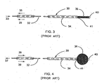
- sheathless vascular filter devices are operated by a "push-pull" mechanism that is also typical of other expandable braid devices, as shown in FIGS. 3 and 4.
- Prior art expandable braid device 30 includes core wire 32 and tubular shaft 34 slidably disposed there about.
- Tubular braid 36 surrounds core wire 32 and has a braid distal end fixed to core wire distal end 40 and a braid proximal end fixed to shaft distal end 41.
- core wire 32 is pulled and shaft 34 is pushed, as shown by arrows 37 and 39 respectively in FIG. 4.
- the relative displacement of core wire 32 and shaft 34 moves the ends of braid 36 towards each other, forcing the middle region of braid 36 to expand.
- core wire 32 is pushed and shaft 34 is pulled, as shown by arrows 33 and 35 respectively in FIG. 3. This reverse manipulation draws the ends of braid 36 apart, pulling the middle region of braid 36 radially inward toward core wire 32.
- FIG. 11 illustrates an embodiment not being part of the invention in which filter guidewire 50 also incorporates steerable guidewire 55, as described above with respect to filter guidewire 51.
- filter guidewire 50 the mounting arrangement of filter 25 is reversed with respect to filter guidewire 20, such that filter distal end 27 is slidably mounted around and adjacent to the distal end of guidewire 55, and filter proximal end 29 is fixed to guidewire 55.
- Elongate tubular actuator 60 is slidingly and coaxially disposed around guidewire 55 proximal to filter 25.
- the elongate tubular actuator 60 may be used as an alternative to actuator 62 shown in Figs.7 to 9.
- Link 65 movably extends through opening 66 in filter 25 adjacent filter proximal end 29 and connects the distal end of actuator 60 to filter distal end 2 7. Opening 66 is one of the inlet openings of filter 25, however any opening large enough to slidably pass link 65 will suffice. For example, a standard or over-sized pore in filter 25 may permit link 65 to extend there through.
- Actuator 60 can be made from thin walled metal tubing, such as stainless steel hypodermic tubing, or more preferably, polyimide tubing.
- actuator 60 should have an outside diameter of 0.014 inch (0.36 mm) or less so that filter guidewire 50 can be slidably received within the guidewire lumen of the catheter.
- Link 65 is preferably a thin wire, such as stainless steel, measuring approximately 0.002 to 0.008 inch (0.05 to 0.20 mm) in diameter, most preferably 0.006 inch (0.15 mm).
- link 65 may be a non-metallic filament capable of pushing and/or pulling filter distal end 27.
- Transformation of filter 25 from the deployed configuration to the collapsed configuration is achieved by manipulating the proximal ends of guidewire 55 and actuator 60 as follows. Pushing actuator 60 distally while pulling guidewire 55 proximally causes link 65 to advance into filter 25 and displace filter distal end 27 distally along guidewire 55. The movement of filter distal end 27 away from filter proximal end 29, which is fixed to guidewire 55, forces filter 25 to collapse around guidewire 55 to a lower profile that is suitable for introduction to or withdrawal from the patient. The distal end of actuator 60 is spaced proximally from filter proximal end 29 a distance sufficient to permit a range of motion of actuator 60 without contacting filter proximal end 29. In this embodiment wherein filter 25 is self-expanding, link 65 is placed under compression loading to collapse filter 25, and thus link 65 is also referred to as a push rod.
- filter 25 may be self-collapsing, wherein its shape memory is to return to the collapsed configuration.
- deployment of filter 25 is achieved and maintained by pulling actuator 60 proximally while pushing guidewire 55 distally, which action draws filter distal end 27 and filter proximal end 29 towards each other and forces expansion of filter 25.
- link 65 is placed under tension loading to deplov filter 25.
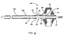
- FIG. 6 depicts filter guidewire 56, which is an embodiment not being part of the invention, and wherein self-expanding filter 25 is arranged over guidewire 55 similarly to filter guidewire 50, described above.
- actuator 62 is a short ring slidingly and coaxially disposed around guidewire 55 proximal to filter 25.
- Link 70 movably extends through opening 78 within filter proximal end 29 and connects actuator 62 to filter distal end 2 7.
- Link 70 includes link proximal segment 72 and link distal segment 74.
- Link distal segment 74 is a tubular element that is fixed to filter distal end 27 and is slidingly disposed around guidewire 55 within filter 25.
- Link distal segment 74 is made from thin walled tubing, preferably polyimide.
- Link proximal segment 72 is comparable to the wire of link 65, and extends from an attachment point on actuator 62 into filter 25 to connect with link distal segment 74.
- joint 76 attaches filter proximal end 29 to guidewire 55, and includes opening 78, which guides link proximal segment 72 which is slidably disposed there through.
- Joint 76 may be made from any suitable fastening material such as adhesive, braze alloy, or preferably, solder.
- opening 78 is formed by a short section of thin walled polyimide tubing (not shown), which is incorporated into joint 76 within filter proximal end 29.
- opening 78 can be formed by including a removable mandrel, such as a stainless steel wire coated with polytetrafluoroethylene (PTFE), in joint 76 during its formation.
- PTFE polytetrafluoroethylene
- Elongate hollow rod 180 is slidably and removably disposed along guidewire 55 such that rod distal end 182 is engageable with actuator 62.
- rod distal end 182 may be used as an alternative to rod 180 shown Fig.7.
- Rod distal end 182 is an over-sized section of rod 180 such that it will slidably fit over at least a proximal portion of actuator 62, as shown in the alternate position in FIG. 6.
- the engaged combination of rod 180 and actuator 62 can apply distally directed force to link 70, similarly to the operation of elongate actuator 60 in guidewire filter 50.
- rod distal end 182 can be an unexpanded end of rod 180, similar to rod distal end 82 of rod 80, in which case rod distal end 182 may simply abut actuator 62 without extending there over.
- Optional stop 79 may be fixed to guidewire 55 proximal to actuator 62. Stop 79 can prevent interventional catheters positioned on guidewire 55 from engaging and moving actuator 62 and unintentionally collapsing filter 25. Stop 79 is smaller in diameter than actuator 62 such that rod 180 may be sized to slide over stop 79 and engage actuator 62, as shown in the alternate position in FIG. 6.
- filter guidewire 56 There are advantages to filter guidewire 56, besides the more habitual "reverse" push-pull action that it shares with filter guidewire 50, described above.
- guidewire 55 In filter guidewire 50, guidewire 55 must be small enough to fit slidably inside of actuator 60 which, in turn, must fit inside the guidewire lumen of a therapeutic catheter.
- guidewire 55 In filter guidewire 56, guidewire 55 can be large enough to fill the guidewire lumen of the same sized therapeutic catheter, because elongate rod 180 can be removed and replaced with the catheter.
- a larger, more standard sized guidewire can be included in the filter device, with the attendant performance advantages that accompany such an increase in size.
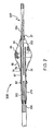
- FIG. 7 depicts filter guidewire 150, a first embodiment of the invention.
- Filter guidewire 150 incorporates filter 25 and link 65 from filter guidewire 50, actuator 62 with hollow rod 180 from filter guidewire 56, and proximal assist spring 87 from filter guidewire 85.
- Actuator 62 is slidingly disposed about the guidewire, and link 65 extends through opening 78 to connect actuator 62 to filter distal end 27.
- Removable rod 180 abuts actuator 62 and can advance it against spring 87 to collapse filter 25.
- the guidewire of filter guidewire 150 comprises disconnected guidewire proximal and distal shafts 155,157.
- Filter proximal end 29 is fixed near the distal end of proximal shaft 155 and filter distal end 27 is fixed near the proximal end of distal shaft 157. As shown in FIG. 7, more than one link 65 may be desirable in bridging the gap between proximal and Distal shafts 155,157. As filter ends 27, 29 separate, links 65 are drawn into filter 25 through openings 78. The combination of filter 25 and multiple links 65 can provide a relatively uniform transition from proximal shaft 155 to distal shaft 157.
- filter guidewire 150 One benefit of the structure of filter guidewire 150 is that guidewire distal shaft 157 extending from filter distal end 27 forms a fixed length tip of the device, regardless of the configuration of filter 25. Conversely, in filter guidewire 56, the tip length changes as filter distal end 27 slides along guidewire 55 during transformation of filter 25 between open and collapsed configurations.
- the variable tip length of filter guidewire 56 provides a short tip when filter 25 is collapsed, as during advancement of filter 25 to treatment area 15, but the tip needs to lengthen distally of treatment area 15, if possible, during deployment of filter 25.
- the distal tip position of the device remains fixed relative to the treatment area.
- FIG. 8 depicts filter guidewire 256, which is an alternative version of the first embodiment of the invention.
- Filter guidewire 256 incorporates filter 25, actuator 62, link 70 and removable hollow rod 180 (not shown) from filter guidewire 56, and proximal assist spring 87 from filter guidewire 85.
- Actuator 62 is slidingly disposed about guidewire proximal shaft 256, and link 70 extends through opening 78 to connect actuator 62 to filter distal end 27.
- Rod 180 abuts actuator 62 and can advance it against spring 87 to collapse filter 25.
- This version slidingly joins the guidewire proximal and distal shafts within filter 25.
- Link 70 includes link proximal segment 72 and link distal segment 74.
- Link distal segment 74 is a tubular element that is fixed to filter distal end 27 and guidewire distal shaft 257. Within filter25, link distal segment 74 is slidingly disposed around the distal end of guidewire proximal shaft 255, which preferably has a stepped-down diameter. This alternative version maintains the beneficial fixed-length tip of the first embodiment of the invention.
- FIG. 9 depicts filter guidewire 356, which is another version of the first embodiment of the invention.
- Filter guidewire 356 incorporates filter 25, link 65 from filter guidewire 50, actuator 62 and hollow rod 180 (not shown) from filter guidewire 56, and proximal assist spring 87 from filter guidewire 85.
- actuator 62 is slidingly disposed about the guidewire, and link 65 extends through opening 78 to connect actuator 62 to filter distal end 27.
- Removable rod 180 (not shown) abuts actuator 62 and can advance it against spring 87 to collapse filter 25.
- the sliding connection between proximal and distal guidewire shafts in this version comprises tubular segment 374 and distal core segment 353.
- Tubular segment 374 is fixed to, and extends distally from proximal core wire 355, which is preferably stepped-down in diameter at distal end 352.
- Distal core segment 353 extends proximally from tubular tip member 354 of distal core wire 357, and is slidingly disposed within tubular segment 374. As filter ends 27, 29 separate, distal core segment 353 is partially withdrawn distally from tubular segment 374.
- Tubular segment 374 may be any suitable thin walled material, such as polyimide, or preferably nitinol.
- Distal core segment 353 may be tapered to avoid abrupt transitions in stiffness, especially adjacent the distal end of tubular segment 374. This second alternative version maintains the beneficial fixed-length tip of the fifth embodiment of the invention.
- the invention has been particularly shown and described with reference to the preferred embodiments thereof, it will be understood by those skilled in the art that various changes in form and detail may be made there in without departing from scope of the invention.
- the invention may be used in any intravascular treatment utilizing a guidewire where the possibility of loosening emboli may occur.
- the description herein illustrates angioplasty and stent placement procedures as significant applications, it should be understood that the present invention is in no way limited to those environments.
Claims (17)
- Zeitweilige Filtervorrichtung (150, 256, 356), umfassend:einen länglichen proximalen Führungsdrahtschaft (155, 255, 355) mit einem distalen Ende;einen relativ kurzen distalen Führungsdrahtschaft (157, 257, 357), der ein proximales Ende aufweist und zu dem proximalen Schaft (155, 255, 355) distal angeordnet und koaxial ausgerichtet ist;einen im Allgemeinen röhrenförmigen Filter (25), der koaxial um die proximalen und distalen Führungsdrahtschäfte angebracht ist, wobei der Filter (25) ein spitz zulaufendes distales Ende (27), das neben dem proximalen Ende des distalen Schafts (157, 257, 357) befestigt ist, und ein spitz zulaufendes proximales Ende (29), das neben dem distalen Ende des proximalen Schafts (155, 255, 355) befestigt ist, aufweist, wobei eine relative Längsbewegung zwischen den distalen und proximalen Enden des Filters (25) eine Umformung des Filters (25) zwischen einer zusammengedrückten Anordnung und einer offenen Anordnung begleitet;ein Stellglied (62), das verschiebbar längs dem proximalen Führungsdrahtschaft (155, 255, 355) angeordnet ist; undmindestens ein Verbindungsstück (65, 70), das verschiebbar durch mindestens eine Öffnung (78) in der Nähe des proximalen Filterendes (29) angeordnet ist und das Stellglied (62) mit dem distalen Ende (27) des Filters (25) verbindet.
- Zeitweilige Filtervorrichtung (150, 256, 356) nach Anspruch 1, wobei das mindestens eine Verbindungsstück (70) ein röhrenförmiges Distalsegment (74) umfasst, das verschiebbar um das distale Ende des proximalen Führungsdrahtschafts (255) angeordnet ist, wobei das röhrenförmige Distalsegment (74) in dem Filter (25) angeordnet ist.
- Zeitweilige Filtervorrichtung (150, 256, 356) nach Anspruch 1, wobei das distale Ende des proximalen Führungsdrahtschafts (255, 355) im Durchmesser reduziert ist.
- Zeitweilige Filtervorrichtung (150, 256, 356) nach Anspruch 1, wobei das proximale Ende (29) des Filters (25) um den proximalen Führungsdrahtschaft (155, 255, 355) durch ein Gelenk (76) befestigt ist, das mindestens eine Öffnung (78) durch dieses hindurch aufweist.
- Zeitweilige Filtervorrichtung (150, 256, 356) nach Anspruch 1, wobei ein flexibles röhrenförmiges Element (354) um den distalen Führungsdrahtschaft (157, 257, 357) befestigt ist.
- Zeitweilige Filtervorrichtung (150, 256, 356) nach Anspruch 1, wobei das Stellglied (60) eine längliche Röhre ist.
- Zeitweilige Filtervorrichtung (150, 256, 356) nach Anspruch 1, wobei das Stellglied (62) eine relative kurze Röhre oder ein Ring ist.
- Zeitweilige Filtervorrichtung (150, 256, 356) nach Anspruch 7, ferner umfassend einen länglichen hohlen Stab (180), der verschiebbar an dem proximalen Führungsdrahtschaft angeordnet ist, wobei der Stab ein distales Ende aufweist, das in das Stellglied (62) eingreifen kann.
- Zeitweilige Filtervorrichtung (150, 256, 356) nach Anspruch 7, ferner umfassend eine Schraubendruckfeder (87), die um den proximalen Führungsdrahtschaft (155, 255, 355) zwischen dem Stellglied (62) und dem proximalen Ende (29) des Filters (25) angeordnet ist, um zur Umformung des Filters (25) in die offene Anordnung beizutragen.
- Zeitweilige Filtervorrichtung (356), umfassend:einen länglichen proximalen Kerndraht (355) mit einem distalen Ende (352);einen distalen Kerndraht (357) mit einem proximalen Ende (353), wobei der Kerndraht (357) zu dem proximalen Kerndraht (355) distal angeordnet und koaxial ausgerichtet ist;ein röhrenförmiges Segment (374) mit einem distalen Ende, wobei das röhrenförmige Segment (374) fest um das distale Ende (352) des proximälen Kerndrahts (355) angeordnet ist und sich davon distal erstreckt, um verschiebbar in den proximalen Abschnitt (353) des distalen Kerndrahts (357) einzugreifen;einen im Allgemeinen röhrenförmigen Filter (25), der um den distalen Kerndraht (357) und das röhrenförmige Segment (374) angebracht ist, wobei der Filter (25) ein spitz zulaufendes distales Ende (27), das an dem distalen Kerndraht (357) befestigt ist, und ein spitz zulaufendes proximales Ende (29), das an dem röhrenförmigen Segment (374) befestigt ist, aufweist, wobei eine relative Längsbewegung zwischen den distalen und proximalen Enden des Filters (25) eine Umformung des Filters (25) zwischen einer zusammengedrückten Anordnung und einer offenen Anordnung begleitet;ein Stellglied (60, 62), das verschiebbar um das röhrenförmige Segment (374) proximal zu dem Filter (25) angeordnet ist; undein Verbindungsstück (65), das verschiebbar durch eine Öffnung (78) in der Nähe des proximalen Filterendes (29) angeordnet ist und das Stellglied (60, 62) mit dem distalen Ende (27) des Filters (25) verbindet.
- Zeitweilige Filtervorrichtung (356) nach Anspruch 10, wobei das distale Ende (352) des proximalen Kerndrahts (355) im Durchmesser reduziert ist.
- Zeitweilige Filtervorrichtung (356) nach Anspruch 10, wobei das proximale Ende (29) des Filters (25) um das röhrenförmige Segment (374) durch ein Gelenk (76) befestigt ist, das die Öffnung (78) durch dieses hindurch aufweist.
- Zeitweilige Filtervorrichtung (356) nach Anspruch 10, wobei ein flexibles röhrenförmiges Element (354) um den distalen Kerndraht (356) befestigt ist.
- Zeitweilige Filtervorrichtung (356) nach Anspruch 10, wobei das Stellglied (60) eine längliche Röhre ist.
- Zeitweilige Filtervorrichtung (356) nach Anspruch 10, wobei das Stellglied 62 eine relativ kurze Röhre oder ein Ring ist.
- Zeitweilige Filtervorrichtung (356) nach Anspruch 15, ferner umfassend einen länglichen hohlen Stab (180), der verschiebbar an dem proximalen Kerndraht (355) angeordnet ist, wobei der hohle Stab (180) ein distales Ende aufweist, das in das Stellglied (62) eingreifen kann.
- Zeitweilige Filtervorrichtung (356) nach Anspruch 15, ferner umfassend eine Schraubendruckfeder (87), die um das röhrenförmige Segment (374) zwischen dem Stellglied (62) und dem proximalen Ende (29) des Filters (25) angeordnet ist, um zur Umformung des Filters (25) in die offene Anordnung beizutragen.
Applications Claiming Priority (3)
| Application Number | Priority Date | Filing Date | Title |
|---|---|---|---|
| US09/918,441 US6818006B2 (en) | 2001-04-03 | 2001-07-27 | Temporary intraluminal filter guidewire |
| US918441 | 2001-07-27 | ||
| PCT/US2002/023831 WO2003011185A2 (en) | 2001-07-27 | 2002-07-25 | Temporary intraluminal filter guidewire |
Publications (2)
| Publication Number | Publication Date |
|---|---|
| EP1401354A2 EP1401354A2 (de) | 2004-03-31 |
| EP1401354B1 true EP1401354B1 (de) | 2005-11-23 |
Family
ID=25440387
Family Applications (1)
| Application Number | Title | Priority Date | Filing Date |
|---|---|---|---|
| EP02753417A Expired - Lifetime EP1401354B1 (de) | 2001-07-27 | 2002-07-25 | Zeitweiliger intraluminaler filterführungsdraht |
Country Status (6)
| Country | Link |
|---|---|
| US (2) | US6818006B2 (de) |
| EP (1) | EP1401354B1 (de) |
| JP (1) | JP2004536663A (de) |
| AT (1) | ATE310465T1 (de) |
| DE (1) | DE60207558T2 (de) |
| WO (1) | WO2003011185A2 (de) |
Families Citing this family (168)
| Publication number | Priority date | Publication date | Assignee | Title |
|---|---|---|---|---|
| WO1998039053A1 (en) | 1997-03-06 | 1998-09-11 | Scimed Life Systems, Inc. | Distal protection device and method |
| US7491216B2 (en) | 1997-11-07 | 2009-02-17 | Salviac Limited | Filter element with retractable guidewire tip |
| IL135463A0 (en) | 1997-11-07 | 2001-05-20 | Salviac Ltd | An embolic protection device |
| US7314477B1 (en) | 1998-09-25 | 2008-01-01 | C.R. Bard Inc. | Removable embolus blood clot filter and filter delivery unit |
| US6918921B2 (en) | 1999-05-07 | 2005-07-19 | Salviac Limited | Support frame for an embolic protection device |
| US6964672B2 (en) | 1999-05-07 | 2005-11-15 | Salviac Limited | Support frame for an embolic protection device |
| US8414543B2 (en) | 1999-10-22 | 2013-04-09 | Rex Medical, L.P. | Rotational thrombectomy wire with blocking device |
| US6402771B1 (en) | 1999-12-23 | 2002-06-11 | Guidant Endovascular Solutions | Snare |
| US6660021B1 (en) | 1999-12-23 | 2003-12-09 | Advanced Cardiovascular Systems, Inc. | Intravascular device and system |
| US6575997B1 (en) | 1999-12-23 | 2003-06-10 | Endovascular Technologies, Inc. | Embolic basket |
| US6695813B1 (en) | 1999-12-30 | 2004-02-24 | Advanced Cardiovascular Systems, Inc. | Embolic protection devices |
| US7918820B2 (en) | 1999-12-30 | 2011-04-05 | Advanced Cardiovascular Systems, Inc. | Device for, and method of, blocking emboli in vessels such as blood arteries |
| GB2369575A (en) | 2000-04-20 | 2002-06-05 | Salviac Ltd | An embolic protection system |
| US6964670B1 (en) | 2000-07-13 | 2005-11-15 | Advanced Cardiovascular Systems, Inc. | Embolic protection guide wire |
| US6506203B1 (en) | 2000-12-19 | 2003-01-14 | Advanced Cardiovascular Systems, Inc. | Low profile sheathless embolic protection system |
| US20020188314A1 (en) * | 2001-06-07 | 2002-12-12 | Microvena Corporation | Radiopaque distal embolic protection device |
| US7338510B2 (en) | 2001-06-29 | 2008-03-04 | Advanced Cardiovascular Systems, Inc. | Variable thickness embolic filtering devices and method of manufacturing the same |
| US6599307B1 (en) | 2001-06-29 | 2003-07-29 | Advanced Cardiovascular Systems, Inc. | Filter device for embolic protection systems |
| US6638294B1 (en) | 2001-08-30 | 2003-10-28 | Advanced Cardiovascular Systems, Inc. | Self furling umbrella frame for carotid filter |
| US6592606B2 (en) | 2001-08-31 | 2003-07-15 | Advanced Cardiovascular Systems, Inc. | Hinged short cage for an embolic protection device |
| US20040243170A1 (en) * | 2001-09-05 | 2004-12-02 | Mitta Suresh | Method and device for percutaneous surgical ventricular repair |
| US8262689B2 (en) | 2001-09-28 | 2012-09-11 | Advanced Cardiovascular Systems, Inc. | Embolic filtering devices |
| WO2003055412A2 (en) | 2001-12-21 | 2003-07-10 | Salviac Limited | A support frame for an embolic protection device |
| US7241304B2 (en) | 2001-12-21 | 2007-07-10 | Advanced Cardiovascular Systems, Inc. | Flexible and conformable embolic filtering devices |
| FR2850285B1 (fr) * | 2002-01-24 | 2006-06-30 | Medtronic Vascular Inc | Dispositif a fil de guidage pour la protection distale temporaire contre l'embolie. |
| US9204956B2 (en) | 2002-02-20 | 2015-12-08 | C. R. Bard, Inc. | IVC filter with translating hooks |
| US7192434B2 (en) * | 2002-03-08 | 2007-03-20 | Ev3 Inc. | Vascular protection devices and methods of use |
| US6773448B2 (en) | 2002-03-08 | 2004-08-10 | Ev3 Inc. | Distal protection devices having controllable wire motion |
| US7232452B2 (en) | 2002-07-12 | 2007-06-19 | Ev3 Inc. | Device to create proximal stasis |
| US8425549B2 (en) * | 2002-07-23 | 2013-04-23 | Reverse Medical Corporation | Systems and methods for removing obstructive matter from body lumens and treating vascular defects |
| US7252675B2 (en) | 2002-09-30 | 2007-08-07 | Advanced Cardiovascular, Inc. | Embolic filtering devices |
| US7331973B2 (en) | 2002-09-30 | 2008-02-19 | Avdanced Cardiovascular Systems, Inc. | Guide wire with embolic filtering attachment |
| US20040088000A1 (en) | 2002-10-31 | 2004-05-06 | Muller Paul F. | Single-wire expandable cages for embolic filtering devices |
| US7625389B2 (en) * | 2002-12-30 | 2009-12-01 | Boston Scientific Scimed, Inc. | Embolic protection device |
| JP2004261235A (ja) * | 2003-02-20 | 2004-09-24 | Kaneka Medix Corp | 医療用ワイヤー装置 |
| US7740644B2 (en) | 2003-02-24 | 2010-06-22 | Boston Scientific Scimed, Inc. | Embolic protection filtering device that can be adapted to be advanced over a guidewire |
| US8591540B2 (en) | 2003-02-27 | 2013-11-26 | Abbott Cardiovascular Systems Inc. | Embolic filtering devices |
| US20040193208A1 (en) * | 2003-03-27 | 2004-09-30 | Scimed Life Systems, Inc. | Radiopaque embolic protection filter membrane |
| US7331976B2 (en) | 2003-04-29 | 2008-02-19 | Rex Medical, L.P. | Distal protection device |
| US7604649B2 (en) | 2003-04-29 | 2009-10-20 | Rex Medical, L.P. | Distal protection device |
| DE602004018059D1 (de) * | 2003-04-30 | 2009-01-15 | Medtronic Vascular Inc | Perivaskulares Reparatursystem für Leckagen |
| US7892251B1 (en) | 2003-11-12 | 2011-02-22 | Advanced Cardiovascular Systems, Inc. | Component for delivering and locking a medical device to a guide wire |
| US7678129B1 (en) | 2004-03-19 | 2010-03-16 | Advanced Cardiovascular Systems, Inc. | Locking component for an embolic filter assembly |
| WO2005094283A2 (en) | 2004-03-25 | 2005-10-13 | Hauser David L | Vascular filter device |
| US8617234B2 (en) | 2004-05-25 | 2013-12-31 | Covidien Lp | Flexible vascular occluding device |
| US8628564B2 (en) | 2004-05-25 | 2014-01-14 | Covidien Lp | Methods and apparatus for luminal stenting |
| US20060206200A1 (en) | 2004-05-25 | 2006-09-14 | Chestnut Medical Technologies, Inc. | Flexible vascular occluding device |
| US8267985B2 (en) | 2005-05-25 | 2012-09-18 | Tyco Healthcare Group Lp | System and method for delivering and deploying an occluding device within a vessel |
| SG175723A1 (en) | 2004-05-25 | 2011-12-29 | Tyco Healthcare | Vascular stenting for aneurysms |
| CA2565106C (en) | 2004-05-25 | 2013-11-05 | Chestnut Medical Technologies, Inc. | Flexible vascular occluding device |
| US7749242B2 (en) * | 2004-06-21 | 2010-07-06 | Boston Scientific Scimed, Inc. | Expanding vaso-occlusive device |
| US7704267B2 (en) | 2004-08-04 | 2010-04-27 | C. R. Bard, Inc. | Non-entangling vena cava filter |
| EP1858437B1 (de) * | 2004-09-17 | 2011-08-24 | Nitinol Development Corporation | Formgedächtnis-dünnfilm-embolieschutzvorrichtung |
| US8795315B2 (en) | 2004-10-06 | 2014-08-05 | Cook Medical Technologies Llc | Emboli capturing device having a coil and method for capturing emboli |
| US7794473B2 (en) | 2004-11-12 | 2010-09-14 | C.R. Bard, Inc. | Filter delivery system |
| US8267954B2 (en) | 2005-02-04 | 2012-09-18 | C. R. Bard, Inc. | Vascular filter with sensing capability |
| US8945169B2 (en) | 2005-03-15 | 2015-02-03 | Cook Medical Technologies Llc | Embolic protection device |
| US8221446B2 (en) | 2005-03-15 | 2012-07-17 | Cook Medical Technologies | Embolic protection device |
| US9259305B2 (en) | 2005-03-31 | 2016-02-16 | Abbott Cardiovascular Systems Inc. | Guide wire locking mechanism for rapid exchange and other catheter systems |
| CA2607580C (en) | 2005-05-12 | 2016-12-20 | C.R. Bard Inc. | Removable embolus blood clot filter |
| US20060271067A1 (en) * | 2005-05-24 | 2006-11-30 | C.R. Bard, Inc. | Laser-resistant surgical devices |
| US8273101B2 (en) | 2005-05-25 | 2012-09-25 | Tyco Healthcare Group Lp | System and method for delivering and deploying an occluding device within a vessel |
| CN101180006B (zh) * | 2005-05-25 | 2010-09-22 | 切斯纳特医药技术公司 | 用于在血管内输送和展开封堵器的系统 |
| US8672990B2 (en) * | 2005-05-27 | 2014-03-18 | Boston Scientific Scimed, Inc. | Fiber mesh controlled expansion balloon catheter |
| US8109962B2 (en) | 2005-06-20 | 2012-02-07 | Cook Medical Technologies Llc | Retrievable device having a reticulation portion with staggered struts |
| US7850708B2 (en) | 2005-06-20 | 2010-12-14 | Cook Incorporated | Embolic protection device having a reticulated body with staggered struts |
| US7771452B2 (en) | 2005-07-12 | 2010-08-10 | Cook Incorporated | Embolic protection device with a filter bag that disengages from a basket |
| US7766934B2 (en) | 2005-07-12 | 2010-08-03 | Cook Incorporated | Embolic protection device with an integral basket and bag |
| US8187298B2 (en) | 2005-08-04 | 2012-05-29 | Cook Medical Technologies Llc | Embolic protection device having inflatable frame |
| CA2616818C (en) | 2005-08-09 | 2014-08-05 | C.R. Bard, Inc. | Embolus blood clot filter and delivery system |
| US8377092B2 (en) | 2005-09-16 | 2013-02-19 | Cook Medical Technologies Llc | Embolic protection device |
| US7611524B1 (en) * | 2005-09-27 | 2009-11-03 | Lawrence Livermore National Security, Llc | Guide wire extension for shape memory polymer occlusion removal devices |
| US8632562B2 (en) | 2005-10-03 | 2014-01-21 | Cook Medical Technologies Llc | Embolic protection device |
| US8182508B2 (en) | 2005-10-04 | 2012-05-22 | Cook Medical Technologies Llc | Embolic protection device |
| US8252017B2 (en) | 2005-10-18 | 2012-08-28 | Cook Medical Technologies Llc | Invertible filter for embolic protection |
| US8216269B2 (en) | 2005-11-02 | 2012-07-10 | Cook Medical Technologies Llc | Embolic protection device having reduced profile |
| US20070112371A1 (en) * | 2005-11-14 | 2007-05-17 | Medtronic Vascular, Inc. | Embolic protection filter having compact collapsed dimensions and method of making same |
| US8152831B2 (en) | 2005-11-17 | 2012-04-10 | Cook Medical Technologies Llc | Foam embolic protection device |
| US9131999B2 (en) | 2005-11-18 | 2015-09-15 | C.R. Bard Inc. | Vena cava filter with filament |
| US20070156168A1 (en) * | 2005-12-29 | 2007-07-05 | Medtronic Vascular, Inc. | Polymer marker and retention bands |
| EP1981413B1 (de) | 2006-02-01 | 2014-11-12 | The Cleveland Clinic Foundation | Apparat zur erhöhung des blutflusses durch ein verlegtes blutgefäss |
| WO2007100556A1 (en) | 2006-02-22 | 2007-09-07 | Ev3 Inc. | Embolic protection systems having radiopaque filter mesh |
| US7846175B2 (en) | 2006-04-03 | 2010-12-07 | Medrad, Inc. | Guidewire and collapsable filter system |
| US7449002B1 (en) * | 2006-04-06 | 2008-11-11 | Pacesetter, Inc. | Steerable guide wire for delivering an implantable medical device |
| WO2007133366A2 (en) | 2006-05-02 | 2007-11-22 | C. R. Bard, Inc. | Vena cava filter formed from a sheet |
| US9326842B2 (en) | 2006-06-05 | 2016-05-03 | C. R . Bard, Inc. | Embolus blood clot filter utilizable with a single delivery system or a single retrieval system in one of a femoral or jugular access |
| US20080071307A1 (en) | 2006-09-19 | 2008-03-20 | Cook Incorporated | Apparatus and methods for in situ embolic protection |
| BRPI0717540A2 (pt) * | 2006-09-28 | 2013-10-22 | Heart Leaflet Technologies Inc | Instrumento de fornecimento para o fornecimento percutâneo de uma prótese |
| US8518054B2 (en) | 2006-11-21 | 2013-08-27 | Boston Scientific Scimed, Inc. | Medical retrieval devices |
| US8480702B2 (en) * | 2007-01-11 | 2013-07-09 | Covidien Lp | Convertible embolic protection devices and methods of use |
| US20080195141A1 (en) * | 2007-02-08 | 2008-08-14 | James Teague | Backstop protection device and method of using the same |
| US9901434B2 (en) | 2007-02-27 | 2018-02-27 | Cook Medical Technologies Llc | Embolic protection device including a Z-stent waist band |
| US20080255606A1 (en) * | 2007-04-16 | 2008-10-16 | Medtronic Vascular, Inc. | Filtering device for use within a body lumen |
| US9149610B2 (en) | 2007-05-31 | 2015-10-06 | Abbott Cardiovascular Systems Inc. | Method and apparatus for improving delivery of an agent to a kidney |
| US8216209B2 (en) | 2007-05-31 | 2012-07-10 | Abbott Cardiovascular Systems Inc. | Method and apparatus for delivering an agent to a kidney |
| US9364586B2 (en) | 2007-05-31 | 2016-06-14 | Abbott Cardiovascular Systems Inc. | Method and apparatus for improving delivery of an agent to a kidney |
| US9144509B2 (en) | 2007-05-31 | 2015-09-29 | Abbott Cardiovascular Systems Inc. | Method and apparatus for delivering an agent to a kidney |
| WO2008151204A1 (en) | 2007-06-04 | 2008-12-11 | Sequent Medical Inc. | Methods and devices for treatment of vascular defects |
| US7867273B2 (en) | 2007-06-27 | 2011-01-11 | Abbott Laboratories | Endoprostheses for peripheral arteries and other body vessels |
| US9744022B2 (en) | 2011-11-09 | 2017-08-29 | BiO2 Medical, Inc. | Detachment mechanism for a central venous access filter and method of use |
| US9138307B2 (en) | 2007-09-14 | 2015-09-22 | Cook Medical Technologies Llc | Expandable device for treatment of a stricture in a body vessel |
| US8419748B2 (en) | 2007-09-14 | 2013-04-16 | Cook Medical Technologies Llc | Helical thrombus removal device |
| US8252018B2 (en) | 2007-09-14 | 2012-08-28 | Cook Medical Technologies Llc | Helical embolic protection device |
| US8845710B2 (en) | 2007-11-30 | 2014-09-30 | Cook Medical Technologies Llc | Method and apparatus for introducing intraluminal prostheses |
| EP2279023B1 (de) | 2008-05-02 | 2020-12-02 | Sequent Medical, Inc. | Faserartige vorrichtungen zur behandlung von gefässdefekten |
| US9675482B2 (en) | 2008-05-13 | 2017-06-13 | Covidien Lp | Braid implant delivery systems |
| US20090292307A1 (en) * | 2008-05-22 | 2009-11-26 | Nasser Razack | Mechanical embolectomy device and method |
| US20100087850A1 (en) * | 2008-10-03 | 2010-04-08 | Nasser Razack | Mechanical Embolectomy Device and Method |
| CN102176873A (zh) | 2008-10-15 | 2011-09-07 | 捷迈有限公司 | 髓内钉 |
| US8388644B2 (en) | 2008-12-29 | 2013-03-05 | Cook Medical Technologies Llc | Embolic protection device and method of use |
| JP5685253B2 (ja) * | 2009-07-29 | 2015-03-18 | シー・アール・バード・インコーポレーテッドC R Bard Incorporated | 管状フィルター |
| US8696698B2 (en) | 2009-12-02 | 2014-04-15 | Surefire Medical, Inc. | Microvalve protection device and method of use for protection against embolization agent reflux |
| US9539081B2 (en) | 2009-12-02 | 2017-01-10 | Surefire Medical, Inc. | Method of operating a microvalve protection device |
| US8500775B2 (en) | 2009-12-02 | 2013-08-06 | Surefire Medical, Inc. | Protection device and method against embolization agent reflux |
| EP2539012B1 (de) | 2010-02-23 | 2018-01-24 | Covidien LP | Vorrichtungen zur gefäss-neukanalisierungen |
| US10076327B2 (en) | 2010-09-14 | 2018-09-18 | Evalve, Inc. | Flexible actuator mandrel for tissue apposition systems |
| US10321998B2 (en) | 2010-09-23 | 2019-06-18 | Transmural Systems Llc | Methods and systems for delivering prostheses using rail techniques |
| US9579193B2 (en) | 2010-09-23 | 2017-02-28 | Transmural Systems Llc | Methods and systems for delivering prostheses using rail techniques |
| US9770319B2 (en) | 2010-12-01 | 2017-09-26 | Surefire Medical, Inc. | Closed tip dynamic microvalve protection device |
| US10245049B2 (en) * | 2011-06-08 | 2019-04-02 | Cvdevices, Llc | Thrombus removal systems and devices and methods of using the same |
| US9549817B2 (en) | 2011-09-22 | 2017-01-24 | Transmural Systems Llc | Devices, systems and methods for repairing lumenal systems |
| US9089668B2 (en) | 2011-09-28 | 2015-07-28 | Surefire Medical, Inc. | Flow directional infusion device |
| CN103975101B (zh) | 2011-10-17 | 2016-09-07 | 后续医疗股份有限公司 | 编织机构及其使用方法 |
| WO2013119332A2 (en) | 2012-02-09 | 2013-08-15 | Stout Medical Group, L.P. | Embolic device and methods of use |
| US9089341B2 (en) | 2012-02-28 | 2015-07-28 | Surefire Medical, Inc. | Renal nerve neuromodulation device |
| US9358022B2 (en) | 2012-05-21 | 2016-06-07 | Noha, Llc | Clot removal device and method of using same |
| GB2503013A (en) * | 2012-06-14 | 2013-12-18 | Cook Medical Technologies Llc | Vascular occlusion device |
| US9155647B2 (en) | 2012-07-18 | 2015-10-13 | Covidien Lp | Methods and apparatus for luminal stenting |
| US9301831B2 (en) | 2012-10-30 | 2016-04-05 | Covidien Lp | Methods for attaining a predetermined porosity of a vascular device |
| US9452070B2 (en) | 2012-10-31 | 2016-09-27 | Covidien Lp | Methods and systems for increasing a density of a region of a vascular device |
| US9943427B2 (en) | 2012-11-06 | 2018-04-17 | Covidien Lp | Shaped occluding devices and methods of using the same |
| US8784434B2 (en) | 2012-11-20 | 2014-07-22 | Inceptus Medical, Inc. | Methods and apparatus for treating embolism |
| US9157174B2 (en) | 2013-02-05 | 2015-10-13 | Covidien Lp | Vascular device for aneurysm treatment and providing blood flow into a perforator vessel |
| US9078658B2 (en) | 2013-08-16 | 2015-07-14 | Sequent Medical, Inc. | Filamentary devices for treatment of vascular defects |
| US9955976B2 (en) | 2013-08-16 | 2018-05-01 | Sequent Medical, Inc. | Filamentary devices for treatment of vascular defects |
| GB2517992A (en) * | 2013-09-09 | 2015-03-11 | Cook Medical Technologies Llc | Vena cava filter |
| US10238406B2 (en) | 2013-10-21 | 2019-03-26 | Inari Medical, Inc. | Methods and apparatus for treating embolism |
| AU2014356053A1 (en) * | 2013-11-28 | 2016-06-02 | Innoventions Ltd. | Filtration and entrapment apparatus and method of use |
| US9889031B1 (en) | 2014-03-25 | 2018-02-13 | Surefire Medical, Inc. | Method of gastric artery embolization |
| US9968740B2 (en) | 2014-03-25 | 2018-05-15 | Surefire Medical, Inc. | Closed tip dynamic microvalve protection device |
| US20170014115A1 (en) | 2014-03-27 | 2017-01-19 | Transmural Systems Llc | Devices and methods for closure of transvascular or transcameral access ports |
| US9629635B2 (en) | 2014-04-14 | 2017-04-25 | Sequent Medical, Inc. | Devices for therapeutic vascular procedures |
| WO2015184075A1 (en) | 2014-05-28 | 2015-12-03 | Stryker European Holdings I, Llc | Vaso-occlusive devices and methods of use |
| US9060777B1 (en) | 2014-05-28 | 2015-06-23 | Tw Medical Technologies, Llc | Vaso-occlusive devices and methods of use |
| CN111248966B (zh) * | 2014-08-14 | 2023-09-12 | 后续医疗股份有限公司 | 用于治疗血管缺损的丝状装置 |
| CN104688386B (zh) * | 2015-03-06 | 2017-10-13 | 杭州启明医疗器械有限公司 | 一种介入器械输送系统 |
| US20160287839A1 (en) | 2015-03-31 | 2016-10-06 | Surefire Medical, Inc. | Apparatus and Method for Infusing an Immunotherapy Agent to a Solid Tumor for Treatment |
| US10159490B2 (en) | 2015-05-08 | 2018-12-25 | Stryker European Holdings I, Llc | Vaso-occlusive devices |
| WO2017049003A1 (en) | 2015-09-15 | 2017-03-23 | Nasser Rafiee | Devices and methods for effectuating percutaneous glenn and fontan procedures |
| EP4233744A3 (de) | 2015-10-23 | 2023-11-01 | Inari Medical, Inc. | Vorrichtung zur intravaskulären behandlung eines gefässverschlusses |
| US11400263B1 (en) | 2016-09-19 | 2022-08-02 | Trisalus Life Sciences, Inc. | System and method for selective pressure-controlled therapeutic delivery |
| US10780250B1 (en) | 2016-09-19 | 2020-09-22 | Surefire Medical, Inc. | System and method for selective pressure-controlled therapeutic delivery |
| CN110312481B (zh) | 2016-10-24 | 2023-04-11 | 伊纳里医疗有限公司 | 用于治疗血管闭塞的装置和方法 |
| CN106510787B (zh) * | 2016-12-09 | 2019-05-10 | 国信医药科技(北京)有限公司 | 一种医疗器械技术服务用释放装置及其释放方法 |
| US10588636B2 (en) | 2017-03-20 | 2020-03-17 | Surefire Medical, Inc. | Dynamic reconfigurable microvalve protection device |
| US20210121280A1 (en) * | 2017-04-16 | 2021-04-29 | Sanford Health | Filter for Stent Retriever and Methods for Use Thereof |
| WO2019050765A1 (en) | 2017-09-06 | 2019-03-14 | Inari Medical, Inc. | HEMOSTATIC VALVES AND METHODS OF USE |
| US11154314B2 (en) | 2018-01-26 | 2021-10-26 | Inari Medical, Inc. | Single insertion delivery system for treating embolism and associated systems and methods |
| US11850398B2 (en) | 2018-08-01 | 2023-12-26 | Trisalus Life Sciences, Inc. | Systems and methods for pressure-facilitated therapeutic agent delivery |
| AU2019321256B2 (en) | 2018-08-13 | 2023-06-22 | Inari Medical, Inc. | System for treating embolism and associated devices and methods |
| US11433216B2 (en) | 2018-09-17 | 2022-09-06 | Seigla Medical, Inc. | Methods for fabricating medical devices and portions of medical devices |
| US11660420B2 (en) | 2018-09-17 | 2023-05-30 | Seigla Medical, Inc. | Catheters and related devices and methods of manufacture |
| US11547835B2 (en) | 2018-09-17 | 2023-01-10 | Seigla Medical, Inc. | Systems, methods and apparatus for guiding and supporting catheters and methods of manufacture |
| US11338117B2 (en) | 2018-10-08 | 2022-05-24 | Trisalus Life Sciences, Inc. | Implantable dual pathway therapeutic agent delivery port |
| CN113573765A (zh) | 2019-03-15 | 2021-10-29 | 后续医疗股份有限公司 | 用于治疗血管缺陷的丝装置 |
| CN113556985A (zh) | 2019-03-15 | 2021-10-26 | 后续医疗股份有限公司 | 用于治疗血管缺陷的丝装置 |
| EP3908208A4 (de) | 2019-03-15 | 2022-10-19 | Sequent Medical, Inc. | Fadenförmige vorrichtungen mit einer flexiblen verbindung zur behandlung von gefässdefekten |
| CN114845648A (zh) * | 2019-10-16 | 2022-08-02 | 伊纳里医疗有限公司 | 用于治疗血管闭塞的系统,装置,和方法 |
Family Cites Families (85)
| Publication number | Priority date | Publication date | Assignee | Title |
|---|---|---|---|---|
| US3966938A (en) * | 1972-10-26 | 1976-06-29 | Sandoz Ltd. | Treatment of thrombosis and the inhibition of blood platelet aggregation |
| US3996938A (en) | 1975-07-10 | 1976-12-14 | Clark Iii William T | Expanding mesh catheter |
| US4926858A (en) | 1984-05-30 | 1990-05-22 | Devices For Vascular Intervention, Inc. | Atherectomy device for severe occlusions |
| US4577631A (en) | 1984-11-16 | 1986-03-25 | Kreamer Jeffry W | Aneurysm repair apparatus and method |
| US4650466A (en) | 1985-11-01 | 1987-03-17 | Angiobrade Partners | Angioplasty device |
| US4799156A (en) * | 1986-10-01 | 1989-01-17 | Strategic Processing Corporation | Interactive market management system |
| US4875489A (en) | 1987-08-14 | 1989-10-24 | Advanced Cardiovascular Systems, Inc. | Extendable guidewire |
| US4937743A (en) * | 1987-09-10 | 1990-06-26 | Intellimed Corporation | Method and system for scheduling, monitoring and dynamically managing resources |
| US4922940A (en) * | 1989-07-31 | 1990-05-08 | Lewy Michael M | Invalid walker |
| FR2655533A1 (fr) | 1989-12-13 | 1991-06-14 | Lefebvre Jean Marie | Filtre-catheter. |
| CA2048307C (en) | 1990-08-14 | 1998-08-18 | Rolf Gunther | Method and apparatus for filtering blood in a blood vessel of a patient |
| US5265622A (en) | 1990-10-25 | 1993-11-30 | C. R. Bard, Inc. | Guidewire having radially expandable member and method for guiding and advancing a catheter using the same |
| ES2127756T3 (es) | 1991-06-17 | 1999-05-01 | Wilson Cook Medical Inc | Dispositivo de extraccion endoscopica con una estructura filar metalica compuesta. |
| JPH05133416A (ja) | 1991-11-07 | 1993-05-28 | Nippon Thompson Co Ltd | 防振性を有する直動案内ユニツト及びその製造方法 |
| US5381332A (en) * | 1991-12-09 | 1995-01-10 | Motorola, Inc. | Project management system with automated schedule and cost integration |
| US5291397A (en) * | 1991-12-20 | 1994-03-01 | Powell Roger A | Method for resource allocation and project control for the production of a product |
| EP0633798B1 (de) | 1992-03-31 | 2003-05-07 | Boston Scientific Corporation | Blutgefässfilter |
| US5569184A (en) | 1992-04-29 | 1996-10-29 | Cardiovascular Dynamics, Inc. | Delivery and balloon dilatation catheter and method of using |
| US5493490A (en) * | 1992-05-05 | 1996-02-20 | Clear With Computers, Inc. | Electronic proposal preparation system for selling vehicles |
| US5630840A (en) | 1993-01-19 | 1997-05-20 | Schneider (Usa) Inc | Clad composite stent |
| ES2166370T3 (es) | 1993-01-19 | 2002-04-16 | Schneider Usa Inc | Filamento implantable en material compuesto. |
| US5376094A (en) | 1993-08-19 | 1994-12-27 | Boston Scientific Corporation | Improved actuating handle with pulley system for providing mechanical advantage to a surgical working element |
| US5416694A (en) * | 1994-02-28 | 1995-05-16 | Hughes Training, Inc. | Computer-based data integration and management process for workforce planning and occupational readjustment |
| US5483022A (en) | 1994-04-12 | 1996-01-09 | Ventritex, Inc. | Implantable conductor coil formed from cabled composite wire |
| US5765418A (en) | 1994-05-16 | 1998-06-16 | Medtronic, Inc. | Method for making an implantable medical device from a refractory metal |
| US6123715A (en) | 1994-07-08 | 2000-09-26 | Amplatz; Curtis | Method of forming medical devices; intravascular occlusion devices |
| WO1996001591A1 (en) | 1994-07-08 | 1996-01-25 | Microvena Corporation | Method of forming medical devices; intravascular occlusion devices |
| US5802493A (en) * | 1994-12-07 | 1998-09-01 | Aetna Life Insurance Company | Method and apparatus for generating a proposal response |
| US5674258A (en) | 1995-03-08 | 1997-10-07 | Medtronic, Inc. | Packaged integrated accelerometer |
| US5664115A (en) * | 1995-06-07 | 1997-09-02 | Fraser; Richard | Interactive computer system to match buyers and sellers of real estate, businesses and other property using the internet |
| US6168604B1 (en) | 1995-10-06 | 2001-01-02 | Metamorphic Surgical Devices, Llc | Guide wire device for removing solid objects from body canals |
| US5715402A (en) * | 1995-11-09 | 1998-02-03 | Spot Metals Online | Method and system for matching sellers and buyers of spot metals |
| US5758328A (en) * | 1996-02-22 | 1998-05-26 | Giovannoli; Joseph | Computerized quotation system and method |
| US6088678A (en) * | 1996-04-09 | 2000-07-11 | Raytheon Company | Process simulation technique using benefit-trade matrices to estimate schedule, cost, and risk |
| US5794212A (en) * | 1996-04-10 | 1998-08-11 | Dominion Resources, Inc. | System and method for providing more efficient communications between energy suppliers, energy purchasers and transportation providers as necessary for an efficient and non-discriminatory energy market |
| US6096053A (en) | 1996-05-03 | 2000-08-01 | Scimed Life Systems, Inc. | Medical retrieval basket |
| US5935139A (en) | 1996-05-03 | 1999-08-10 | Boston Scientific Corporation | System for immobilizing or manipulating an object in a tract |
| US5995951A (en) * | 1996-06-04 | 1999-11-30 | Recipio | Network collaboration method and apparatus |
| GB2313933B (en) * | 1996-06-07 | 2000-06-28 | Edward Henry Mathews | A method of assisting the conducting of a research project |
| US5972019A (en) | 1996-07-25 | 1999-10-26 | Target Therapeutics, Inc. | Mechanical clot treatment device |
| US6066158A (en) | 1996-07-25 | 2000-05-23 | Target Therapeutics, Inc. | Mechanical clot encasing and removal wire |
| US5987464A (en) * | 1996-07-26 | 1999-11-16 | Schneider; Eric | Method and system for periodically updating data records having an expiry time |
| US6272467B1 (en) * | 1996-09-09 | 2001-08-07 | Spark Network Services, Inc. | System for data collection and matching compatible profiles |
| US5960407A (en) * | 1996-10-08 | 1999-09-28 | Vivona; Robert G. | Automated market price analysis system |
| US6014644A (en) * | 1996-11-22 | 2000-01-11 | Pp International, Inc. | Centrally coordinated communication systems with multiple broadcast data objects and response tracking |
| US5913202A (en) * | 1996-12-03 | 1999-06-15 | Fujitsu Limited | Financial information intermediary system |
| US5923552A (en) * | 1996-12-31 | 1999-07-13 | Buildnet, Inc. | Systems and methods for facilitating the exchange of information between separate business entities |
| US6391044B1 (en) | 1997-02-03 | 2002-05-21 | Angioguard, Inc. | Vascular filter system |
| US6152946A (en) | 1998-03-05 | 2000-11-28 | Scimed Life Systems, Inc. | Distal protection device and method |
| US6974469B2 (en) * | 1997-03-06 | 2005-12-13 | Scimed Life Systems, Inc. | Distal protection device and method |
| US5814064A (en) | 1997-03-06 | 1998-09-29 | Scimed Life Systems, Inc. | Distal protection device |
| US6112189A (en) * | 1997-03-19 | 2000-08-29 | Optimark Technologies, Inc. | Method and apparatus for automating negotiations between parties |
| WO1998047447A1 (en) | 1997-04-23 | 1998-10-29 | Dubrul William R | Bifurcated stent and distal protection system |
| US5911734A (en) | 1997-05-08 | 1999-06-15 | Embol-X, Inc. | Percutaneous catheter and guidewire having filter and medical device deployment capabilities |
| US6161099A (en) * | 1997-05-29 | 2000-12-12 | Muniauction, Inc. | Process and apparatus for conducting auctions over electronic networks |
| US6059814A (en) | 1997-06-02 | 2000-05-09 | Medtronic Ave., Inc. | Filter for filtering fluid in a bodily passageway |
| US5907490A (en) * | 1997-06-10 | 1999-05-25 | Electronic Data Systems Corporation | System and method for project management and assessment |
| US6058379A (en) * | 1997-07-11 | 2000-05-02 | Auction Source, L.L.C. | Real-time network exchange with seller specified exchange parameters and interactive seller participation |
| US6266659B1 (en) * | 1997-08-07 | 2001-07-24 | Uday P. Nadkarni | Skills database management system and method |
| US6049776A (en) * | 1997-09-06 | 2000-04-11 | Unisys Corporation | Human resource management system for staffing projects |
| DE69828634T2 (de) | 1997-11-03 | 2005-12-01 | C.R. Bard, Inc. | Führungsdraht für temporären blutfilter |
| US6131087A (en) * | 1997-11-05 | 2000-10-10 | The Planning Solutions Group, Inc. | Method for automatically identifying, matching, and near-matching buyers and sellers in electronic market transactions |
| IL135463A0 (en) | 1997-11-07 | 2001-05-20 | Salviac Ltd | An embolic protection device |
| AU2994499A (en) | 1998-03-04 | 1999-09-20 | Bioguide Consulting, Inc. | Guidewire filter device |
| US6092050A (en) * | 1998-03-09 | 2000-07-18 | Hard Dollar Corporation | Graphical computer system and method for financial estimating and project management |
| US6349238B1 (en) * | 1998-09-16 | 2002-02-19 | Mci Worldcom, Inc. | System and method for managing the workflow for processing service orders among a variety of organizations within a telecommunications company |
| US6230146B1 (en) * | 1998-09-18 | 2001-05-08 | Freemarkets, Inc. | Method and system for controlling closing times of electronic auctions involving multiple lots |
| US6189003B1 (en) * | 1998-10-23 | 2001-02-13 | Wynwyn.Com Inc. | Online business directory with predefined search template for facilitating the matching of buyers to qualified sellers |
| US6141653A (en) * | 1998-11-16 | 2000-10-31 | Tradeaccess Inc | System for interative, multivariate negotiations over a network |
| US6275812B1 (en) * | 1998-12-08 | 2001-08-14 | Lucent Technologies, Inc. | Intelligent system for dynamic resource management |
| US6171327B1 (en) | 1999-02-24 | 2001-01-09 | Scimed Life Systems, Inc. | Intravascular filter and method |
| US6277138B1 (en) * | 1999-08-17 | 2001-08-21 | Scion Cardio-Vascular, Inc. | Filter for embolic material mounted on expandable frame |
| AU3844799A (en) | 1999-05-07 | 2000-11-21 | Salviac Limited | A filter element with retractable guidewire tip |
| AU3844199A (en) | 1999-05-07 | 2000-11-21 | Salviac Limited | An embolic protection device |
| US6179859B1 (en) | 1999-07-16 | 2001-01-30 | Baff Llc | Emboli filtration system and methods of use |
| US6346116B1 (en) | 1999-08-03 | 2002-02-12 | Medtronic Ave, Inc. | Distal protection device |
| US6289340B1 (en) * | 1999-08-03 | 2001-09-11 | Ixmatch, Inc. | Consultant matching system and method for selecting candidates from a candidate pool by adjusting skill values |
| ES2209503T3 (es) * | 1999-08-27 | 2004-06-16 | Ev3 Inc. | Dispositivo medico plegable. |
| US6556976B1 (en) * | 1999-11-10 | 2003-04-29 | Gershman, Brickner And Bratton, Inc. | Method and system for e-commerce and related data management, analysis and reporting |
| WO2001045592A1 (en) | 1999-12-23 | 2001-06-28 | Percusurge, Inc. | Vascular filters with radiopaque markings |
| US6540722B1 (en) | 1999-12-30 | 2003-04-01 | Advanced Cardiovascular Systems, Inc. | Embolic protection devices |
| US6695813B1 (en) | 1999-12-30 | 2004-02-24 | Advanced Cardiovascular Systems, Inc. | Embolic protection devices |
| AU2001240079A1 (en) * | 2000-03-06 | 2001-09-17 | Wellogix Inc. | Method and process for providing relevant data, comparing proposal alternatives, and reconciling proposals, invoices, and purchase orders with actual costs in a workflow process |
| WO2001073551A2 (en) * | 2000-03-29 | 2001-10-04 | Nextset Software Inc. | System and method of providing an asynchronous interface between a client system and an enterprise javabeans-enabled server |
| US6558405B1 (en) * | 2000-08-29 | 2003-05-06 | Advanced Cardiovascular Systems, Inc. | Embolic filter |
-
2001
- 2001-07-27 US US09/918,441 patent/US6818006B2/en not_active Expired - Fee Related
-
2002
- 2002-07-25 DE DE60207558T patent/DE60207558T2/de not_active Expired - Fee Related
- 2002-07-25 EP EP02753417A patent/EP1401354B1/de not_active Expired - Lifetime
- 2002-07-25 WO PCT/US2002/023831 patent/WO2003011185A2/en active IP Right Grant
- 2002-07-25 JP JP2003516419A patent/JP2004536663A/ja not_active Ceased
- 2002-07-25 AT AT02753417T patent/ATE310465T1/de not_active IP Right Cessation
-
2004
- 2004-03-10 US US10/797,558 patent/US7066946B2/en not_active Expired - Fee Related
Also Published As
| Publication number | Publication date |
|---|---|
| DE60207558T2 (de) | 2006-08-10 |
| JP2004536663A (ja) | 2004-12-09 |
| DE60207558D1 (de) | 2005-12-29 |
| ATE310465T1 (de) | 2005-12-15 |
| WO2003011185A3 (en) | 2003-12-18 |
| EP1401354A2 (de) | 2004-03-31 |
| WO2003011185A2 (en) | 2003-02-13 |
| US20040220609A1 (en) | 2004-11-04 |
| US6818006B2 (en) | 2004-11-16 |
| US20020143360A1 (en) | 2002-10-03 |
| US7066946B2 (en) | 2006-06-27 |
Similar Documents
| Publication | Publication Date | Title |
|---|---|---|
| EP1401354B1 (de) | Zeitweiliger intraluminaler filterführungsdraht | |
| EP1371344B1 (de) | Temporärer Intraluminalfilter | |
| EP1489994B1 (de) | Führungsdrahtapparat zur verhinderung distaler atheroembolisation | |
| US7044958B2 (en) | Temporary device for capturing embolic material | |
| EP1316292B1 (de) | Vorrichtung für einen temporären intraluminalen Schutz | |
| EP1247501B1 (de) | Entfernbares vaskuläres Filtersystem mit variablem Durchmesser | |
| US6706055B2 (en) | Guidewire apparatus for temporary distal embolic protection | |
| EP1459703B1 (de) | Temporäre distale Embolieschutzvorrichtung | |
| US7354445B2 (en) | Embolic containment system with asymmetric frictional control | |
| US20070149996A1 (en) | Low profile filter | |
| US20030060843A1 (en) | Vascular filter system with encapsulated filter | |
| AU2003201279A1 (en) | Low profile vascular filter system |
Legal Events
| Date | Code | Title | Description |
|---|---|---|---|
| PUAI | Public reference made under article 153(3) epc to a published international application that has entered the european phase |
Free format text: ORIGINAL CODE: 0009012 |
|
| 17P | Request for examination filed |
Effective date: 20030925 |
|
| AK | Designated contracting states |
Kind code of ref document: A2 Designated state(s): AT BE BG CH CY CZ DE DK EE ES FI FR GB GR IE IT LI LU MC NL PT |
|
| RBV | Designated contracting states (corrected) |
Designated state(s): AT BE BG CH CY CZ DE DK EE ES FI FR GB GR IE IT LI LU MC NL PT SE SK TR |
|
| 17Q | First examination report despatched |
Effective date: 20040622 |
|
| GRAP | Despatch of communication of intention to grant a patent |
Free format text: ORIGINAL CODE: EPIDOSNIGR1 |
|
| RIN1 | Information on inventor provided before grant (corrected) |
Inventor name: BRIGHTBILL, JERRY Inventor name: STRICKLER, PETER, G. Inventor name: DOUK, NAREAK Inventor name: RAFIEE, NASSER Inventor name: BRIN, DAVID, S. |
|
| GRAS | Grant fee paid |
Free format text: ORIGINAL CODE: EPIDOSNIGR3 |
|
| GRAA | (expected) grant |
Free format text: ORIGINAL CODE: 0009210 |
|
| AK | Designated contracting states |
Kind code of ref document: B1 Designated state(s): AT BE BG CH CY CZ DE DK EE ES FI FR GB GR IE IT LI LU MC NL PT SE SK TR |
|
| PG25 | Lapsed in a contracting state [announced via postgrant information from national office to epo] |
Ref country code: SK Free format text: LAPSE BECAUSE OF FAILURE TO SUBMIT A TRANSLATION OF THE DESCRIPTION OR TO PAY THE FEE WITHIN THE PRESCRIBED TIME-LIMIT Effective date: 20051123 Ref country code: NL Free format text: LAPSE BECAUSE OF FAILURE TO SUBMIT A TRANSLATION OF THE DESCRIPTION OR TO PAY THE FEE WITHIN THE PRESCRIBED TIME-LIMIT Effective date: 20051123 Ref country code: CZ Free format text: LAPSE BECAUSE OF FAILURE TO SUBMIT A TRANSLATION OF THE DESCRIPTION OR TO PAY THE FEE WITHIN THE PRESCRIBED TIME-LIMIT Effective date: 20051123 Ref country code: IT Free format text: LAPSE BECAUSE OF FAILURE TO SUBMIT A TRANSLATION OF THE DESCRIPTION OR TO PAY THE FEE WITHIN THE PRESCRIBED TIME-LIMIT;WARNING: LAPSES OF ITALIAN PATENTS WITH EFFECTIVE DATE BEFORE 2007 MAY HAVE OCCURRED AT ANY TIME BEFORE 2007. THE CORRECT EFFECTIVE DATE MAY BE DIFFERENT FROM THE ONE RECORDED. Effective date: 20051123 Ref country code: CH Free format text: LAPSE BECAUSE OF FAILURE TO SUBMIT A TRANSLATION OF THE DESCRIPTION OR TO PAY THE FEE WITHIN THE PRESCRIBED TIME-LIMIT Effective date: 20051123 Ref country code: FI Free format text: LAPSE BECAUSE OF FAILURE TO SUBMIT A TRANSLATION OF THE DESCRIPTION OR TO PAY THE FEE WITHIN THE PRESCRIBED TIME-LIMIT Effective date: 20051123 Ref country code: LI Free format text: LAPSE BECAUSE OF FAILURE TO SUBMIT A TRANSLATION OF THE DESCRIPTION OR TO PAY THE FEE WITHIN THE PRESCRIBED TIME-LIMIT Effective date: 20051123 Ref country code: BE Free format text: LAPSE BECAUSE OF FAILURE TO SUBMIT A TRANSLATION OF THE DESCRIPTION OR TO PAY THE FEE WITHIN THE PRESCRIBED TIME-LIMIT Effective date: 20051123 Ref country code: AT Free format text: LAPSE BECAUSE OF FAILURE TO SUBMIT A TRANSLATION OF THE DESCRIPTION OR TO PAY THE FEE WITHIN THE PRESCRIBED TIME-LIMIT Effective date: 20051123 |
|
| REG | Reference to a national code |
Ref country code: GB Ref legal event code: FG4D |
|
| RIN1 | Information on inventor provided before grant (corrected) |
Inventor name: BRIN, DAVID, S. Inventor name: RAFIEE, NASSER Inventor name: BRIGHTBILL, JERRY Inventor name: STRICKLER, PETER, G. Inventor name: DOUK, NAREAK |
|
| REG | Reference to a national code |
Ref country code: CH Ref legal event code: EP |
|
| REF | Corresponds to: |
Ref document number: 60207558 Country of ref document: DE Date of ref document: 20051229 Kind code of ref document: P |
|
| REG | Reference to a national code |
Ref country code: IE Ref legal event code: FG4D |
|
| PG25 | Lapsed in a contracting state [announced via postgrant information from national office to epo] |
Ref country code: DK Free format text: LAPSE BECAUSE OF FAILURE TO SUBMIT A TRANSLATION OF THE DESCRIPTION OR TO PAY THE FEE WITHIN THE PRESCRIBED TIME-LIMIT Effective date: 20060223 Ref country code: SE Free format text: LAPSE BECAUSE OF FAILURE TO SUBMIT A TRANSLATION OF THE DESCRIPTION OR TO PAY THE FEE WITHIN THE PRESCRIBED TIME-LIMIT Effective date: 20060223 Ref country code: GR Free format text: LAPSE BECAUSE OF FAILURE TO SUBMIT A TRANSLATION OF THE DESCRIPTION OR TO PAY THE FEE WITHIN THE PRESCRIBED TIME-LIMIT Effective date: 20060223 Ref country code: BG Free format text: LAPSE BECAUSE OF FAILURE TO SUBMIT A TRANSLATION OF THE DESCRIPTION OR TO PAY THE FEE WITHIN THE PRESCRIBED TIME-LIMIT Effective date: 20060223 |
|
| PG25 | Lapsed in a contracting state [announced via postgrant information from national office to epo] |
Ref country code: ES Free format text: LAPSE BECAUSE OF FAILURE TO SUBMIT A TRANSLATION OF THE DESCRIPTION OR TO PAY THE FEE WITHIN THE PRESCRIBED TIME-LIMIT Effective date: 20060306 |
|
| PG25 | Lapsed in a contracting state [announced via postgrant information from national office to epo] |
Ref country code: PT Free format text: LAPSE BECAUSE OF FAILURE TO SUBMIT A TRANSLATION OF THE DESCRIPTION OR TO PAY THE FEE WITHIN THE PRESCRIBED TIME-LIMIT Effective date: 20060424 |
|
| NLV1 | Nl: lapsed or annulled due to failure to fulfill the requirements of art. 29p and 29m of the patents act | ||
| REG | Reference to a national code |
Ref country code: CH Ref legal event code: PL |
|
| ET | Fr: translation filed | ||
| PG25 | Lapsed in a contracting state [announced via postgrant information from national office to epo] |
Ref country code: IE Free format text: LAPSE BECAUSE OF NON-PAYMENT OF DUE FEES Effective date: 20060725 |
|
| PG25 | Lapsed in a contracting state [announced via postgrant information from national office to epo] |
Ref country code: MC Free format text: LAPSE BECAUSE OF NON-PAYMENT OF DUE FEES Effective date: 20060731 |
|
| PLBE | No opposition filed within time limit |
Free format text: ORIGINAL CODE: 0009261 |
|
| STAA | Information on the status of an ep patent application or granted ep patent |
Free format text: STATUS: NO OPPOSITION FILED WITHIN TIME LIMIT |
|
| 26N | No opposition filed |
Effective date: 20060824 |
|
| REG | Reference to a national code |
Ref country code: IE Ref legal event code: MM4A |
|
| PG25 | Lapsed in a contracting state [announced via postgrant information from national office to epo] |
Ref country code: EE Free format text: LAPSE BECAUSE OF FAILURE TO SUBMIT A TRANSLATION OF THE DESCRIPTION OR TO PAY THE FEE WITHIN THE PRESCRIBED TIME-LIMIT Effective date: 20051123 |
|
| PG25 | Lapsed in a contracting state [announced via postgrant information from national office to epo] |
Ref country code: TR Free format text: LAPSE BECAUSE OF FAILURE TO SUBMIT A TRANSLATION OF THE DESCRIPTION OR TO PAY THE FEE WITHIN THE PRESCRIBED TIME-LIMIT Effective date: 20051123 Ref country code: LU Free format text: LAPSE BECAUSE OF NON-PAYMENT OF DUE FEES Effective date: 20060725 |
|
| PGFP | Annual fee paid to national office [announced via postgrant information from national office to epo] |
Ref country code: DE Payment date: 20080731 Year of fee payment: 7 |
|
| PG25 | Lapsed in a contracting state [announced via postgrant information from national office to epo] |
Ref country code: CY Free format text: LAPSE BECAUSE OF FAILURE TO SUBMIT A TRANSLATION OF THE DESCRIPTION OR TO PAY THE FEE WITHIN THE PRESCRIBED TIME-LIMIT Effective date: 20051123 |
|
| PGFP | Annual fee paid to national office [announced via postgrant information from national office to epo] |
Ref country code: FR Payment date: 20080707 Year of fee payment: 7 |
|
| PGFP | Annual fee paid to national office [announced via postgrant information from national office to epo] |
Ref country code: GB Payment date: 20080616 Year of fee payment: 7 |
|
| GBPC | Gb: european patent ceased through non-payment of renewal fee |
Effective date: 20090725 |
|
| REG | Reference to a national code |
Ref country code: FR Ref legal event code: ST Effective date: 20100331 |
|
| PG25 | Lapsed in a contracting state [announced via postgrant information from national office to epo] |
Ref country code: FR Free format text: LAPSE BECAUSE OF NON-PAYMENT OF DUE FEES Effective date: 20090731 |
|
| PG25 | Lapsed in a contracting state [announced via postgrant information from national office to epo] |
Ref country code: GB Free format text: LAPSE BECAUSE OF NON-PAYMENT OF DUE FEES Effective date: 20090725 |
|
| PG25 | Lapsed in a contracting state [announced via postgrant information from national office to epo] |
Ref country code: DE Free format text: LAPSE BECAUSE OF NON-PAYMENT OF DUE FEES Effective date: 20100202 |