EP1401207A2 - Dispositif de traitement d'images, appareil de formation d'images, programme, et mémoire d'ordinateur la contenant - Google Patents
Dispositif de traitement d'images, appareil de formation d'images, programme, et mémoire d'ordinateur la contenant Download PDFInfo
- Publication number
- EP1401207A2 EP1401207A2 EP20030255858 EP03255858A EP1401207A2 EP 1401207 A2 EP1401207 A2 EP 1401207A2 EP 20030255858 EP20030255858 EP 20030255858 EP 03255858 A EP03255858 A EP 03255858A EP 1401207 A2 EP1401207 A2 EP 1401207A2
- Authority
- EP
- European Patent Office
- Prior art keywords
- image
- region
- size
- regions
- image processing
- Prior art date
- Legal status (The legal status is an assumption and is not a legal conclusion. Google has not performed a legal analysis and makes no representation as to the accuracy of the status listed.)
- Granted
Links
Images


Classifications
-
- H—ELECTRICITY
- H04—ELECTRIC COMMUNICATION TECHNIQUE
- H04N—PICTORIAL COMMUNICATION, e.g. TELEVISION
- H04N21/00—Selective content distribution, e.g. interactive television or video on demand [VOD]
- H04N21/40—Client devices specifically adapted for the reception of or interaction with content, e.g. set-top-box [STB]; Operations thereof
- H04N21/47—End-user applications
- H04N21/472—End-user interface for requesting content, additional data or services; End-user interface for interacting with content, e.g. for content reservation or setting reminders, for requesting event notification, for manipulating displayed content
- H04N21/4728—End-user interface for requesting content, additional data or services; End-user interface for interacting with content, e.g. for content reservation or setting reminders, for requesting event notification, for manipulating displayed content for selecting a Region Of Interest [ROI], e.g. for requesting a higher resolution version of a selected region
-
- H—ELECTRICITY
- H04—ELECTRIC COMMUNICATION TECHNIQUE
- H04N—PICTORIAL COMMUNICATION, e.g. TELEVISION
- H04N19/00—Methods or arrangements for coding, decoding, compressing or decompressing digital video signals
- H04N19/50—Methods or arrangements for coding, decoding, compressing or decompressing digital video signals using predictive coding
- H04N19/503—Methods or arrangements for coding, decoding, compressing or decompressing digital video signals using predictive coding involving temporal prediction
-
- H—ELECTRICITY
- H04—ELECTRIC COMMUNICATION TECHNIQUE
- H04N—PICTORIAL COMMUNICATION, e.g. TELEVISION
- H04N19/00—Methods or arrangements for coding, decoding, compressing or decompressing digital video signals
- H04N19/60—Methods or arrangements for coding, decoding, compressing or decompressing digital video signals using transform coding
- H04N19/63—Methods or arrangements for coding, decoding, compressing or decompressing digital video signals using transform coding using sub-band based transform, e.g. wavelets
- H04N19/64—Methods or arrangements for coding, decoding, compressing or decompressing digital video signals using transform coding using sub-band based transform, e.g. wavelets characterised by ordering of coefficients or of bits for transmission
- H04N19/645—Methods or arrangements for coding, decoding, compressing or decompressing digital video signals using transform coding using sub-band based transform, e.g. wavelets characterised by ordering of coefficients or of bits for transmission by grouping of coefficients into blocks after the transform
-
- H—ELECTRICITY
- H04—ELECTRIC COMMUNICATION TECHNIQUE
- H04N—PICTORIAL COMMUNICATION, e.g. TELEVISION
- H04N19/00—Methods or arrangements for coding, decoding, compressing or decompressing digital video signals
- H04N19/70—Methods or arrangements for coding, decoding, compressing or decompressing digital video signals characterised by syntax aspects related to video coding, e.g. related to compression standards
-
- H—ELECTRICITY
- H04—ELECTRIC COMMUNICATION TECHNIQUE
- H04N—PICTORIAL COMMUNICATION, e.g. TELEVISION
- H04N21/00—Selective content distribution, e.g. interactive television or video on demand [VOD]
- H04N21/40—Client devices specifically adapted for the reception of or interaction with content, e.g. set-top-box [STB]; Operations thereof
- H04N21/45—Management operations performed by the client for facilitating the reception of or the interaction with the content or administrating data related to the end-user or to the client device itself, e.g. learning user preferences for recommending movies, resolving scheduling conflicts
- H04N21/462—Content or additional data management, e.g. creating a master electronic program guide from data received from the Internet and a Head-end, controlling the complexity of a video stream by scaling the resolution or bit-rate based on the client capabilities
- H04N21/4621—Controlling the complexity of the content stream or additional data, e.g. lowering the resolution or bit-rate of the video stream for a mobile client with a small screen
-
- H—ELECTRICITY
- H04—ELECTRIC COMMUNICATION TECHNIQUE
- H04N—PICTORIAL COMMUNICATION, e.g. TELEVISION
- H04N19/00—Methods or arrangements for coding, decoding, compressing or decompressing digital video signals
- H04N19/10—Methods or arrangements for coding, decoding, compressing or decompressing digital video signals using adaptive coding
Definitions
- the present invention relates to an image processing device, an image forming apparatus, a program, and a storing medium.
- Japanese Patent Application Laid-Open No. 2001-197500 discloses a technique in which an image is encoded by the tile so that when a user desires to decode a part of an image by encoding, without decoding an entire region of the image, it is sufficient to decode only a tile that includes a region that is desired to be decoded.
- an image processing device comprising:
- the position information changing means changes the position information of the plurality of regions to exclude, from the reduced image, a region that is among the plurality of regions and does not correspond to. the part of the contents of the original image.
- an image forming apparatus comprising:
- an image processing program comprising:
- a storing medium that stores an image processing program comprising:
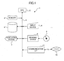
- FIG. 1 is a block diagram showing an electrical connection in an image processing device 1 according to the first embodiment of the present invention.
- the image processing device 1 may be a computer such as a personal computer that has a CPU 2 for performing various arithmetic operations and mainly controlling each unit of the image processing device 1, and a memory 3 constituted by various ROMs and RAMs.
- the CPU 2 and the memory 3 are connected by a bus 4.
- a magnetic storage device 5 such as a hard disk
- an input device 6 constituted by a mouse and a keyboard
- a displaying device 7 such as a LCD or a CRT
- a reading device 9 that reads information from a storing medium 8 such as an optical disc
- a predetermined communication interface 11 for performing communication with a network 10 such as the Internet.
- a storing medium 8 various media, for example, an optical disc such as a CD or a DVD, a magnetic optical disc, a flexible disc may be used.
- an optical disc drive, a magnetic optical disc drive, or a flexible disc drive may be used in accordance with a type of the storing medium 8.
- the magnetic storage device 5 stores an image processing program used for embodying the first embodiment of the present invention.
- This image processing program is read from the storing medium 8, or down-loaded from the network 10 such as the Internet so that the image processing program can be installed in the magnetic storage device 5.
- the image processing program By installing the image processing program to the magnetic storage device 5, an operation of the image processing device 1 is enabled.
- This image processing program may function as a part of specific application software, or may function on a predetermined operating system.
- FIG. 2 is a functional block of a process performed by the image forming apparatus 1.
- the image processing device 1 compresses and encodes image.data by using a JPEG2000 algorithm.
- JPEG2000 algorithm an image is divided into a plurality of small regions (tiles), and encoding is performed independently on each tile in a hierarchical fashion so that a code stream can be output from an encoding unit 22.
- an image dividing unit 21 divides image data into tiles, and outputs the divided image data to the encoding unit 22.
- the encoding unit 22 performs encoding process independently on each tile to compress and encode the image data so as to form the code stream.
- the encoding unit 22 may use a two-dimensional wavelet transformation and entropy-encoding (including arithmetic encoding).
- the encoding unit 22 uses the JPEG2000 algorithm.
- a size change setting unit 23 sets a change of an image size or a change of a region.
- a position information adding unit 24 adds position information or the like indicating a new position in the image to each tile of the code stream encoded by the encoding unit 22 so as to form a new code stream.
- An image of the newly formed code stream is an image whose size was changed from that of the original image, or an image in which an image region was moved from an original region position in the original image while all or a part of the contents of the original image are maintained.
- Each function of the dividing unit 21, the encoding unit 22, the size change setting unit 23, and the position information adding unit 24 is realized by a process that the CPU 2 executes based on the image processing program. Specifically, an image size described in a header part and/or an index that is position information indicating a position of a tile is changed so as to add the position information.
- the position information is information of an encoded data position compared to the input code stream.
- FIG. 3A shows an image 31 that is divided into 16 tiles T00 through T15 by the image dividing unit 21.
- a margin part is added to the image of FIG. 3A so as to form a code stream of an image 32 having a four times larger size than that of the image 31 with a size of a region of the original image 31 being maintained.
- the code stream of the image 32 that is changed from the image 31 so as to have the double size of the image 31.
- additional image tiles (regions) may be added to an original image so that a displayed region, for example can be increased.
- FIG. 4 shows one example of a data configuration of a code stream of the original image 31.
- FIG. 5 shows a data configuration of the code stream of the image 32 whose size is changed from the size of image 31.
- data of the tiles T04, and so on of the image 32 are not shown in the code stream of FIG. 5, but the tiles T04, and so on may exist in the code stream of FIG. 5.
- the data configuration of FIG. 5 is not shown in the code stream of FIG. 5, but the tiles T04, and so on may exist in the code stream of FIG. 5.
- an original image 33 shown in FIG. 6A is changed to an image 34 shown in FIG. 6B that has a size four times larger than that of the image 33.
- the size of the original image 31 is an integral multiple of a tile size
- by only changing an index of tiles it is possible to form a code stream of an image that has a four times larger size than that of an original image.
- an image before changing includes tiles (T04, T09, T14, and T19) having an incomplete size smaller than a complete tile size described in header information, only changing an index of tiles results in an expanded image different from a desired image.
- the encoding unit 22 specifies which tiles have incomplete seizes based on the header information, performs decoding on the tiles having incomplete sizes, edits the decoded image data , and create compressed and encoded data by using the JPEG2000 algorithm again.
- the tiles having incomplete sizes it is possible to create tiles (T04, T13, T22, and T31 in FIG. 6B) having complete sizes such that a part of each created tile includes image information of each original tile having the incomplete size.
- these tiles are also created.
- these tiles having incomplete sizes need to have header information describing these incomplete tile sizes, and may have or do not need to have image information.
- the encoding unit 22 may delete encoded data of the tiles having incomplete sizes T04, T09, T14, and T19 at a boundary part to create a code stream as shown in FIG. 7. In the changed code stream shown in FIG.
- a significance determining unit 25 may be added to the configuration of FIG. 2.
- the significance determining unit 25 determines whether or not a tile having an incomplete size includes significant image data. Specifically, the significance determining unit 25 determines whether or not the tile having an incomplete size only includes image data of a ground color of original document paper (original illustration paper or the like), and/or determines whether or not the tile having an incomplete size includes significant image data.
- the encoding unit 22 encodes (or re-encodes) the tiles having incomplete sizes such that image information of these tiles is maintained to perform size expanding.
- the encoding unit 22 performs encoding with the tile having an incomplete size being deleted as in the example shown in FIGS. 7 and 8.
- various pixel values may be assigned to a region that does not include the substantive contents of the tile having an incomplete size on the assumption that this tile has a complete size.
- a white color of the lowest pixel value (in a case of 8-bit image, 0 out of 0 through 255) is generally assigned to this region to perform encoding.
- a pixel value of a ground color of an original document may be assigned to this region.
- a ground color extracting unit 26 (refer to FIG. 10) (that is described later) detects a pixel value of a tile corresponding to a ground color part of the original document, and assigns this detected pixel value to the region of the tile corresponding to the ground color.
- the significance determining unit 25 may compare object code data amount of a tile with a predetermined threshold value, and determine that the tile does not include significant image data when the object code amount of the tile is smaller than the predetermined threshold value, and determines that the tile includes significant image data when the object code amount is larger than the predetermined threshold value.
- this determination by the significance determining unit 25 may be performed by using at least one of image information and code information in an input code stream.
- the determination by the significance determining unit 25 may be performed by using particular sub-band data of wavelet coefficients for the object tile.
- code data does not exist in the tile that does not include the original image data. Accordingly, the code amount of the expanded image is not so different from the code amount of the original image, so that the data amount can be made small.
- code data may be provided for such a blank tile that does not include the original image data in accordance with a necessity.
- various pixel values may be provided for the blank tile, but generally, a white color of the lowest pixel value (in a case of a 8-bit image data, 0 out of 0 through 255) may be provided for the blank tile to perform encoding.
- a pixel value of a ground color of the original document may be provided for the blank tile.
- a ground color code extracting unit 26 is provided to the configuration of FIG. 2.
- the code data of the tile having an incomplete size is decoded, and the number of pixels with respect to each pixel value of this tile is counted, and the most counted pixel value is determined to be the pixel value of the ground color of the original document.
- image data in which the pixel value of the ground color of the original document is provided to pixels for the tile having an incomplete size may be encoded again.
- the encoding unit 22 provides, to pixels for the tile having an incomplete size, a pixel value that is previously prepared as a pixel value of the ground color of the original document.
- a part of contents of an original image can be excluded from the original image so that a displayed region, for example, of the original image can be decreased.
- a reduced image 36 can be created from an original image 35 by rewriting position information of tiles such that original tiles T18 through T21 are changed to tiles T00 through T03, respectively, original tiles T26 through T29 are changed to tiles T04 through T07, respectively, original tiles T34 through T37 are changed to tiles T08 through T11, and original tiles T42 through T45 are changed to tiles T12 through T15.
- the encoding unit 22 may delete from a new code stream original tiles other than the tiles T18 through T21, T26 through T29, T34 through T37, and T42 through T45 of the original image 35.
- these original tiles other than the tiles T18 through T21, T26 through T29, T34 through T37, and T42 through T45 of the original image 35 may remain in a new code stream, and the position information adding unit 24 may add, to the new code stream of the new image 36, position information indication that these tiles are out of a range of the image 36. In this manner, by maintaining the information indicating that unnecessary tiles are out of the necessary range, it is also possible to create the original image 35 from the code stream of the new image 36.
- FIGS. 12A and 12B show this case.
- An upper left region 38 of an original image 37 (refer to FIG. 12A) is moved to a lower right position of an image 39 shown in FIG. 12B.
- Tiles other than tiles of the region 38 do not have to include code data, or may include code data for a predetermined pixel value as in the above-described (1).
- Code data for the moved region is created such that data of an original tile T00 is changed to data of a tile T10, data of an original tile T01 is changed to data of a tile T11, data of an original tile T04 is changed to data of a tile T14, and data of an original tile T05 is changed to data of a tile T15.
- code data is prepared for tiles T00, T01, T04, and T05, for example, code data corresponding to a ground color of an original document may be provided for these tiles T00, T01, T04, and T05.
- the ground color code extracting unit 26 may extract a pixel value of the ground color of the original document, or a predetermined pixel value that is previously prepared may be set as the pixel value of the ground color. Further alternatively, the data of the tiles T10, T11, T14, and T15 of the original image 37 may be set for the tiles T00, T01, T04, and T05 of the changed image 39.
- the image region 38 of the original image may be moved with all of data of the tiles T00 through T15 of the original image 37 being maintained such that the data of the tiles T00, T01, T04, and T05 of the original image are used as data of the tiles T00, T01, T04, and T05 of the changed image 39.
- the encoding unit 22 decodes such tiles having incomplete tile sizes, edits image data of these tiles, and encodes the edited image data again so as to create encoded data for a moved region of FIG. 13B.
- the encoding unit 22 may delete such tiles having incomplete sizes.
- code data for the original tile having an incomplete size may be used in an image after the region is moved, or code data corresponding to a ground color of an original document may be used in the image after the region is moved.
- the significance determining unit 25 may determine whether or not a tile having an incomplete size includes significant image data.
- the encoding unit 25 may decode the tile having an incomplete size, edits image data of the decoded tile, and compresses the edited image data to create code data of this tile. Meanwhile, when this tile having an incomplete size does not include significant image data, the encoding unit 25 may delete this tile as in the above-described (1).
- the above-described image processing device can be used in various fields.
- a layout of an image can be modified by expanding the image, moving a region in the image, and the like.
- size reduction is performed by deleting an edge part of the original image so that an image part for punch holes existing at the edge part of the original image can be deleted from the code data.
- an image processed by the image processing device 1 is not limited to a still image, but may be a moving image.
- a Motion-JPEG2000 algorithm is applied to the moving image.
- the image processing device may include a code data generating unit (not shown) that generates code data for the blank tile, and adds the generated code data to the code stream of the original image so that the image size expanding, the image size reducing, or the image region moving can be performed by using the code data for the blank tile.
- FIG. 14 is a block diagram showing an outline configuration of a digital copier 41 according to the second embodiment of the present invention.
- the digital copier 41 is an embodied example of an image forming apparatus according to the present invention.
- the digital copier 41 includes an image data reading unit 42 that functions as a scanner, an image data controlling unit 43, an image data processing unit 44 that is an embodied example of the image processing device according to the present invention, an image data storing unit 45, an image data writing unit 46 that has a printer engine, an operation panel 47, and a communication interface 48.
- the image data reading unit 46 performs a process of reading light reflected by an original document by using an optical system, performs a process of converting a light signal into an electric signal by using a CCD (Charge Coupled Device), and performs a process of converting an analog signal into a digital signal by using an A/D converter.
- CCD Charge Coupled Device
- the image data controlling unit 43 mainly controls each of these units.
- the image data controlling unit 43 has an interface with each of these units (e.g., one-to-one correspondence individual interface, or an interface via a common bus), and transfers image data between these units.
- the image processing unit 44 performs various processes on image data input to or output from the image processing unit 44 in accordance with control of the image data controlling unit 43.
- the image data storing unit 45 stores or reads image data input to or output from the image data storing unit 45 in accordance with control of the image data controlling unit 43.
- the image data writing unit 46 forms an image based on image data input to the image data writing unit 46 in accordance with control of the image data controlling unit 43.
- the image data writing unit 46 may use as a printing method an electrophotographic method, an inkjet method, a sublimation thermal transfer method, a silver-photographic method, a direct thermal recording method, and a melting thermal transfer method.
- the operation panel 47 includes various keys for receiving various operations from a user, and a liquid crystal display that displays various images and messages.
- the communication interface 48 performs transmission or reception of image data with an exterior personal computer by connecting the digital copier 41 with the exterior personal computer.
- the image processing unit 44 performs various processes on image data received from the image reading unit 42 or the communication interface 48. Particularly, by using the JPEG2000 algorithm, the image processing unit 44 compresses and encodes image data, changes an image size, and/or moves a region.
- FIG. 15 is a block diagram showing a hardware configuration in the image data processing unit 44.
- the hardware configuration is provided for compressing and encoding image data, changing an image size, and/or moving a region.
- a CPU 51, a ROM 52, and a RAM 53 are connected to each other by a bus 54.
- the ROM 52 is provided for storing the image processing program, and the CPU 51 uses the RAM 53 as a working area based on the image processing program to realize the functional blocks shown in FIGS. 9 and 10 so as to perform various processes such as the image size expanding and reducing, and moving of a region as described in the first embodiment of the present invention.
- the image data processing unit 44 may performs these processes directly on image data received from the image data reading unit 42 or the communication unit 48.
- the image data processing unit 42 may compress and encode image data received from the image data reading unit 42 or the communication interface 48 by using the JPEG2000 algorithm to form a code stream, then store the formed code stream in the image data storing unit 5, and read the stored code stream to perform various processes on the code stream in accordance with a necessity.
- FIG. 16 is a flowchart showing a process performed by a CPU of the image data controlling unit 43.
- the image data reading unit 42 or the communication interface 48 takes in image data at Step S2, and an image of the taken-in image data is displayed on the liquid crystal display of the operation panel 47 at Step S3.
- the user can view the displayed image, and select expanding or reducing of a size of the image at Step S4.
- the user selects the expanding of the image size (Yes at Step S5), the user selects, from an upper right position, an upper left position, a lower right position, a lower left position, a center position, and the like, a position at which the original image should be located in the expanded image (Yes at Step S6), and selects an expanding rate such as a 1.5-fold or 2-fold expansion rate at Step S7.
- the user selects the reducing of the image size (No at Step S5), the user selects, from an upper right position, an upper left position, a lower right position, a lower left position, a center position, and the like, a position (or a range) to which the image should be reduced from the original image (Yes at Step S8), and selects a reducing rate such as a 0.75-fold or 0.5-fold reduction rate (Yes at Step S9).
- the user selects a paper size (e.g., a B5 or A4 size)(Yes at Step S10), and presses down a predetermined execution button of the operation panel 7 (Yes at Step S11) so that the image data taken in at Step S2 can be compressed and encoded by the JPEG2000 algorithm to form a code stream.
- a process of the selected expanding or reducing is performed on this code stream at Step S12.
- the expanding or reducing process for the code stream is performed in the manner described in detail in the first embodiment of the present invention.
- a process of moving a region of the image can be performed on a code stream newly created by the expanding process.
- the image created by the expanding process is displayed on the liquid crystal display of the operation panel 47 at Step S14, and the user can view the displayed image.
- the user uses the operation panel 47 to further select the process of moving a region in the expanded image (Yes at Step S15)
- the user select a moving object region to be moved from an upper right region, an upper left region, a lower right region, and a lower left region, a center region, and the like of the expanded image, and selects a region to which the selected moving object region is moved, from the upper right region, the upper left region, the lower right region, the lower left region, the center region, and the like of the expanded image at Step S16.
- the region moving process is thereby performed at Step S17.
- the size change setting unit 23 performs setting for the image size change and/or the image region moving.
- the code stream created by the expanding or reducing process, and the image region moving process is stored in the image data storing unit 45 at Step S18. Meanwhile, when the user does not select the expanding or reducing of the image size (No at Step S4), the image data is compressed and encoded by the JPEG2000 algorithm without performing the expanding or reducing process to form a code stream, and the formed code stream is stored in the image data storing unit 45. The code stream formed in each case is sent to the image data writing unit 46 where the image of the code stream is formed on paper of the selected size at Step S19.
Landscapes
- Engineering & Computer Science (AREA)
- Multimedia (AREA)
- Signal Processing (AREA)
- Databases & Information Systems (AREA)
- Human Computer Interaction (AREA)
- Compression Of Band Width Or Redundancy In Fax (AREA)
- Editing Of Facsimile Originals (AREA)
- Image Processing (AREA)
- Record Information Processing For Printing (AREA)
Applications Claiming Priority (2)
| Application Number | Priority Date | Filing Date | Title |
|---|---|---|---|
| JP2002271186 | 2002-09-18 | ||
| JP2002271186A JP4135888B2 (ja) | 2002-09-18 | 2002-09-18 | 画像処理装置、画像処理方法、プログラム及び記憶媒体 |
Publications (3)
| Publication Number | Publication Date |
|---|---|
| EP1401207A2 true EP1401207A2 (fr) | 2004-03-24 |
| EP1401207A3 EP1401207A3 (fr) | 2004-05-26 |
| EP1401207B1 EP1401207B1 (fr) | 2008-01-09 |
Family
ID=31944545
Family Applications (1)
| Application Number | Title | Priority Date | Filing Date |
|---|---|---|---|
| EP20030255858 Expired - Lifetime EP1401207B1 (fr) | 2002-09-18 | 2003-09-18 | Dispositif de traitement d'images, appareil de formation d'images, programme, et mémoire d'ordinateur la contenant |
Country Status (4)
| Country | Link |
|---|---|
| US (1) | US7362904B2 (fr) |
| EP (1) | EP1401207B1 (fr) |
| JP (1) | JP4135888B2 (fr) |
| DE (1) | DE60318529T2 (fr) |
Cited By (1)
| Publication number | Priority date | Publication date | Assignee | Title |
|---|---|---|---|---|
| CN105141960A (zh) * | 2015-06-17 | 2015-12-09 | 西安空间无线电技术研究所 | 一种基于jpeg2000压缩码流进行信息传输的方法 |
Families Citing this family (8)
| Publication number | Priority date | Publication date | Assignee | Title |
|---|---|---|---|---|
| JP4812071B2 (ja) * | 2004-01-16 | 2011-11-09 | 株式会社リコー | 画像処理装置、画像処理方法、プログラム及び情報記録媒体 |
| JP2006086579A (ja) * | 2004-09-14 | 2006-03-30 | Ricoh Co Ltd | 画像処理装置、プログラム、及び記憶媒体 |
| JP4533273B2 (ja) * | 2005-08-09 | 2010-09-01 | キヤノン株式会社 | 画像処理装置及び画像処理方法、プログラム |
| US8135223B2 (en) * | 2007-03-16 | 2012-03-13 | Ricoh Company, Ltd. | Image processing apparatus and method of image processing |
| JP4907487B2 (ja) * | 2007-10-24 | 2012-03-28 | 株式会社リコー | 画像処理装置、画像処理方法及び該方法を実行させるためのプログラムを格納したコンピュータ読み取り可能な記録媒体 |
| JP4918026B2 (ja) * | 2007-12-21 | 2012-04-18 | 株式会社リコー | 画像符号化装置、画像符号化方法、コンピュータプログラム、及び、情報記録媒体 |
| JP5413080B2 (ja) * | 2009-09-15 | 2014-02-12 | 株式会社リコー | 画像処理装置及び画像処理方法 |
| WO2014050211A1 (fr) * | 2012-09-27 | 2014-04-03 | シャープ株式会社 | Programme, dispositif d'affichage, récepteur de télévision, procédé d'affichage et système d'affichage |
Citations (3)
| Publication number | Priority date | Publication date | Assignee | Title |
|---|---|---|---|---|
| WO1999049412A1 (fr) * | 1998-03-20 | 1999-09-30 | University Of Maryland | Procede et appareil de compression et de decompression d'images |
| EP0971544A2 (fr) * | 1998-07-03 | 2000-01-12 | Canon Kabushiki Kaisha | Une méthode et un procédé de codage d'images adaptés pour le décodage à différentes résolutions |
| EP1017238A1 (fr) * | 1997-09-19 | 2000-07-05 | Sharp Kabushiki Kaisha | Codeur d'images et decodeur d'images |
Family Cites Families (8)
| Publication number | Priority date | Publication date | Assignee | Title |
|---|---|---|---|---|
| JP3202433B2 (ja) | 1993-09-17 | 2001-08-27 | 株式会社リコー | 量子化装置、逆量子化装置及び画像処理装置並びに量子化方法、逆量子化方法及び画像処理方法 |
| JP2947085B2 (ja) | 1994-08-30 | 1999-09-13 | 日本電気株式会社 | 領域拡大を用いた画像の反復変換符号化装置及び復号装置 |
| JP3614361B2 (ja) | 1997-09-19 | 2005-01-26 | シャープ株式会社 | 画像復号装置 |
| JP2001189844A (ja) | 1999-12-28 | 2001-07-10 | Nec Corp | 情報挿入/検出方式 |
| JP2001258031A (ja) | 2000-03-08 | 2001-09-21 | Sony Corp | 信号処理方法、画像符号化装置及び画像復号装置 |
| US7006099B2 (en) * | 2000-08-15 | 2006-02-28 | Aware, Inc. | Cache system and method for generating uncached objects from cached and stored object components |
| US7206804B1 (en) * | 2000-11-10 | 2007-04-17 | Sharp Laboratories Of America, Inc. | Methods and systems for transmitting digital images |
| US7110608B2 (en) * | 2001-07-02 | 2006-09-19 | Canon Kabushiki Kaisha | Digital image compression |
-
2002
- 2002-09-18 JP JP2002271186A patent/JP4135888B2/ja not_active Expired - Fee Related
-
2003
- 2003-09-16 US US10/662,520 patent/US7362904B2/en not_active Expired - Fee Related
- 2003-09-18 DE DE2003618529 patent/DE60318529T2/de not_active Expired - Lifetime
- 2003-09-18 EP EP20030255858 patent/EP1401207B1/fr not_active Expired - Lifetime
Patent Citations (3)
| Publication number | Priority date | Publication date | Assignee | Title |
|---|---|---|---|---|
| EP1017238A1 (fr) * | 1997-09-19 | 2000-07-05 | Sharp Kabushiki Kaisha | Codeur d'images et decodeur d'images |
| WO1999049412A1 (fr) * | 1998-03-20 | 1999-09-30 | University Of Maryland | Procede et appareil de compression et de decompression d'images |
| EP0971544A2 (fr) * | 1998-07-03 | 2000-01-12 | Canon Kabushiki Kaisha | Une méthode et un procédé de codage d'images adaptés pour le décodage à différentes résolutions |
Non-Patent Citations (5)
| Title |
|---|
| ASKELÖF J ET AL: "Region of interest coding in JPEG 2000" SIGNAL PROCESSING. IMAGE COMMUNICATION, ELSEVIER SCIENCE PUBLISHERS, AMSTERDAM, NL, vol. 17, no. 1, January 2002 (2002-01), pages 105-111, XP004326801 ISSN: 0923-5965 * |
| GORMISH M J ET AL: "JPEG 2000: Overview, Architecture, and Applications" INTERNATIONAL CONFERENCE ON IMAGE PROCESSING (ICIP 2000); VANCOUVER, BC, CANADA, vol. 2, 10 September 2000 (2000-09-10), pages 29-32, XP010529915 * |
| M. BOLIEK, CH. CHRISTOPOULOS, E. MAJANI: "JPEG 2000 PART I FINAL COMMITTEE DRAFT VERSION 1.0" ISO/IEC JTC1/SC29/WG1 N1646, XX, XX, 16 March 2000 (2000-03-16), pages A,B,I-XII,1-190, XP001004858 * |
| TAUBMAN D S ET AL: "JPEG2000: standard for interactive imaging" PROCEEDINGS OF THE IEEE, IEEE. NEW YORK, US, vol. 90, no. 8, August 2002 (2002-08), pages 1336-1357, XP002257522 ISSN: 0018-9219 * |
| TAUBMAN D: "JPEG 2000 Verification Model VM3A, ISO/IEC JTC1/SC29/WG1 N1143" 1 February 1999 (1999-02-01) , ISO/IEC JTC1/SC29/WG1 N1143, XX, XX, PAGE(S) 1-90 XP002146099 * page 18, paragraphs IV-1 - page 19 * * page 41, paragraphs VIII-4.5 - page 42 * * page 69, paragraph XI - page 72 * * |
Cited By (2)
| Publication number | Priority date | Publication date | Assignee | Title |
|---|---|---|---|---|
| CN105141960A (zh) * | 2015-06-17 | 2015-12-09 | 西安空间无线电技术研究所 | 一种基于jpeg2000压缩码流进行信息传输的方法 |
| CN105141960B (zh) * | 2015-06-17 | 2018-03-09 | 西安空间无线电技术研究所 | 一种基于jpeg2000压缩码流进行信息传输的方法 |
Also Published As
| Publication number | Publication date |
|---|---|
| JP4135888B2 (ja) | 2008-08-20 |
| US7362904B2 (en) | 2008-04-22 |
| US20040131262A1 (en) | 2004-07-08 |
| DE60318529T2 (de) | 2009-01-08 |
| EP1401207B1 (fr) | 2008-01-09 |
| EP1401207A3 (fr) | 2004-05-26 |
| DE60318529D1 (de) | 2008-02-21 |
| JP2004112260A (ja) | 2004-04-08 |
Similar Documents
| Publication | Publication Date | Title |
|---|---|---|
| US6483609B1 (en) | Image processing system, image processing method, image transmitting system, and image transmitting method | |
| JP4979323B2 (ja) | 画像処理装置及びその制御方法 | |
| EP0469851A2 (fr) | Appareil et méthode de traitement d'images | |
| US4905097A (en) | Image processing system capable of processing both binary and multivalue image data and having converters for converting each type of image data into the other type of image data | |
| JP2006121645A (ja) | 画像圧縮装置および画像圧縮プログラム | |
| WO2002062050A2 (fr) | Compression d'image de document compose utilisant un format a deux couches multizone | |
| EP1401207B1 (fr) | Dispositif de traitement d'images, appareil de formation d'images, programme, et mémoire d'ordinateur la contenant | |
| US8218911B2 (en) | Image processing apparatus and image processing method | |
| EP1400929B1 (fr) | Dispositif d'edition d'une image compressee | |
| US20060056713A1 (en) | Image coding apparatus and image coding method | |
| CN101562680A (zh) | 图像形成装置和图像形成方法 | |
| JPH11331571A (ja) | 画像処理方法及び画像処理装置 | |
| US20070097403A1 (en) | Image processing system | |
| JP4089905B2 (ja) | 画像処理装置、画像処理方法、プログラム及び情報記録媒体 | |
| EP2302896A2 (fr) | Appareil et procédé de traitement de données pour la compression de données d'image | |
| US6160640A (en) | Image scanning apparatus for scanning both sides of an original sheet with a simple memory structure and an image data outputting apparatus for separating image data of each side from image data of both sides | |
| JP4136825B2 (ja) | 画像処理装置および画像処理方法およびコンピュータが読み取り可能なプログラムを格納した記憶媒体およびプログラム | |
| JP4720633B2 (ja) | 画像処理システムおよび画像処理プログラム | |
| JP3317954B2 (ja) | 画像データ圧縮方法とjbig方式符号化処理方法とその装置 | |
| JP2002051221A (ja) | 画像符号化装置、画像復号化装置、システム、及びその方法並びに記憶媒体 | |
| JP2001277602A (ja) | プリンタ制御装置及びプリンタ制御方法並びに該方法を実行するためのプログラムを格納したコンピュータ読み取り可能な記憶媒体 | |
| WO1996031974A1 (fr) | Processeur de signaux | |
| JPH11144052A (ja) | 画像処理装置および画像処理システム | |
| JP2010278650A (ja) | 画像圧縮処理装置、画像形成装置、コンピュータプログラム、記録媒体及び画像圧縮方法 | |
| JPH05268480A (ja) | 画像検索システム |
Legal Events
| Date | Code | Title | Description |
|---|---|---|---|
| PUAI | Public reference made under article 153(3) epc to a published international application that has entered the european phase |
Free format text: ORIGINAL CODE: 0009012 |
|
| 17P | Request for examination filed |
Effective date: 20030929 |
|
| AK | Designated contracting states |
Kind code of ref document: A2 Designated state(s): AT BE BG CH CY CZ DE DK EE ES FI FR GB GR HU IE IT LI LU MC NL PT RO SE SI SK TR |
|
| AX | Request for extension of the european patent |
Extension state: AL LT LV MK |
|
| PUAL | Search report despatched |
Free format text: ORIGINAL CODE: 0009013 |
|
| AK | Designated contracting states |
Kind code of ref document: A3 Designated state(s): AT BE BG CH CY CZ DE DK EE ES FI FR GB GR HU IE IT LI LU MC NL PT RO SE SI SK TR |
|
| AX | Request for extension of the european patent |
Extension state: AL LT LV MK |
|
| 17Q | First examination report despatched |
Effective date: 20041213 |
|
| AKX | Designation fees paid |
Designated state(s): DE ES FR GB IT NL |
|
| GRAP | Despatch of communication of intention to grant a patent |
Free format text: ORIGINAL CODE: EPIDOSNIGR1 |
|
| GRAS | Grant fee paid |
Free format text: ORIGINAL CODE: EPIDOSNIGR3 |
|
| GRAA | (expected) grant |
Free format text: ORIGINAL CODE: 0009210 |
|
| AK | Designated contracting states |
Kind code of ref document: B1 Designated state(s): DE ES FR GB IT NL |
|
| REG | Reference to a national code |
Ref country code: GB Ref legal event code: FG4D |
|
| REF | Corresponds to: |
Ref document number: 60318529 Country of ref document: DE Date of ref document: 20080221 Kind code of ref document: P |
|
| PG25 | Lapsed in a contracting state [announced via postgrant information from national office to epo] |
Ref country code: NL Free format text: LAPSE BECAUSE OF FAILURE TO SUBMIT A TRANSLATION OF THE DESCRIPTION OR TO PAY THE FEE WITHIN THE PRESCRIBED TIME-LIMIT Effective date: 20080109 |
|
| NLV1 | Nl: lapsed or annulled due to failure to fulfill the requirements of art. 29p and 29m of the patents act | ||
| PG25 | Lapsed in a contracting state [announced via postgrant information from national office to epo] |
Ref country code: ES Free format text: LAPSE BECAUSE OF FAILURE TO SUBMIT A TRANSLATION OF THE DESCRIPTION OR TO PAY THE FEE WITHIN THE PRESCRIBED TIME-LIMIT Effective date: 20080420 |
|
| ET | Fr: translation filed | ||
| PLBE | No opposition filed within time limit |
Free format text: ORIGINAL CODE: 0009261 |
|
| STAA | Information on the status of an ep patent application or granted ep patent |
Free format text: STATUS: NO OPPOSITION FILED WITHIN TIME LIMIT |
|
| 26N | No opposition filed |
Effective date: 20081010 |
|
| PG25 | Lapsed in a contracting state [announced via postgrant information from national office to epo] |
Ref country code: IT Free format text: LAPSE BECAUSE OF FAILURE TO SUBMIT A TRANSLATION OF THE DESCRIPTION OR TO PAY THE FEE WITHIN THE PRESCRIBED TIME-LIMIT Effective date: 20080109 |
|
| REG | Reference to a national code |
Ref country code: FR Ref legal event code: PLFP Year of fee payment: 14 |
|
| REG | Reference to a national code |
Ref country code: FR Ref legal event code: PLFP Year of fee payment: 15 |
|
| REG | Reference to a national code |
Ref country code: FR Ref legal event code: PLFP Year of fee payment: 16 |
|
| PGFP | Annual fee paid to national office [announced via postgrant information from national office to epo] |
Ref country code: DE Payment date: 20200925 Year of fee payment: 18 Ref country code: FR Payment date: 20200914 Year of fee payment: 18 Ref country code: GB Payment date: 20200922 Year of fee payment: 18 |
|
| REG | Reference to a national code |
Ref country code: DE Ref legal event code: R119 Ref document number: 60318529 Country of ref document: DE |
|
| GBPC | Gb: european patent ceased through non-payment of renewal fee |
Effective date: 20210918 |
|
| PG25 | Lapsed in a contracting state [announced via postgrant information from national office to epo] |
Ref country code: GB Free format text: LAPSE BECAUSE OF NON-PAYMENT OF DUE FEES Effective date: 20210918 Ref country code: FR Free format text: LAPSE BECAUSE OF NON-PAYMENT OF DUE FEES Effective date: 20210930 Ref country code: DE Free format text: LAPSE BECAUSE OF NON-PAYMENT OF DUE FEES Effective date: 20220401 |