EP1401093A2 - Verfahren zur Motorregelung ohne Positionssensor und Vorrichtung - Google Patents
Verfahren zur Motorregelung ohne Positionssensor und Vorrichtung Download PDFInfo
- Publication number
- EP1401093A2 EP1401093A2 EP03006130A EP03006130A EP1401093A2 EP 1401093 A2 EP1401093 A2 EP 1401093A2 EP 03006130 A EP03006130 A EP 03006130A EP 03006130 A EP03006130 A EP 03006130A EP 1401093 A2 EP1401093 A2 EP 1401093A2
- Authority
- EP
- European Patent Office
- Prior art keywords
- motor
- inductance
- detected
- current
- current fluctuation
- Prior art date
- Legal status (The legal status is an assumption and is not a legal conclusion. Google has not performed a legal analysis and makes no representation as to the accuracy of the status listed.)
- Withdrawn
Links
- 238000000034 method Methods 0.000 title claims description 32
- 238000001514 detection method Methods 0.000 claims description 35
- 230000004907 flux Effects 0.000 claims description 25
- 230000001360 synchronised effect Effects 0.000 description 6
- 230000009466 transformation Effects 0.000 description 6
- 230000035945 sensitivity Effects 0.000 description 5
- 230000007423 decrease Effects 0.000 description 4
- 238000010586 diagram Methods 0.000 description 2
- 238000005516 engineering process Methods 0.000 description 2
- 230000002452 interceptive effect Effects 0.000 description 2
- 230000008929 regeneration Effects 0.000 description 2
- 238000011069 regeneration method Methods 0.000 description 2
- 238000004804 winding Methods 0.000 description 2
- 230000008676 import Effects 0.000 description 1
Images


Classifications
-
- H—ELECTRICITY
- H02—GENERATION; CONVERSION OR DISTRIBUTION OF ELECTRIC POWER
- H02P—CONTROL OR REGULATION OF ELECTRIC MOTORS, ELECTRIC GENERATORS OR DYNAMO-ELECTRIC CONVERTERS; CONTROLLING TRANSFORMERS, REACTORS OR CHOKE COILS
- H02P6/00—Arrangements for controlling synchronous motors or other dynamo-electric motors using electronic commutation dependent on the rotor position; Electronic commutators therefor
- H02P6/14—Electronic commutators
- H02P6/16—Circuit arrangements for detecting position
-
- H—ELECTRICITY
- H02—GENERATION; CONVERSION OR DISTRIBUTION OF ELECTRIC POWER
- H02P—CONTROL OR REGULATION OF ELECTRIC MOTORS, ELECTRIC GENERATORS OR DYNAMO-ELECTRIC CONVERTERS; CONTROLLING TRANSFORMERS, REACTORS OR CHOKE COILS
- H02P21/00—Arrangements or methods for the control of electric machines by vector control, e.g. by control of field orientation
- H02P21/14—Estimation or adaptation of machine parameters, e.g. flux, current or voltage
- H02P21/16—Estimation of constants, e.g. the rotor time constant
Definitions
- the present invention relates to an AC (alternating current) motor control apparatus and specifically to a position-sensorless motor control method and apparatus that estimates and detects a magnetic pole position of a synchronous motor's rotor without needing a sensor thereby controlling the AC motor.
- AC alternating current
- Patent document 1 Japanese Application Patent Laid-open Publication No. Hei 07-245981;
- Patent document 2 Japanese Application Patent Laid-open Publication No. Hei 08-149898.
- synchronous motors can be classified into two types: cylindrical types and salient-pole types (Ld ⁇ Lq; Ld denotes inductance in the d-axis direction and Lq denotes inductance in the q-axis direction).
- a salient-pole synchronous motor's magnetic pole position estimation method includes a method that uses voltage induced by the motor and a method that uses the motor's salient-pole property.
- the prior art includes the patent document 1.
- This publication discloses a rotor position detection system that applies an alternating current voltage to a motor and separates the generated motor current into the parallel component direction and the perpendicular component direction to the alternating current voltage thereby detecting the rotor position based on the motor current components of at least one direction.
- the prior art also includes the patent document 2.
- a primary winding's leakage inductance changes by influence of magnetic saturation in the teeth. Therefore, the technology disclosed in this document superimposes an alternating current voltage other than the fundamental wave component, measures the inductance of the winding based on the relation between the current's flow and the alternating current voltage, and then estimates magnetic flux from the inductance fluctuation.
- This documents describes the control of an inverter's output voltage and current. according to the estimated magnetic flux.
- the above prior art is theoretical based on the motor's salient-pole characteristic and provides an effective system that can accurately estimate a magnetic pole position by inputting the motor current.
- the above prior art uses the characteristic that when an alternating current voltage is applied to a salient-pole motor, a current is also generated in the direction perpendicular to the alternating current voltage application vector when the application vector is not parallel to or perpendicular to the magnetic flux direction (d-axis). Therefore, by using the above characteristic, it is possible to estimate and detect the rotor position (magnetic pole position) using the salient-pole property in the area where motor current is relatively light and does not cause magnetic saturation.
- an object of the present invention is to provide a motor control method and apparatus which has a position estimation means that can accurately and reliably estimate the rotor position even when local magnetic saturation occurs in the motor current direction due to heavy current.
- the above-mentioned method applies voltage in the pre-determined direction to the AC motor's current vector direction to detect the rotor position, detects the current fluctuation condition caused by the applied voltage, detects inductance based on the detected current fluctuation condition, estimates and detects the AC motor's rotor position by using the detected inductance, thereby performing vector control of the AC motor.
- the controller detects inductance in the direction perpendicular to the AC motor's current vector direction within the range determined in terms of detection accuracy of the motor's rotor position, estimates and detects the AC motor's rotor position based on the detected inductance, thereby performing vector control of the AC motor.
- the above-mentioned method applies voltage in the pre-determined direction to the AC motor's current vector direction to detect the rotor position, detects the current fluctuation condition caused by the applied voltage, calculates inductance based on the detected current fluctuation condition, estimates and detects the AC motor's rotor position, thereby performing vector control of the AC motor.
- the above-mentioned method estimates and detects the AC motor's rotor position based on the difference between the detected current fluctuation condition and the reference current fluctuation condition calculated from the torque command and rotation speed, thereby performing vector control of the AC motor.
- this method is a position-sensorless motor control method wherein the pre-determined direction to the AC motor's current vector direction is the direction perpendicular to the current vector direction.
- a motor control apparatus comprising a PWM inverter for applying voltage to a salient-pole AC motor and a controller for controlling the PWM inverter, wherein the controller comprises a means for applying a position detection voltage signal in the pre-determined direction to the AC motor's detected current vector direction and detecting the current fluctuation condition caused by the position detection voltage, a means for detecting the motor inductance from the detected current fluctuation, and a position estimation means for estimating the AC motor's rotor position based on the detected motor inductance, thereby performing vector control of the AC motor.
- the above-mentioned apparatus comprises a position estimation means for estimating and detecting the AC motor's rotor position based on the detected motor inductance and the reference inductance determined by the torque command and motor speed.
- the pre-determined direction is the direction perpendicular to the current vector direction.
- the above-mentioned apparatus comprises a position estimation means for estimating the AC motor's rotor position based on the difference between the current fluctuation condition caused by the position detection voltage and the reference current fluctuation condition calculated from the torque command and rotation speed.
- the above-mentioned apparatus corrects the reference current fluctuation condition according to the magnitude of the input voltage of the PWM inverter.
- the above-mentioned apparatus corrects the reference current fluctuation condition according to the operating point of the AC motor.
- the above-mentioned apparatus makes the reference current fluctuation condition into a table for each operating point of the AC motor or a table according to the magnitude of the PWM inverter's input voltage and stores the table in the controller.
- a motor control apparatus comprising a PWM inverter for applying voltage to a salient-pole AC motor and a controller for controlling the PWM inverter, wherein the controller comprises a position estimation means for detecting motor inductance in the direction 45 degrees to the magnetic flux axis and estimating the AC motor's rotor position based on the detected motor inductance.
- the above-mentioned apparatus comprises a position estimation means for estimating the AC motor's rotor position based on the current fluctuation condition detected by applying a position detection voltage signal in the direction 45 degrees to the magnetic flux axis.
- the above-mentioned apparatus comprises a position estimation means for estimating the AC motor's rotor position based on the difference between the detected current fluctuation condition and the reference current fluctuation condition.
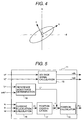
- Controller 1: Controller, 2: AC motor, 3: PWM inverter, 4: Current command generator, 5: Current control section, 6: Three-phase converter, 7: PWM signal generator, 8u, 8v, 8w: Current sensor, 9: Current detector, 10: dq converter, 11: Position estimation means, 12: Speed calculator, 13: Application direction switching means, 15: Voltage signal calculator, 16: Current fluctuation calculator, 20: Reference current fluctuation determination section, 21: Position identifier
- FIG. 1 is a schematic diagram that illustrates a motor control apparatus which is a first embodiment of the present invention.
- a controller 1 inputs torque command Tr* and outputs a signal sent by a PWM signal generator 7 to a PWM inverter 3 so that an AC motor 2 can generate torque specified by the command.
- a current command generator 4 located in the controller 1 inputs torque command Tr* and motor speed ⁇ m ⁇ to determine the current commands iq* and id* so that maximum efficiency can be obtained at the current operating point.
- id* denotes a current command for the direction (d-axis) of the motor rotor's magnetic flux
- iq* denotes a current command for the direction (q-axis) perpendicular to the motor rotor's magnetic flux direction.
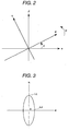
- the above-mentioned d- and q-axis coordinates are rotating coordinate systems as shown in Figure 2.
- the coordinate systems rotate at motor angular speed ⁇ to the coordinate system at rest ⁇ - ⁇ axes (two-phase coordinates converted from U, V, and W phases).
- the phase from the reference ⁇ -axis towards the direction (d-axis) of the motor rotor's magnetic flux be rotor position (magnetic pole position) ⁇ .
- a current control section 5 performs current control calculation on the rotating coordinate d- and q-axes to determine voltage commands Vdc and Vqc on the d- and q-axes.
- the current control of the d- and q-axis coordinates makes it possible to accurately control both the magnetic flux direction current and the current (acting on torque) perpendicular to the magnetic flux direction current, thereby enabling control of the motor torque and magnetic flux.
- a three-phase converter 6 performs coordinate transformation from the d- and q-axes to the U, V, and W phases to obtain three-phase alternating current voltage commands Vu*, Vv*, and Vw*.
- a PWM signal generator 7 converts the alternating current voltage command signals Vu*, Vv*, and Vw* into PWM signals to apply them to the PWM inverter 3.
- a current detector 9 located in the controller 1 imports motor currents iu, iv, and iw detected by three-phase current sensors 8u, 8v, and 8w, and a dq converter 10 calculates currents id ⁇ and iq ⁇ detected on the d- and q-axes and then feeds the result back to the current control section 5.
- the above is the configuration of the motor control system and is also a control method, generally called "vector control”.
- Coordinate transformation formulas used in the three-phase converter 6 and the dq converter 10 are expressed by Equations 1 and 2.
- the former is a calculation formula that converts (three-phase converter 6) d- and q-axis voltages Vd* and Vq* into three-phase voltages Vu*, Vv*, and Vw*
- the latter is a calculation formula that converts (dq converter 10) three-phase currents iu, iv, and iw into d- and q-axis currents iq ⁇ and id ⁇ .
- coordinate transformation requires rotor position ⁇ ( ⁇ C).
- ⁇ C rotor position
- ⁇ C position-sensor
- an induced voltage based method is applied to the motor's high and medium speed range where induced voltage can be detected (estimated).
- a method that utilizes the motor's salient-pole property (Ld ⁇ Lq) is applied to the motor's stop and low speed range where induced voltage is not easily detected.
- Ld denotes the d-axis direction inductance
- Lq denotes the q-axis direction inductance
- reverse salient-pole property The characteristic of the inductance of a reverse salient-pole motor is shown in Figure 3 as an example.
- Figure 3 shows the magnitude of the inductance on the d- and q-axis directions (the distance from the ellipse center 0 to the circumference indicates the magnitude of the inductance).
- the magnetic flux direction inductance Ld becomes minimized and the inductance Lq in the direction perpendicular to the magnetic flux direction becomes maximized.
- a magnetic pole position detection voltage signal is applied (superimposed) to the motor, fluctuation of the generated motor current is detected, and the inductance is measured.
- the direction in which thus measured inductance becomes minimized is the rotor's magnetic flux direction (magnetic pole position).
- I represents the current vector.
- the current vector I causes magnetic saturation, which minimizes the direction's inductance. If a position estimation method based on the above-mentioned salient-pole property is applied when such a characteristic is occurring, the estimated position is not in the d-axis direction, but in the current vector direction. As a result, it may not be possible to accurately estimate the magnetic pole position.
- a magnetic pole position detection (estimate) method is applied in such a situation.
- the basic concept of the method is to detect inductance in the direction where no magnetic saturation has occurred and to detect (estimate) the rotor's position based on the inductance. For example, if current vector I has caused magnetic saturation, which greatly decreases the inductance in that direction, the direction that is least affected by the magnetic saturation is the direction perpendicular to the current vector I (Y direction in Figure 4).
- the inductance of this Y-axis direction (direction perpendicular to the current vector) is the motor inductance that is not affected by magnetic saturation and changes according to the motor's rotor position. Therefore, measuring inductance of the direction perpendicular to the current vector I by using this characteristic makes it possible to estimate the current rotor position.
- a position estimation means 11 detects (estimates) the rotor position.
- the position estimation means 11 outputs the position detection value ⁇ c that is applicable to coordinate transformation calculations in the three-phase converter 6 and the d-q converter 10. Furthermore, motor speed ⁇ m ⁇ can be obtained by calculating the rate of change over time of the position detection value ⁇ c by using a speed calculator 12.
- the position estimation means 11 outputs the position detection value ⁇ c to use it for the coordinate transformation calculations in the three-phase converter 6 and the dq converter 10. Furthermore, motor speed ⁇ m ⁇ can be obtained by calculating the rate of change over time of the position detection value ⁇ c by using a speed calculator 12.
- Figure 5 illustrates an example of configuration of the position estimation means.
- current commands id* and iq* are input to calculate the direction of current vector I.
- current commands id* and iq* are input to calculate the direction of current vector I.
- the voltage signal calculator 15 calculates and determines position estimation voltage signals vdh and vqh that are to be applied to the motor.
- the position estimation voltage signals (vdh, vqh) are for measuring the inductance of the motor, and generally are rectangular wave pulse signals.
- a voltage signal calculator 15 calculates pulse frequency and amplitude as well as an application direction.
- V denotes applied voltage
- ⁇ t denotes current fluctuation measuring time
- a reference inductance determination section 19 inputs torque command Tr* and speed detection value ⁇ m ⁇ to determine reference inductance L*. Then, a position calculator 18 calculates position estimation value ⁇ c based on the deviation between the reference inductance L* and the motor inductance L calculated by the inductance calculator 17.
- the value of inductance L* determined by a reference inductance determination section 19 is the value of the inductance in the direction perpendicular to the current vector I when a position error is zero. If an error occurs in the magnetic pole position estimation value, the detected inductance L becomes different from the reference inductance L*, which makes position estimation possible.
- a rotor position calculator 18 performs proportional and integral operations, for example, to adjust (correct) the position estimation value so that the deviation between the reference inductance L* and the motor inductance L becomes zero. Moreover, the calculation time can be reduced by beforehand measuring the reference inductance L* in each operating point, making the values into a table, and storing them in the memory.
- the above is the configuration example of the position estimation means 11 and its operations.
- a voltage signal calculator 15 in Figure 6 calculates voltage pulse that is to be applied in the pre-determined direction to the motor's current vector I. Furthermore, a current fluctuation calculator 16 calculates current fluctuation ⁇ i which is the same operation as conducted in the Figure 5. As mentioned above, by applying voltage signals in the direction perpendicular to the current vector I, it is possible to measure the inductance of the motor without being affected by magnetic saturation caused by a current. In this configuration example, a method for calculating a position estimation value ⁇ C is different from the method described in said configuration example. This configuration example uses a method that estimates the magnetic pole position by using the current fluctuation condition instead of obtaining inductance.
- a reference current fluctuation determination section 20 inputs torque command Tr* and speed detection value ⁇ m ⁇ to determine reference current fluctuation ⁇ i* according to the current operating point.
- the value of reference current fluctuation ⁇ i* determined by the reference current fluctuation determination section 20 is the value of current fluctuation in the direction perpendicular to current vector I when a position error is zero. If an error occurs in the magnetic pole position estimation value, the detected current fluctuation ⁇ i becomes different from the reference current fluctuation ⁇ i*, which makes position estimation possible.
- the calculation time can be reduced by beforehand measuring reference current fluctuation ⁇ i* in each operating point, making the values into a table, and storing them in the memory.
- the current fluctuation calculator 16 detects current fluctuation ⁇ i generated by application of voltage signals, which is the same operation as conducted by the current fluctuation calculator in Figure 5.
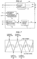
- Figure 7 shows an example of a method for detecting current fluctuation ⁇ i.
- the voltage signal is alternated every period, for example, between the direction (X) of current vector I and the direction (Y) perpendicular to the current vector I.
- the amount of detected current fluctuation includes components of induced voltage and flowing electric current in addition to components of the applied voltage.
- the difference between consecutive current fluctuation amounts e.g. ⁇ i1 and ⁇ i2 is obtained.
- the amount of the current fluctuation caused by application of the voltage can be obtained.
- a position identifier 21 performs feedback control so that detected current fluctuation ⁇ i coincides with reference current fluctuation ⁇ i*. Assuming that the output of this feedback control is position estimation value ⁇ c, the motor's rotor position ⁇ coincides with the position estimation value ⁇ C at the point where ⁇ i* is equal to ⁇ i. That is, it is possible to estimate the rotor position. Similar to the position calculator 18, a position identifier 21 performs control so that the reference current fluctuation ⁇ i* coincides with the current fluctuation ⁇ i by performing proportional and integral operations.
- the motor's rotor position ⁇ coincides with the position estimation value ⁇ C at the point where ⁇ i* is equal to ⁇ i. That is, it is possible to estimate the rotor position.
- the controller 1 determines whether the motor's current operating point is power running or regeneration and then switches the compensation direction.
- the explanation of the embodiment shows that the application direction of the position detection voltage signal is not only the direction perpendicular to the current vector I.
- the reference current fluctuation ⁇ i* changes according to the deviation angle to the direction (i.e. Y-axis direction) perpendicular to current vector I.
- the current fluctuation sensitivity tends to decrease in the directions other than the Y-axis direction regardless of a lead or lag position. Therefore, the accuracy of magnetic pole position detection changes accordingly. That is, because the sensitivity is high in the Y-axis (perpendicular) direction, the accuracy of position detection by feedback control increases. However, as the detection sensitivity decreases, the position detection error increases.
- a broken line in Figure 8 expresses changes in the detection error. The detection error is minimized in the Y-axis direction and increases in other directions regardless of a lead or lag position.
- the present invention applies voltage signals, calculates motor inductance based on the current fluctuation at that moment, and estimates the rotor position. Therefore, for this calculation, it is necessary to obtain accurate voltage signals to be applied for the position detection. Since voltage output by the PWM inverter 3 changes gain according to input voltage of the direct current input voltage (battery Vb), it is necessary to correct the reference current fluctuation ⁇ i according to the fluctuation of direct current voltage, when necessary.
- the position estimation method according to the present invention is not affected by magnetic saturation caused by heavy current. Also, the position estimation method is applicable to the light current area where magnetic saturation has not occurred.
- this method applies position detection voltage signals in the direction 45 degrees from the magnetic flux axis configured in the control system, and estimates the magnetic pole position based on inductance or the current fluctuation condition in that direction. This is because inductance fluctuation is maximized (highest sensitivity) in the direction 45 degrees from the magnetic flux axis, compared to the fluctuation at the rotor position.
- this embodiment inputs three-phase (U, V, W) motor currents iu, iv, and iw.
- two-phase motor current can also be used with this invention.
Applications Claiming Priority (2)
| Application Number | Priority Date | Filing Date | Title |
|---|---|---|---|
| JP2002270968A JP3695436B2 (ja) | 2002-09-18 | 2002-09-18 | 位置センサレスモータ制御方法および装置 |
| JP2002270968 | 2002-09-18 |
Publications (2)
| Publication Number | Publication Date |
|---|---|
| EP1401093A2 true EP1401093A2 (de) | 2004-03-24 |
| EP1401093A3 EP1401093A3 (de) | 2006-01-11 |
Family
ID=31944541
Family Applications (1)
| Application Number | Title | Priority Date | Filing Date |
|---|---|---|---|
| EP03006130A Withdrawn EP1401093A3 (de) | 2002-09-18 | 2003-03-18 | Verfahren zur Motorregelung ohne Positionssensor und Vorrichtung |
Country Status (4)
| Country | Link |
|---|---|
| US (1) | US6788024B2 (de) |
| EP (1) | EP1401093A3 (de) |
| JP (1) | JP3695436B2 (de) |
| KR (1) | KR100747941B1 (de) |
Cited By (7)
| Publication number | Priority date | Publication date | Assignee | Title |
|---|---|---|---|---|
| GB2432734A (en) * | 2005-05-20 | 2007-05-30 | Siemens Ag | Apparatus for the braking of inverter driven induction motors |
| EP1959553A1 (de) * | 2007-02-15 | 2008-08-20 | Sanyo Electric Co., Ltd. | Motorsteuervorrichtung |
| CN101499754B (zh) * | 2008-10-28 | 2011-05-11 | 南京航空航天大学 | 无位置传感器双凸极电机系统及其控制方法 |
| WO2011039273A3 (de) * | 2009-10-01 | 2011-07-07 | Gärtner-Electronic-Design Gmbh | Verfahren und einrichtung zur überwachung und korrektur einer sensorlosen rotorlageerkennung bei permanenterregten motoren |
| US8080956B2 (en) | 2010-08-26 | 2011-12-20 | Ford Global Technologies, Llc | Electric motor torque estimation |
| RU2576246C1 (ru) * | 2012-02-02 | 2016-02-27 | Мицубиси Электрик Корпорейшн | Устройство управления вращающейся машины переменного тока |
| EP3879695A1 (de) * | 2020-03-11 | 2021-09-15 | Mitsubishi Electric R & D Centre Europe B.V. | Verfahren und vorrichtung zur schätzung der position eines rotors eines motors |
Families Citing this family (72)
| Publication number | Priority date | Publication date | Assignee | Title |
|---|---|---|---|---|
| US7180263B2 (en) * | 2000-11-09 | 2007-02-20 | Daikin Industries, Ltd. | Synchronous motor control method and device |
| JP4665360B2 (ja) * | 2001-08-06 | 2011-04-06 | 株式会社安川電機 | 電動機制御装置 |
| JP3661864B2 (ja) * | 2002-03-19 | 2005-06-22 | 日本サーボ株式会社 | ステッピングモータの駆動装置 |
| US6958586B2 (en) * | 2002-07-12 | 2005-10-25 | Mitsubishi Denki Kabushiki Kaisha | Vector control invertor |
| JP4063166B2 (ja) * | 2002-07-31 | 2008-03-19 | 日産自動車株式会社 | 電動機の制御装置 |
| JP3789895B2 (ja) * | 2003-02-28 | 2006-06-28 | 三菱電機株式会社 | 巻線界磁型同期モータの制御装置および巻線界磁型同期モータの回転位置ずれ補正方法 |
| JP2004343833A (ja) * | 2003-05-13 | 2004-12-02 | Toshiba Corp | モータ制御装置 |
| EP1480330A3 (de) * | 2003-05-22 | 2007-09-26 | Jtekt Corporation | Vorrichtung und Verfahren zur steuerung eines Motors |
| JP4241218B2 (ja) * | 2003-06-27 | 2009-03-18 | 株式会社日立産機システム | 交流電動機の制御装置及び交流電動機システム |
| US7276877B2 (en) * | 2003-07-10 | 2007-10-02 | Honeywell International Inc. | Sensorless control method and apparatus for a motor drive system |
| AT500608B1 (de) * | 2004-07-14 | 2008-07-15 | Siemens Ag Oesterreich | Verfahren zur steuerung einer löschvorrichtung für eine rückspeisende stromrichterbrücke |
| US6967454B1 (en) * | 2004-10-20 | 2005-11-22 | Rockwell Automation Technologies, Inc. | Monitoring apparatus and method for monitoring a pole circuit of an electrical power converter |
| JP4592385B2 (ja) * | 2004-10-27 | 2010-12-01 | 株式会社東芝 | 同期機の制御装置 |
| US7211984B2 (en) * | 2004-11-09 | 2007-05-01 | General Motors Corporation | Start-up and restart of interior permanent magnet machines |
| KR100668973B1 (ko) | 2004-11-10 | 2007-01-16 | 삼성전자주식회사 | 모터의 속도/위치 추정방법 |
| KR100665061B1 (ko) * | 2004-12-08 | 2007-01-09 | 삼성전자주식회사 | 모터의 속도 제어장치 및 속도 제어방법 |
| KR100734467B1 (ko) | 2005-02-25 | 2007-07-03 | 윤용호 | 전압펄스 주입방식을 이용한 스위치드 릴럭턴스 모터의 센서리스 제어장치 및 그 방법 |
| US7557530B2 (en) * | 2005-10-12 | 2009-07-07 | Continental Automotive Systems Us, Inc. | Method, apparatus and article for detecting rotor position |
| JP4449882B2 (ja) * | 2005-10-14 | 2010-04-14 | 株式会社デンソー | 車両用発電制御装置 |
| JP2007336641A (ja) * | 2006-06-13 | 2007-12-27 | Denso Corp | 同期モータの位置センサレス駆動装置 |
| JP4928855B2 (ja) * | 2006-07-05 | 2012-05-09 | 株式会社東芝 | 同期機のセンサレス制御装置 |
| JP2008067556A (ja) * | 2006-09-11 | 2008-03-21 | Sanyo Electric Co Ltd | モータ制御装置 |
| DK1914875T3 (da) * | 2006-10-20 | 2019-10-14 | Abb Schweiz Ag | Fremgangsmåde til styring og motorstarteranordning |
| US20090206902A1 (en) * | 2007-01-03 | 2009-08-20 | Yong Li | Method for providing power factor correction including synchronized current sensing and pwm generation |
| JP5107581B2 (ja) * | 2007-01-12 | 2012-12-26 | 三菱電機株式会社 | 電気車の制御装置 |
| US7577545B2 (en) * | 2007-05-29 | 2009-08-18 | Hamilton Sundstrand Corporation | Method and system for estimating rotor angular position and rotor angular velocity at low speeds or standstill |
| US7895003B2 (en) | 2007-10-05 | 2011-02-22 | Emerson Climate Technologies, Inc. | Vibration protection in a variable speed compressor |
| US8950206B2 (en) | 2007-10-05 | 2015-02-10 | Emerson Climate Technologies, Inc. | Compressor assembly having electronics cooling system and method |
| US8539786B2 (en) * | 2007-10-08 | 2013-09-24 | Emerson Climate Technologies, Inc. | System and method for monitoring overheat of a compressor |
| US8448459B2 (en) * | 2007-10-08 | 2013-05-28 | Emerson Climate Technologies, Inc. | System and method for evaluating parameters for a refrigeration system with a variable speed compressor |
| US20090092501A1 (en) * | 2007-10-08 | 2009-04-09 | Emerson Climate Technologies, Inc. | Compressor protection system and method |
| US9541907B2 (en) * | 2007-10-08 | 2017-01-10 | Emerson Climate Technologies, Inc. | System and method for calibrating parameters for a refrigeration system with a variable speed compressor |
| US20090092502A1 (en) * | 2007-10-08 | 2009-04-09 | Emerson Climate Technologies, Inc. | Compressor having a power factor correction system and method |
| US8418483B2 (en) | 2007-10-08 | 2013-04-16 | Emerson Climate Technologies, Inc. | System and method for calculating parameters for a refrigeration system with a variable speed compressor |
| US8459053B2 (en) | 2007-10-08 | 2013-06-11 | Emerson Climate Technologies, Inc. | Variable speed compressor protection system and method |
| JP5130031B2 (ja) * | 2007-12-10 | 2013-01-30 | 株式会社日立製作所 | 永久磁石モータの位置センサレス制御装置 |
| FR2933550B1 (fr) * | 2008-07-01 | 2012-10-12 | Schneider Toshiba Inverter Europe Sas | Procede de determination des inductances d'une machine synchrone a aimants permanents |
| US7911176B2 (en) * | 2008-07-30 | 2011-03-22 | General Electric Company | Systems and methods involving permanent magnet electric machine rotor position determination |
| JP5309838B2 (ja) * | 2008-09-26 | 2013-10-09 | 株式会社安川電機 | 交流電動機の制御装置及びその制御方法 |
| JP4751435B2 (ja) | 2008-10-09 | 2011-08-17 | 株式会社東芝 | モータ磁極位置検出装置,モータ制御装置,モータ駆動システム及び洗濯機 |
| US8253360B2 (en) * | 2009-07-15 | 2012-08-28 | GM Global Technology Operations LLC | Vector controlled motor drive system implementing pulse width modulated (PWM) waveforms |
| US8294413B2 (en) * | 2010-01-05 | 2012-10-23 | GM Global Technology Operations LLC | Induction motor control systems and methods |
| JP5742110B2 (ja) * | 2010-04-14 | 2015-07-01 | 日産自動車株式会社 | 電力変換装置 |
| US8593095B2 (en) | 2011-05-24 | 2013-11-26 | Hamilton Sundstrand Corporation | Wound field synchronous machine rotor tracking using a carrier injection sensorless signal and exciter current |
| JP5408193B2 (ja) * | 2011-06-23 | 2014-02-05 | トヨタ自動車株式会社 | 車両の異常検出装置 |
| US8963459B2 (en) * | 2011-09-07 | 2015-02-24 | Samsung Techwin Co., Ltd. | Method and apparatus for driving alternating-current motor |
| JP5731355B2 (ja) * | 2011-10-27 | 2015-06-10 | 日立オートモティブシステムズ株式会社 | 車両駆動用誘導電動機の制御装置 |
| US8912743B2 (en) * | 2011-11-01 | 2014-12-16 | Simmonds Precision Products, Inc. | Apparatus and method of determining rotor position in a salient-type motor |
| JP5621998B2 (ja) * | 2012-02-22 | 2014-11-12 | 株式会社デンソー | 交流電動機の制御装置 |
| JP5598767B2 (ja) | 2012-02-22 | 2014-10-01 | 株式会社デンソー | 交流電動機の制御装置 |
| JP5488845B2 (ja) | 2012-02-22 | 2014-05-14 | 株式会社デンソー | 交流電動機の制御装置 |
| JP5534252B2 (ja) | 2012-02-22 | 2014-06-25 | 株式会社デンソー | 交流電動機の制御装置 |
| US20150069941A1 (en) * | 2012-04-12 | 2015-03-12 | Hitachi, Ltd. | Three-Phase Synchronous Motor Drive Device |
| US8901869B2 (en) * | 2012-07-31 | 2014-12-02 | Caterpillar Inc. | Hybrid closed loop speed control using open look position for electrical machines controls |
| KR101982281B1 (ko) | 2012-07-31 | 2019-05-27 | 삼성전자주식회사 | 영구자석 동기 전동기에서 생성 가능한 최대 자속을 획득하는 방법 및 장치. |
| KR101397785B1 (ko) * | 2012-12-17 | 2014-05-20 | 삼성전기주식회사 | 모터 구동 장치 및 방법 |
| KR101928437B1 (ko) * | 2013-01-14 | 2018-12-12 | 삼성전자주식회사 | 전동기를 구동하는 인버터의 출력전압을 제어하는 방법 및 장치. |
| JP2014176157A (ja) * | 2013-03-07 | 2014-09-22 | Toshiba Corp | モータ回転位置検出装置,洗濯機及びモータ回転位置検出方法 |
| JP5761243B2 (ja) * | 2013-03-29 | 2015-08-12 | 株式会社安川電機 | モータ制御装置および磁極位置推定方法 |
| JP6401495B2 (ja) | 2014-05-02 | 2018-10-10 | キヤノン株式会社 | モータ制御装置 |
| US10348230B2 (en) * | 2014-09-12 | 2019-07-09 | Mitsubishi Electric Corporation | Control device for AC rotary machine and magnetic-pole-position correction amount calculation method |
| US9705437B2 (en) * | 2014-09-24 | 2017-07-11 | Texas Instruments Incorporated | Angular position estimation for PM motors |
| JP6559058B2 (ja) * | 2015-12-24 | 2019-08-14 | 三星電子株式会社Samsung Electronics Co.,Ltd. | 制御装置、空気調和装置、制御方法 |
| WO2018025319A1 (ja) * | 2016-08-02 | 2018-02-08 | 三菱電機株式会社 | 回転電機の制御装置 |
| US9991827B1 (en) | 2017-02-06 | 2018-06-05 | Texas Instruments Incorporated | Methods and apparatus for automatic lead angle adjustment using fly-back voltage for brushless DC control |
| US11159112B2 (en) | 2018-11-30 | 2021-10-26 | The Trustees Of Columbia University In The City Of New York | Systems and methods for high performance filtering techniques for sensorless direct position and speed estimation |
| CN109802614B (zh) * | 2019-01-01 | 2020-10-30 | 武汉船用电力推进装置研究所(中国船舶重工集团公司第七一二研究所) | 一种永磁同步电机电感参数辨识系统和方法 |
| US10734928B1 (en) | 2019-03-30 | 2020-08-04 | Omron Corporation | Apparatus and method to harvest quadrature encoder signals from generic stepper motor input signals |
| US11206743B2 (en) | 2019-07-25 | 2021-12-21 | Emerson Climate Technolgies, Inc. | Electronics enclosure with heat-transfer element |
| GB201914887D0 (en) | 2019-10-15 | 2019-11-27 | Rolls Royce Plc | Electronic engine controller |
| US11711009B2 (en) | 2019-10-24 | 2023-07-25 | The Trustees Of Columbia University In The City Of New York | Methods, systems, and devices for soft switching of power converters |
| CN110943660B (zh) * | 2019-11-22 | 2021-07-02 | 苏州伟创电气科技股份有限公司 | 同步电机电感检测方法和装置 |
Citations (4)
| Publication number | Priority date | Publication date | Assignee | Title |
|---|---|---|---|---|
| EP1107448A2 (de) * | 1999-12-02 | 2001-06-13 | Hitachi, Ltd. | Motorsteuerungsvorrichtung |
| US6320349B1 (en) * | 1997-02-14 | 2001-11-20 | Satoru Kaneko | Method of estimating field pole position of synchronous motor, motor controller, and electric vehicle |
| US6396229B1 (en) * | 2000-03-06 | 2002-05-28 | Hitachi, Ltd. | Method of estimating a rotor position of synchronous motor, method of controlling synchronous motor with no position sensor and a controller of synchronous motor |
| US20020117990A1 (en) * | 2001-02-27 | 2002-08-29 | Hitachi Ltd. | Motor control apparatus and electric vehicle using same |
Family Cites Families (5)
| Publication number | Priority date | Publication date | Assignee | Title |
|---|---|---|---|---|
| JPH06315291A (ja) * | 1993-04-28 | 1994-11-08 | Hitachi Ltd | 誘導電動機の磁束位置演算法とそれを用いた制御方法 |
| JP3312472B2 (ja) | 1994-03-01 | 2002-08-05 | 富士電機株式会社 | 電動機の磁極位置検出装置 |
| JP3287147B2 (ja) | 1994-11-24 | 2002-05-27 | 株式会社日立製作所 | 誘導電動機の制御方法 |
| US5929400A (en) * | 1997-12-22 | 1999-07-27 | Otis Elevator Company | Self commissioning controller for field-oriented elevator motor/drive system |
| US6489692B1 (en) * | 1999-12-13 | 2002-12-03 | Capstone Turbine Corporation | Method and apparatus for controlling rotation of magnetic rotor |
-
2002
- 2002-09-18 JP JP2002270968A patent/JP3695436B2/ja not_active Expired - Fee Related
-
2003
- 2003-03-18 EP EP03006130A patent/EP1401093A3/de not_active Withdrawn
- 2003-03-18 US US10/390,148 patent/US6788024B2/en not_active Expired - Lifetime
- 2003-03-19 KR KR1020030017045A patent/KR100747941B1/ko not_active IP Right Cessation
Patent Citations (4)
| Publication number | Priority date | Publication date | Assignee | Title |
|---|---|---|---|---|
| US6320349B1 (en) * | 1997-02-14 | 2001-11-20 | Satoru Kaneko | Method of estimating field pole position of synchronous motor, motor controller, and electric vehicle |
| EP1107448A2 (de) * | 1999-12-02 | 2001-06-13 | Hitachi, Ltd. | Motorsteuerungsvorrichtung |
| US6396229B1 (en) * | 2000-03-06 | 2002-05-28 | Hitachi, Ltd. | Method of estimating a rotor position of synchronous motor, method of controlling synchronous motor with no position sensor and a controller of synchronous motor |
| US20020117990A1 (en) * | 2001-02-27 | 2002-08-29 | Hitachi Ltd. | Motor control apparatus and electric vehicle using same |
Cited By (12)
| Publication number | Priority date | Publication date | Assignee | Title |
|---|---|---|---|---|
| GB2432734A (en) * | 2005-05-20 | 2007-05-30 | Siemens Ag | Apparatus for the braking of inverter driven induction motors |
| GB2432734B (en) * | 2005-05-20 | 2007-11-14 | Siemens Ag | Apparatus for the braking of inverter driven induction motors |
| EP1959553A1 (de) * | 2007-02-15 | 2008-08-20 | Sanyo Electric Co., Ltd. | Motorsteuervorrichtung |
| US7482777B2 (en) | 2007-02-15 | 2009-01-27 | Sanyo Electric Co., Ltd. | Motor control device |
| CN101499754B (zh) * | 2008-10-28 | 2011-05-11 | 南京航空航天大学 | 无位置传感器双凸极电机系统及其控制方法 |
| WO2011039273A3 (de) * | 2009-10-01 | 2011-07-07 | Gärtner-Electronic-Design Gmbh | Verfahren und einrichtung zur überwachung und korrektur einer sensorlosen rotorlageerkennung bei permanenterregten motoren |
| US8766579B2 (en) | 2009-10-01 | 2014-07-01 | Gärtner-Electronic-Design Gmbh | Method and device for monitoring and correcting a sensorless rotor position detection in permanently excited motors |
| KR101483217B1 (ko) * | 2009-10-01 | 2015-01-15 | 엘모스 세미콘두크터르 아크티엔게젤샤프트 | 영구적으로 여기되는 모터들에서 무센서 회전자 위치 검출을 모니터링 및 보정하는 방법 및 디바이스 |
| US8080956B2 (en) | 2010-08-26 | 2011-12-20 | Ford Global Technologies, Llc | Electric motor torque estimation |
| RU2576246C1 (ru) * | 2012-02-02 | 2016-02-27 | Мицубиси Электрик Корпорейшн | Устройство управления вращающейся машины переменного тока |
| EP3879695A1 (de) * | 2020-03-11 | 2021-09-15 | Mitsubishi Electric R & D Centre Europe B.V. | Verfahren und vorrichtung zur schätzung der position eines rotors eines motors |
| WO2021181806A1 (en) * | 2020-03-11 | 2021-09-16 | Mitsubishi Electric Corporation | Method and device for determining a position of a rotor of a three-phase motor |
Also Published As
| Publication number | Publication date |
|---|---|
| JP3695436B2 (ja) | 2005-09-14 |
| US20040051495A1 (en) | 2004-03-18 |
| KR20040025530A (ko) | 2004-03-24 |
| US6788024B2 (en) | 2004-09-07 |
| EP1401093A3 (de) | 2006-01-11 |
| JP2004112898A (ja) | 2004-04-08 |
| KR100747941B1 (ko) | 2007-08-08 |
Similar Documents
| Publication | Publication Date | Title |
|---|---|---|
| US6788024B2 (en) | Position-sensorless motor control method and apparatus | |
| US7928675B2 (en) | Feedback control method and apparatus for electric motor | |
| EP2472716B1 (de) | Störungserkennungsvorrichtung für einen synchronen permanentmagnetelektromotor | |
| US7023170B2 (en) | Origin offset calculation method of rotational position detecting device of electric motor and motor control device using the calculation method | |
| EP1378990B1 (de) | Steuergerät für einen Elektromotor | |
| EP1748550B1 (de) | Synchron-maschinensteuerung | |
| EP2424105B1 (de) | Vektorsteuerungsvorrichtung und Motorsteuerungssystem | |
| EP2827493B1 (de) | Vorrichtung zum steuern eines elektromotors und verfahren zum steuern eines elektromotors | |
| US20030020429A1 (en) | Motor controller | |
| US20010028236A1 (en) | Speed control apparatus for synchronous reluctance motor | |
| US20020117990A1 (en) | Motor control apparatus and electric vehicle using same | |
| US6194865B1 (en) | Control method and system for electric rotary machine | |
| US10263559B2 (en) | Synchronous machine controller | |
| US20080180054A1 (en) | Control apparatus for ac rotary machine and method for measuring electrical constant of ac rotary machine using the control apparatus | |
| US9590551B2 (en) | Control apparatus for AC motor | |
| JP2000050689A (ja) | 交流電動機の駆動制御装置 | |
| US9419555B2 (en) | Synchronous machine control apparatus | |
| US20140225540A1 (en) | Control apparatus for ac motor | |
| US10594240B2 (en) | Control device for alternating current motor | |
| EP1681762B1 (de) | Synchronmotorantriebssystem und Verfahren | |
| WO2011070651A1 (ja) | 電力変換装置 | |
| US20010028229A1 (en) | Speed electromotive force phase control system adapted to low speed | |
| KR100563225B1 (ko) | 유도전동기의제어장치 | |
| US20230336098A1 (en) | Motor control device and motor control method | |
| JP4023280B2 (ja) | モータ制御装置 |
Legal Events
| Date | Code | Title | Description |
|---|---|---|---|
| PUAI | Public reference made under article 153(3) epc to a published international application that has entered the european phase |
Free format text: ORIGINAL CODE: 0009012 |
|
| AK | Designated contracting states |
Kind code of ref document: A2 Designated state(s): AT BE BG CH CY CZ DE DK EE ES FI FR GB GR HU IE IT LI LU MC NL PT SE SI SK TR |
|
| AX | Request for extension of the european patent |
Extension state: AL LT LV MK RO |
|
| PUAL | Search report despatched |
Free format text: ORIGINAL CODE: 0009013 |
|
| AK | Designated contracting states |
Kind code of ref document: A3 Designated state(s): AT BE BG CH CY CZ DE DK EE ES FI FR GB GR HU IE IT LI LU MC NL PT SE SI SK TR |
|
| AX | Request for extension of the european patent |
Extension state: AL LT LV MK RO |
|
| 17P | Request for examination filed |
Effective date: 20060609 |
|
| AKX | Designation fees paid |
Designated state(s): DE FR GB IT |
|
| STAA | Information on the status of an ep patent application or granted ep patent |
Free format text: STATUS: THE APPLICATION HAS BEEN WITHDRAWN |
|
| 18W | Application withdrawn |
Effective date: 20090402 |