EP1398225A2 - Kfz-Sicherheitseinrichtung, insbesondere Trennnetz - Google Patents
Kfz-Sicherheitseinrichtung, insbesondere Trennnetz Download PDFInfo
- Publication number
- EP1398225A2 EP1398225A2 EP03019111A EP03019111A EP1398225A2 EP 1398225 A2 EP1398225 A2 EP 1398225A2 EP 03019111 A EP03019111 A EP 03019111A EP 03019111 A EP03019111 A EP 03019111A EP 1398225 A2 EP1398225 A2 EP 1398225A2
- Authority
- EP
- European Patent Office
- Prior art keywords
- motor vehicle
- deformation body
- safety device
- vehicle safety
- carrier
- Prior art date
- Legal status (The legal status is an assumption and is not a legal conclusion. Google has not performed a legal analysis and makes no representation as to the accuracy of the status listed.)
- Granted
Links
Images


Classifications
-
- F—MECHANICAL ENGINEERING; LIGHTING; HEATING; WEAPONS; BLASTING
- F16—ENGINEERING ELEMENTS AND UNITS; GENERAL MEASURES FOR PRODUCING AND MAINTAINING EFFECTIVE FUNCTIONING OF MACHINES OR INSTALLATIONS; THERMAL INSULATION IN GENERAL
- F16F—SPRINGS; SHOCK-ABSORBERS; MEANS FOR DAMPING VIBRATION
- F16F7/00—Vibration-dampers; Shock-absorbers
- F16F7/12—Vibration-dampers; Shock-absorbers using plastic deformation of members
- F16F7/125—Units with a telescopic-like action as one member moves into, or out of a second member
-
- B—PERFORMING OPERATIONS; TRANSPORTING
- B60—VEHICLES IN GENERAL
- B60R—VEHICLES, VEHICLE FITTINGS, OR VEHICLE PARTS, NOT OTHERWISE PROVIDED FOR
- B60R21/00—Arrangements or fittings on vehicles for protecting or preventing injuries to occupants or pedestrians in case of accidents or other traffic risks
- B60R21/02—Occupant safety arrangements or fittings, e.g. crash pads
- B60R21/06—Safety nets, transparent sheets, curtains, or the like, e.g. between occupants and glass
-
- B—PERFORMING OPERATIONS; TRANSPORTING
- B60—VEHICLES IN GENERAL
- B60R—VEHICLES, VEHICLE FITTINGS, OR VEHICLE PARTS, NOT OTHERWISE PROVIDED FOR
- B60R21/00—Arrangements or fittings on vehicles for protecting or preventing injuries to occupants or pedestrians in case of accidents or other traffic risks
- B60R21/02—Occupant safety arrangements or fittings, e.g. crash pads
- B60R21/06—Safety nets, transparent sheets, curtains, or the like, e.g. between occupants and glass
- B60R2021/065—Safety nets, transparent sheets, curtains, or the like, e.g. between occupants and glass comprising energy absorbing mounting means
Definitions
- the invention relates to a motor vehicle safety device, in particular a motor vehicle separation network, according to the preamble of Claim 1.
- Known automotive separation networks usually have a lower and an upper handrail, between which there is a net-like Material web is located.
- the separation network can be between one retracted rest position, in which the network on a with a Resetting force in the retraction direction of the spring-loaded winding shaft inside a housing is kept compressed, and one extended working position. In the working position closes the net in a motor vehicle between the top of the Vehicle rear backrest and the headlining opening.
- the invention relates not only to motor vehicle separation networks, but can also be used, for example, in vehicle load compartment covers etc. find.
- the known automotive separation networks are used in the case of strong ones Accelerations of the vehicle, such as in the case of a Crashes occur to prevent the in a cargo hold of the vehicle objects thrown into the passenger compartment become.
- the upper handrail is in the prior art in Vehicle-side fastenings hooked in.
- the Handrail fasteners provided, for example expanding mushroom-like end pieces for attachment in Provide mounting grooves on the vehicle.
- DE 40 10 209 A1 proposes energy-consuming Means on the handrail of a separation network by constricting the provide tubular body, with a tapered after inside extending end piece is provided, which the Bead-like impressions of the tube deformed in the event of a crash.
- Manufacturing and assembly tolerances are problematic here Bead embossing, since the exact deformation forces and their Forwarding depends directly on the tolerances.
- the holding tube of the tie rod that is the tubular body itself is deformed because of the danger an overuse of the pipe, possibly one Breaking the pipe in the event of a crash by weakening the pipe, namely by reducing the buckling stiffness.
- the invention is based on the last described State of the art, the well-known vehicle security device to develop in such a way that with improved energy consumption a simplified construction is possible.
- the invention solves this problem with the features of Claim 1, and is accordingly characterized in that the Carrier has a thickened end with one opposite a first Cross-sectional area of the axial section greatly enlarged second Cross-sectional area shows that the constriction in the event of a crash indirectly or directly an abutment for the deformation body provides, and that the thickened end thrust surfaces for a thrust deformation of the deformation body.
- An essential feature of the invention is that Providing a thickened end of the beam on the push surfaces provided for a shear deformation of the deformation body are.
- the thickened end has a cross-sectional area that compared to the cross-sectional area of the axial section clearly is enlarged so that, for example, a substantially T-shaped Extension of the axial section towards the thickened end results. Because of this extension with accompanying Shear areas can significantly increase the cross-sectional area are provided which the deformation body in some way can compress axially, and in this way for a thrust deformation to care.
- the deformation process can be seen imagine in such a way that due to the large, acting forces the Deformation body behaves like a very viscous liquid and flows into the provided alternative rooms.
- the kinetic energy of the carrier is so high that the Deformation body is completely deformed - flow Material areas of the deformation body along different Directions.
- alternative spaces of the type of Attenuation zones in the form of axial grooves on Deformation body can be provided in the material areas of the Deformation body are pressed in during the Deformation body is axially compressed.
- the deformation body changes its shape geometric structure completely and not only flows on the thickened End of the carrier over, but also squeezes through the Area of the tubular body near the constriction, that is not constricted.
- the deformations are due to the Arrangement of large push surfaces in connection with the Arrangement of alternative rooms, zones of weakness and / or Ribs on the deformation body are easily predictable.
- the Deformed body deformed at the same time as a whole achieved that high proportion of kinetic energy in deformation energy is converted and absorbed in this way.
- the deformation body can be any in the axial respect be long and in this way also very large kinetic Absorb energies.
- the solution according to the invention also provides that the deformation body is fixed to an axial section of the carrier is arranged.
- the Deformation body is attached directly to the axial section.
- the deformation body is provided in a particularly advantageous manner the deformation body as extrusion coating of the axial section train.
- Deformation body in several parts, consisting of several components, form and this by reaching around the axial section For example, to clip to fasten together.
- the principle of the invention is also that the Deformation body not necessarily on a separate Component must support, but on the one Bead embossment of the tubular body formed constriction can support. In this way, the number of items be reduced, which is a cheaper manufacture and one allows easier assembly.
- the configuration of the deformation body according to the invention such that it can be deformed by a shear deformation namely that the body can flow away easily and that abutments provided by the bead-like embossing basically withstands the forces of deformation. It is advantageous the constriction chosen such that in the area of Constriction free spaces between the outer surface of the Carrier and the inner surface of the tube exist with others Words the constriction still provides certain alternative spaces. These additional escape areas also make part of the Flow through the deformation body in the event of a crash.
- the cross section of the beam widens from the axial section substantially T-shaped to the thickened end.
- the thrust surfaces are preferably in contact the two side legs of the crossbar of the big T, what a particularly good power distribution ensures.
- the proposed cross-sectional shapes also one Anti-rotation of the carrier within the tubular body reached.
- a deformation of the deformation body in the event of a crash take place essentially over its entire axial length.
- an optimal force distribution in Crash trap reached because the thrust surfaces over the acting forces distribute the entire volume of the deformation body.
- the invention is not only in the area of the conical extension of the end thickened a deformation of the deformation body radially reached outward, the radial projections on the inner wall and digging along the deformation body, but it is in the Crash case a substantial part of the total volume of the Deformation body pushed in front of the push surfaces and thereby deformed several times.
- the deformation body from an overmolding of the Axial section formed. This way one becomes special simple construction of the holder and the deformation body achieved, because these are pre-assembled, combined into one unit, in which tubular body can be used for assembly.
- embossing abutment surfaces on the carrier are left.
- the provision of embossing abutment surfaces offers the Advantage that the arrangement of the constriction by attaching a Beading in the tubular body in a particularly simple manner can be carried out, the support preferably consisting of steel provides suitable abutment surfaces for this stamping process.
- the embossing abutment surfaces are directly from one Formed outside of the carrier so that this is not from a Plastic encapsulation are covered with and during the Attaching the bead damage to the deformation body is completely excluded.
- the deformation body consists of at least two components.
- this embodiment which in particular provides that two cup-shaped components are provided, which are attached to each other by clips can be fastened and encompass the axial section in this way, there is the advantage that the deformation body is particularly is manufactured in a simple manner and can be fastened to the axial section.
- the deformation body has at least one rib, which is in particular essentially over the entire length of the Axial section extends.
- the provision of at least one axial Rib on the deformation body ensures a very accurate definable to deformable volume of the deformation body in the Crash. Attaching a rib also ensures that too at least a second alternative space for material areas of the Information body are provided in the event of a crash. The next to the Axial rib inevitably provide the lateral clearances provided Alternative spaces through the formation of weakening zones Available in the material areas of the rib for deformation and axial compression of the deformation body can flow into it.
- a second escape room by arranging at least one axially extending groove provided on the deformation body.
- the connection of such grooves is very precise in size defined alternative spaces available in the event of a deformation of the Deformation body the displaced material areas of the Can absorb deformation body.
- the Invention corresponds to the cross-sectional area of the thickened end at least 1.3 times the cross-sectional area of the Axial section. From this ratio of cross-sectional area, for example of the thickened end to the cross-sectional area of the axial section sufficiently large push surfaces are provided, which are suitable for a Shear deformation of the deformation body can provide. at an optimal embodiment of the invention corresponds to Cross-sectional area of the thickened end approximately twice that Cross-sectional area of the axial section.
- FIG. 1 shows a canceled tubular body 12 which forms the tie rod 11. Is shown only the related to the vehicle, laterally outer area, so that one Viewer of Figures 1 to 3 and 6, the handrail with respect to Figures to the left must imagine. Is shown only that area of the holding rod 11 that has a holder 13 axially displaceable along the double arrow y (that is, transverse to Direction x of the vehicle).
- the tube 12 is not shown
- the holder 13 is in the essentially axially elongated and extends approximately from the inner end denoted by reference numeral 17 to to a mushroom-like widened end 14.
- the mushroom-like end 14 is used, for example, for inclusion in not shown vehicle-side receiving grooves that are undercut and in Area of the C-pillar or the headlining of the vehicle can.
- the design of the fastener 14 is freely selectable with regard to its geometry.
- the holder 13 is axial within the tube 12 Slidable over a certain area, spring-loaded, added. To release the holder 13 from the tube 12 prevent, is first on a bead-like embossing 16th pointed out, which is made directly on the tube 12, after the holder - enough deep - into the interior of the tube 12 has been introduced.
- the inner, thickened end 17 of the Carrier 15 for the fastener 14 is inward Constriction 16 arranged so that the constriction 16 a would ensure positive locking.
- the carrier 15 is integral and integral connected to the fastener 14, however not necessarily the case.
- the carrier 15 consists of a one-piece solid component Steel.
- the carrier 15 has a first thickening 17 (inner, thickened end 17) and an outer thickening 18 (outer end 18), with the bead-like constriction 16 between the two Ends 17, 18 lies.
- the axial displaceability of the carrier 15 within the tube 12 is cranked for inward movement Area 35 limited, so by striking the cranked Area 35 on the mouth side of the tube 12. Likewise the inward movement of the carrier 15 is also caused by the striking of the outer end 18 with the constriction 16 limited.
- On Extending the carrier 15 for the holder 13 is normal Loads, i.e. not in the event of a crash, by striking one conical section 33 of a deformation body 29 to the bead-like constriction 16 limited.
- a spring element 19 is between the inner end 17 of the Carrier 15 and a support 20 for the spring element 19th positioned.
- the support 20 is, for example, a split pin arranged and attached directly to the tube 12.
- the beam 15 made of steel is overmolded surrounded by plastic, which has a first section 21, the forms the deformation body 29 and an axial section 27 of the Straps around 15.
- the extrusion coating 21 also extends along a second overmolding section 22, which, however, a has a smaller radial diameter and is not part of the Deformation body 29 is. After an interruption it closes 3, in addition, a third section 23 of a Overmoulding, which is finally in a sleeve-like casing 24 of the outer end 18 of the carrier 15 opens.
- the encapsulation is, for example, made of polyamide, if necessary short fiber reinforced, made of GRP-reinforced plastic or one Formed elastomer.
- the carrier 15 is within its entire axial, within of the interior of the tube 12 according to FIG. 3 arranged length overmoulded, only embossing abutment surfaces 25 being left.
- the embossing abutment surfaces 25 are opposite one another arranged and serve a particularly simple attachment of the Beading 16.
- the holder 15 only has to be so far into the tube 12 that the abutment surfaces 25 axially there be positioned where the constriction 16 should be generated.
- Special aids must be used with the Deformation process can not be made, the made of steel beam 15 a sufficient abutment for the Deformation forces when generating the bead 16 provides and the Manufacturing tolerances are thus easy to handle.
- the carrier 15 is in the area of the embossing abutment surfaces 25 moreover, as can be seen in FIG. 3, slightly thicker trained as in its neighboring areas by the Injection molding 21, 22 and 23 are surrounded. In this way the Outside of the beam over a very large axial section trained to be flush overall.
- FIG. 4 Between the outer surface of the deformation body 29 and the inner circumferential surface of the tube 12 is shown in FIG. 4 a further radial escape space 32a.
- FIG. 5 shows a cross section through the inner thickened end 17 of the carrier 15.
- the Cross-sectional area 28 of the hidden end 17 is significantly larger than the cross-sectional area 26 of the carrier 15 in the region of the Axial section 27. Contrary to the prior art takes place in this way an actual cross-sectional expansion takes place, and not just an enlargement of the envelope of the axial section relative to the thickened end.
- the formation of the deformation body 29 as an overmolding 21 the carrier 15 is not only inexpensive, but also allows particularly good tolerances, especially since the deformation body 29 can be designed in such a way that in connection with the sizes of the Thrust surfaces 34 provided for precisely predeterminable conditions without being subject to mandatory tolerances during installation of the holder 13, in the attachment of the constriction 16 or in the Assembly of the pipe arrives.
- the arrangement of Deformation body 29 and holder 15 such that the Deformation body 29 is attached directly in the holder 15, provides for a particularly good handling of the tolerances, because the decisive area ratios that are necessary for controllability of the Deformation process are important, are very precisely predetermined and no later installation, and assembly tolerances are subject.
- the deformation body 29 for the essentially unchanged Carrier 15 formed as a two-part component is the deformation body 29 for the essentially unchanged Carrier 15 formed as a two-part component.
- the Deformation body 29 ' consists of two half-shells according to FIG. 7, which are manufactured as separate plastic injection molded parts and z. B. can be attached to each other by clips. The clips fasteners are not shown.
- the dividing line between the Both shells can, for example, along the parting lines a or a '.
- the axial section 27 essentially has one here rectangular cross-sectional area 26, which the area of inner thickened end 17 into a substantially circular Cross-sectional area 28 expanded.
- the push surfaces 34 enlarge the Cross-sectional area 28 in this way again clearly opposite the cross-sectional area 26.
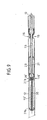
- Fig. 9 shows schematically a third embodiment of the Arrangement of a deformation body 29 according to the invention within a tube 12 of a support rod 11 of a separation network 10.
- the third embodiment corresponds almost identical to that 3, wherein the arrangement of the Spring element 19 'in the embodiment of FIG. 9 slightly was changed.
- the carrier 15 of the holder 13 slightly inward, that is to say to the left with respect to FIG and leads to a shaft 36.
- the spring element 19 ' is between two Washers 37a and 37b are arranged, both of the shaft 36 be penetrated.
- An additional constriction 16 ' which is also has been made as a corrugation, but clearly shallower than the bead embossing 16 ensures a loose hold of the ring body 37b.
- the second washer 37a is loose slidable within the tube 12.
- the spring 19 ' acts as a compression spring and ensures that the holder 13 constantly inside is biased.
- the spring element 19 ' is thus supported with its right end in the washer 37b as an abutment.
- the spring element is 19th also designed as a compression spring and ensures that the Carrier 15 and also the fastener 14 to the outside is biased.
- biasing direction i.e. a bias towards the outside or inside
- a compression spring of course, optionally exchanged by a tension spring become.
Landscapes
- Engineering & Computer Science (AREA)
- General Engineering & Computer Science (AREA)
- Mechanical Engineering (AREA)
- Vibration Dampers (AREA)
- Automotive Seat Belt Assembly (AREA)
Abstract
Description
Claims (17)
- Kfz-Sicherheitseinrichtung (10), insbesondere Trennnetz, mit einem Auszugselement (11), wie Zugstange, Endboard od. dgl., welches zumindest einen Abschnitt eines rohrförmigen, mit wenigstens einer Einschnürung (16) versehenen Körpers (12) aufweist, in dem axial verschieblich ein Träger (15) für ein Befestigungselement (14) zur fahrzeugseitigen Anbringung angeordnet ist, wobei ein Deformationskörper (29, 29') zur Aufnahme kinetischer Energie im Falle höchster Belastungen (Crashfall) fest an einem Axialabschnitt (27) des Trägers (15) angeordnet und mit diesem bewegungseinheitlich gekoppelt ist, dadurch gekennzeichnet, dass der Träger (15) ein verdicktes Ende (17) mit einer gegenüber einer ersten Querschnittsfläche (26) des Axialabschnittes stark vergrößerten zweiten Querschnittsfläche (28) aufweist, dass im Crashfall die Einschnürung (16) mittelbar oder unmittelbar ein Widerlager für den Deformationskörper (29, 29') bereitstellt, und dass das verdickte Ende (17) Schubflächen (34) für eine Schub-Deformation des Deformationskörpers (29, 29') aufweist.
- Kfz-Sicherheitseinrichtung nach Anspruch 1, dadurch gekennzeichnet, dass der Axialabschnitt (27) mit dem verdickten Ende (17) einstückig-stoffschlüssig verbunden ist.
- Kfz-Sicherheitseinrichtung nach Anspruch 1 oder 2, dadurch gekennzeichnet, dass sich der Querschnitt des Trägers (15) von dem Axialabschnitt (27) hin zu dem verdickten Ende (17) im wesentlichen T-förmig erweitert.
- Kfz-Sicherheitseinrichtung nach einem der Ansprüche 1 bis 3, dadurch gekennzeichnet, dass im Crashfall eine Verformung des Deformationskörpers (29, 29') im wesentlichen über seine gesamte axiale Länge (I) stattfindet.
- Kfz-Sicherheitseinrichtung nach einem der Ansprüche 1 bis 4, dadurch gekennzeichnet, dass die Schubflächen (34) im Crashfall den Deformationskörper wenigstens partiell axial stauchen.
- Kfz-Sicherheitseinrichtung nach einem der Ansprüche 1 bis 5, dadurch gekennzeichnet, dass der Deformationskörper von einer Umspritzung (21) des Axialabschnittes gebildet ist.
- Kfz-Sicherheitseinrichtung nach einem der Ansprüche 1 bis 5, dadurch gekennzeichnet, dass der Deformationskörper (29') aus wenigstens zwei Bauteilen (29a, 29b) besteht.
- Kfz-Sicherheitseinrichtung nach Anspruch 7, dadurch gekennzeichnet, dass die Bauteile (29a, 29b) im wesentlichen schalenförmig ausgebildet sind und unter Umgreifung des Axialabschnittes (27) unmittelbar aneinander befestigbar sind.
- Kfz-Sicherheitseinrichtung nach Anspruch 7 oder 8, dadurch gekennzeichnet, dass die Bauteile aneinander clipsbar sind.
- Kfz-Sicherheitseinrichtung nach einem der vorangegangenen Ansprüche, dadurch gekennzeichnet, dass an dem Träger (15) Präge-Widerlagerflächen (25) belassen sind.
- Kfz-Sicherheitseinrichtung nach einem der vorangegangenen Ansprüche, dadurch gekennzeichnet, dass der Träger (15) aus Metall, insbesondere aus Stahl, und der Deformationskörper (29, 29') aus Kunststoff besteht.
- Kfz-Sicherheitseinrichtung nach einem der vorangegangenen Ansprüche, dadurch gekennzeichnet, dass dem Deformationskörper wenigstens ein Ausweichraum (32a, 32b) zugeordnet ist.
- Kfz-Sicherheitseinrichtung nach Anspruch 12, dadurch gekennzeichnet, dass ein erster Ausweichraum (32a) zwischen der Außenmantelfläche des Deformationskörpers (29, 29') und der Innenmantelfläche des rohrförmigen Körpers (12) angeordnet ist.
- Kfz-Sicherheitseinrichtung nach einem der vorangegangenen Ansprüche, dadurch gekennzeichnet, dass der Deformationskörper wenigstens eine Rippe (31) aufweist, die sich insbesondere im wesentlichen über die gesamte Länge (I) des Axialabschnitts (27) erstreckt.
- Kfz-Sicherheitseinrichtung nach einem der vorangegangenen Ansprüche, dadurch gekennzeichnet, dass wenigstens ein zweiter Ausweichraum (32b), insbesondere nach Art einer Schwächungszone, durch Anordnung von zumindest einer axial verlaufenden Nut (30) an dem Deformationskörper (29, 29') vorgesehen ist.
- Kfz-Sicherheitseinrichtung nach einem der vorangegangenen Ansprüche, dadurch gekennzeichnet, dass die Querschnittsfläche (28) des verdickten Endes (17) wenigstens dem 1,3-fachen der Querschnittsfläche (26) des Axialabschnittes (27) entspricht.
- Kfz-Sicherheitseinrichtung nach einem der vorangegangenen Ansprüche, dadurch gekennzeichnet, dass die Querschnittsfläche (28) des verdickten Endes (17) ungefähr dem 2-fachen der Querschnittsfläche (26) des Axialabschnittes (27) entspricht.
Applications Claiming Priority (2)
| Application Number | Priority Date | Filing Date | Title |
|---|---|---|---|
| DE10242510 | 2002-09-12 | ||
| DE10242510A DE10242510B4 (de) | 2002-09-12 | 2002-09-12 | Kfz-Sicherheitseinrichtung, insbesondere Trennnetz |
Publications (3)
| Publication Number | Publication Date |
|---|---|
| EP1398225A2 true EP1398225A2 (de) | 2004-03-17 |
| EP1398225A3 EP1398225A3 (de) | 2004-07-28 |
| EP1398225B1 EP1398225B1 (de) | 2006-11-15 |
Family
ID=31724725
Family Applications (1)
| Application Number | Title | Priority Date | Filing Date |
|---|---|---|---|
| EP03019111A Expired - Lifetime EP1398225B1 (de) | 2002-09-12 | 2003-08-23 | Kfz-Sicherheitseinrichtung, insbesondere Trennnetz |
Country Status (3)
| Country | Link |
|---|---|
| US (1) | US6871894B2 (de) |
| EP (1) | EP1398225B1 (de) |
| DE (2) | DE10242510B4 (de) |
Families Citing this family (17)
| Publication number | Priority date | Publication date | Assignee | Title |
|---|---|---|---|---|
| DE10242510B4 (de) * | 2002-09-12 | 2005-12-08 | Bos Gmbh & Co. Kg | Kfz-Sicherheitseinrichtung, insbesondere Trennnetz |
| JP4204037B2 (ja) * | 2003-02-21 | 2009-01-07 | 芦森工業株式会社 | 荷崩れ防止装置 |
| US6962382B2 (en) * | 2003-05-23 | 2005-11-08 | David Scarlett | Barrier system |
| DE102004008874A1 (de) * | 2004-02-18 | 2005-09-08 | Bos Gmbh & Co. Kg | Funktionseinheit für einen Fahrzeuginnenraum |
| US7066516B2 (en) * | 2004-03-31 | 2006-06-27 | Lear Corporation | Rear vehicle storage system |
| JP4310700B2 (ja) * | 2004-09-30 | 2009-08-12 | ブラザー工業株式会社 | プロセスカートリッジおよび画像形成装置 |
| US20070296258A1 (en) * | 2006-06-23 | 2007-12-27 | Kyle Calvert | Rear seat extended fold and kneel reconfiguration |
| DE102007060974A1 (de) | 2006-12-15 | 2008-07-10 | Ymos Gmbh | Stange für Gepäcknetze |
| US20090033114A1 (en) * | 2007-08-02 | 2009-02-05 | Thomas Steigerwald | Loading area cover for a motor vehicle |
| JP5189006B2 (ja) * | 2009-02-13 | 2013-04-24 | 芦森工業株式会社 | カーゴネット装置 |
| JP5129175B2 (ja) * | 2009-02-13 | 2013-01-23 | 芦森工業株式会社 | カーゴネット装置 |
| US8272674B2 (en) | 2010-09-22 | 2012-09-25 | Techcognic Llc | Seat partition and method for partitioning passengers in a vehicle |
| JP5044745B2 (ja) * | 2011-02-14 | 2012-10-10 | 株式会社トヨックス | 陳列什器及び陳列スタンド |
| DE102013010884C5 (de) * | 2013-07-01 | 2025-07-03 | Macauto Industrial Co., Ltd. | Sicherheitsnetz für ein Fahrzeug |
| DE102013108954A1 (de) * | 2013-08-20 | 2015-03-12 | Dr. Ing. H.C. F. Porsche Aktiengesellschaft | Befestigungsvorrichtung für ein Schutz- bzw. Trennnetz in einem Kraftfahrzeug |
| US20150328965A1 (en) * | 2014-05-15 | 2015-11-19 | Macauto Industrial Co., Ltd. | Extension assembly for a sidebar of a sunshade |
| RU193089U1 (ru) * | 2019-07-05 | 2019-10-14 | Павел Алексеевич Беккер | Сиденье автомобиля, оборудованное устройством для предотвращения падения груза |
Family Cites Families (21)
| Publication number | Priority date | Publication date | Assignee | Title |
|---|---|---|---|---|
| US4222601A (en) * | 1978-10-16 | 1980-09-16 | Irvin Industries Inc. | Automobile compartment cover |
| US4971378A (en) * | 1989-11-29 | 1990-11-20 | Setina John R | Pivoted automobile partition with adjustable spring bias |
| DE4010209C2 (de) * | 1990-03-30 | 1994-03-10 | Baumeister & Ostler Gmbh Co | Sicherheitsnetz |
| US5427466A (en) * | 1993-09-09 | 1995-06-27 | Williams Controls, Inc. | Coupling for remote control of an engine |
| DE4336380C2 (de) * | 1993-10-25 | 1995-08-10 | Baumeister & Ostler Gmbh Co | Sicherheitsnetzanordnung |
| US5437324A (en) * | 1994-01-19 | 1995-08-01 | Newell Operating Company | Shade with variable load braking and lift assist |
| DE4441610C2 (de) * | 1994-11-23 | 1997-10-02 | Baumeister & Ostler Gmbh Co | Sicherheitsnetzanordnung |
| US6817644B2 (en) * | 1995-11-22 | 2004-11-16 | Exco Automotive Solutions, L.P. | Load retaining barrier net for motor vehicle |
| US5697663A (en) * | 1995-12-27 | 1997-12-16 | Chenowth; Lynn | Heap climbing container cover system |
| US5711568A (en) * | 1996-02-05 | 1998-01-27 | Diem; D.W. | Retractable cargo cover |
| DE59709928D1 (de) * | 1996-12-06 | 2003-05-28 | Bos Gmbh | Sicherheitsnetzanordnung mit vereinfachter bedienung |
| DE19728587C1 (de) * | 1997-07-04 | 1998-11-05 | Baumeister & Ostler Gmbh Co | Sicherheitsnetzanordnung mit Belastungsanzeige |
| DE19735463C1 (de) * | 1997-08-16 | 1999-03-04 | Baumeister & Ostler Gmbh Co | Sicherheitsnetz mit erhöhter Festigkeit der Wickelwelle |
| DE19736170C1 (de) * | 1997-08-20 | 1999-04-29 | Baumeister & Ostler Gmbh Co | Abdeckrollo mit Hebelmechanik |
| US5975599A (en) * | 1997-09-30 | 1999-11-02 | Goldstein; Allan J. | Vehicle body protection device and method |
| DE19927384C1 (de) * | 1999-06-16 | 2000-12-07 | Bos Gmbh | Trenneinrichtung mit variabler Rückzugskraft |
| DE19930136C5 (de) * | 1999-07-01 | 2004-11-18 | Bos Gmbh & Co. Kg | Laderaumabtrennung |
| DE19940602A1 (de) * | 1999-08-27 | 2001-04-05 | Baumeister & Ostler Gmbh Co | Laderaumabdeckung für ein Kraftfahrzeug |
| DE19944003C1 (de) * | 1999-09-14 | 2001-03-22 | Baumeister & Ostler Gmbh Co | Faltbare Trenneinrichtung |
| DE10044958C2 (de) * | 2000-09-12 | 2003-04-10 | Bos Gmbh | Schutzvorrichtung zur Sicherung eines Laderaumes in einem Fahrzeuginnenraum |
| DE10242510B4 (de) * | 2002-09-12 | 2005-12-08 | Bos Gmbh & Co. Kg | Kfz-Sicherheitseinrichtung, insbesondere Trennnetz |
-
2002
- 2002-09-12 DE DE10242510A patent/DE10242510B4/de not_active Withdrawn - After Issue
-
2003
- 2003-08-23 DE DE50305667T patent/DE50305667D1/de not_active Expired - Lifetime
- 2003-08-23 EP EP03019111A patent/EP1398225B1/de not_active Expired - Lifetime
- 2003-09-12 US US10/661,359 patent/US6871894B2/en not_active Expired - Fee Related
Also Published As
| Publication number | Publication date |
|---|---|
| DE10242510B4 (de) | 2005-12-08 |
| DE10242510A1 (de) | 2004-04-15 |
| DE50305667D1 (de) | 2006-12-28 |
| US6871894B2 (en) | 2005-03-29 |
| EP1398225B1 (de) | 2006-11-15 |
| EP1398225A3 (de) | 2004-07-28 |
| US20040130171A1 (en) | 2004-07-08 |
Similar Documents
| Publication | Publication Date | Title |
|---|---|---|
| EP0649778B1 (de) | Sicherheitsnetzanordnung | |
| DE10242510B4 (de) | Kfz-Sicherheitseinrichtung, insbesondere Trennnetz | |
| EP2266846B1 (de) | Energieabsorptionselement für Crashmanagementsysteme an Kraftfahrzeugen | |
| DE10228370A1 (de) | Pendelstütze aus einem Strangpressprofil | |
| DE19747107C2 (de) | Innenverkleidung für eine Fahrzeugkarosserie | |
| DE102011087413A1 (de) | Gurtaufroller mit zwei parallel wirkenden Kraftbegrenzungseinrichtungen | |
| DE2906250A1 (de) | Blindniet | |
| DE102019000970B4 (de) | Befestigungsvorrichtung für eine Abgasanlagenkomponente | |
| EP3645926B1 (de) | Presshülse | |
| DE102010008040A1 (de) | Vorrichtung zur lösbaren Verbindung zweier Bauteile | |
| WO2007065398A1 (de) | Verfahren zum anbringen eines funktionselementes an einem flachmaterial sowie verbindung zwischen einem funktionselement und einem flachmaterial | |
| DE102017125796A1 (de) | Befestigungssystem | |
| DE102012019808A1 (de) | Rastverbindung mit einem Retainer und einem Clipselement | |
| DE102008060486A1 (de) | Stützrahmen zur Integration in die Rückenlehne eines Kraftfahrzeugsitzes und Kraftfahrzeugsitz mit einem solchen Stützrahmen | |
| DE19612944C2 (de) | Verbindungsanordnung | |
| DE19933734B4 (de) | Strukturbauteil für eine Fahrzeugkarosserie | |
| WO2015078957A1 (de) | Gassackabdeckung und verfahren zu ihrer herstellung | |
| EP2235395B1 (de) | Abschlusskappe für ein antriebskabel, antriebskabel, verfahren zur herstellung einer abschlusskappe sowie verfahren zur herstellung eines antriebskabels | |
| DE102015209252B4 (de) | Strafferantrieb für eine Sicherheitsgurteinrichtung | |
| DE102017116057B4 (de) | Befestigungsbaugruppe | |
| DE102011008692A1 (de) | Rückenlehne eines Fahrzeugsitzes mit einer Kopfstütze | |
| DE602004003210T2 (de) | Lösbare Vorrichtung zur Ausrichtung und Befestigung von zwei mechanischen Teilen, Fahrzeuganordnung mit einer solchen Vorrichtung und derartiges Fahrzeug mit einer solchen Anordnung | |
| DE19950719B4 (de) | Arbeitsverfahren zur Herstellung einer Nietverbindung sowie Niet, Nietwerkzeug und Anwendung derselben | |
| DE102012209058A1 (de) | Scheibenwischvorrichtung | |
| DE2921957A1 (de) | Druckknopf aus kunststoff |
Legal Events
| Date | Code | Title | Description |
|---|---|---|---|
| PUAI | Public reference made under article 153(3) epc to a published international application that has entered the european phase |
Free format text: ORIGINAL CODE: 0009012 |
|
| AK | Designated contracting states |
Kind code of ref document: A2 Designated state(s): AT BE BG CH CY CZ DE DK EE ES FI FR GB GR HU IE IT LI LU MC NL PT RO SE SI SK TR |
|
| AX | Request for extension of the european patent |
Extension state: AL LT LV MK |
|
| PUAL | Search report despatched |
Free format text: ORIGINAL CODE: 0009013 |
|
| AK | Designated contracting states |
Kind code of ref document: A3 Designated state(s): AT BE BG CH CY CZ DE DK EE ES FI FR GB GR HU IE IT LI LU MC NL PT RO SE SI SK TR |
|
| AX | Request for extension of the european patent |
Extension state: AL LT LV MK |
|
| 17P | Request for examination filed |
Effective date: 20041005 |
|
| 17Q | First examination report despatched |
Effective date: 20050127 |
|
| AKX | Designation fees paid |
Designated state(s): AT BE BG CH LI |
|
| RBV | Designated contracting states (corrected) |
Designated state(s): DE FR GB SE |
|
| REG | Reference to a national code |
Ref country code: DE Ref legal event code: 8566 |
|
| GRAP | Despatch of communication of intention to grant a patent |
Free format text: ORIGINAL CODE: EPIDOSNIGR1 |
|
| GRAS | Grant fee paid |
Free format text: ORIGINAL CODE: EPIDOSNIGR3 |
|
| GRAA | (expected) grant |
Free format text: ORIGINAL CODE: 0009210 |
|
| AK | Designated contracting states |
Kind code of ref document: B1 Designated state(s): DE FR GB SE |
|
| REG | Reference to a national code |
Ref country code: GB Ref legal event code: FG4D Free format text: NOT ENGLISH |
|
| REG | Reference to a national code |
Ref country code: SE Ref legal event code: TRGR |
|
| REF | Corresponds to: |
Ref document number: 50305667 Country of ref document: DE Date of ref document: 20061228 Kind code of ref document: P |
|
| GBT | Gb: translation of ep patent filed (gb section 77(6)(a)/1977) |
Effective date: 20070301 |
|
| ET | Fr: translation filed | ||
| PLBE | No opposition filed within time limit |
Free format text: ORIGINAL CODE: 0009261 |
|
| STAA | Information on the status of an ep patent application or granted ep patent |
Free format text: STATUS: NO OPPOSITION FILED WITHIN TIME LIMIT |
|
| 26N | No opposition filed |
Effective date: 20070817 |
|
| PGFP | Annual fee paid to national office [announced via postgrant information from national office to epo] |
Ref country code: GB Payment date: 20080822 Year of fee payment: 6 |
|
| GBPC | Gb: european patent ceased through non-payment of renewal fee |
Effective date: 20090823 |
|
| PG25 | Lapsed in a contracting state [announced via postgrant information from national office to epo] |
Ref country code: GB Free format text: LAPSE BECAUSE OF NON-PAYMENT OF DUE FEES Effective date: 20090823 |
|
| PGFP | Annual fee paid to national office [announced via postgrant information from national office to epo] |
Ref country code: FR Payment date: 20110829 Year of fee payment: 9 Ref country code: SE Payment date: 20110823 Year of fee payment: 9 |
|
| REG | Reference to a national code |
Ref country code: SE Ref legal event code: EUG |
|
| PG25 | Lapsed in a contracting state [announced via postgrant information from national office to epo] |
Ref country code: SE Free format text: LAPSE BECAUSE OF NON-PAYMENT OF DUE FEES Effective date: 20120824 |
|
| REG | Reference to a national code |
Ref country code: FR Ref legal event code: ST Effective date: 20130430 |
|
| PG25 | Lapsed in a contracting state [announced via postgrant information from national office to epo] |
Ref country code: FR Free format text: LAPSE BECAUSE OF NON-PAYMENT OF DUE FEES Effective date: 20120831 |
|
| PGFP | Annual fee paid to national office [announced via postgrant information from national office to epo] |
Ref country code: DE Payment date: 20150907 Year of fee payment: 13 |
|
| REG | Reference to a national code |
Ref country code: DE Ref legal event code: R119 Ref document number: 50305667 Country of ref document: DE |
|
| PG25 | Lapsed in a contracting state [announced via postgrant information from national office to epo] |
Ref country code: DE Free format text: LAPSE BECAUSE OF NON-PAYMENT OF DUE FEES Effective date: 20170301 |