EP1398085B1 - Mehrdecksiebmaschine - Google Patents
Mehrdecksiebmaschine Download PDFInfo
- Publication number
- EP1398085B1 EP1398085B1 EP03450201A EP03450201A EP1398085B1 EP 1398085 B1 EP1398085 B1 EP 1398085B1 EP 03450201 A EP03450201 A EP 03450201A EP 03450201 A EP03450201 A EP 03450201A EP 1398085 B1 EP1398085 B1 EP 1398085B1
- Authority
- EP
- European Patent Office
- Prior art keywords
- screening
- swing frame
- screen
- screening machine
- mats
- Prior art date
- Legal status (The legal status is an assumption and is not a legal conclusion. Google has not performed a legal analysis and makes no representation as to the accuracy of the status listed.)
- Expired - Lifetime
Links
Images


Classifications
-
- B—PERFORMING OPERATIONS; TRANSPORTING
- B07—SEPARATING SOLIDS FROM SOLIDS; SORTING
- B07B—SEPARATING SOLIDS FROM SOLIDS BY SIEVING, SCREENING, SIFTING OR BY USING GAS CURRENTS; SEPARATING BY OTHER DRY METHODS APPLICABLE TO BULK MATERIAL, e.g. LOOSE ARTICLES FIT TO BE HANDLED LIKE BULK MATERIAL
- B07B1/00—Sieving, screening, sifting, or sorting solid materials using networks, gratings, grids, or the like
- B07B1/28—Moving screens not otherwise provided for, e.g. swinging, reciprocating, rocking, tilting or wobbling screens
- B07B1/34—Moving screens not otherwise provided for, e.g. swinging, reciprocating, rocking, tilting or wobbling screens jigging or moving to-and-fro perpendicularly or approximately perpendiculary to the plane of the screen
- B07B1/343—Moving screens not otherwise provided for, e.g. swinging, reciprocating, rocking, tilting or wobbling screens jigging or moving to-and-fro perpendicularly or approximately perpendiculary to the plane of the screen with mechanical drive elements other than electromagnets
-
- B—PERFORMING OPERATIONS; TRANSPORTING
- B07—SEPARATING SOLIDS FROM SOLIDS; SORTING
- B07B—SEPARATING SOLIDS FROM SOLIDS BY SIEVING, SCREENING, SIFTING OR BY USING GAS CURRENTS; SEPARATING BY OTHER DRY METHODS APPLICABLE TO BULK MATERIAL, e.g. LOOSE ARTICLES FIT TO BE HANDLED LIKE BULK MATERIAL
- B07B1/00—Sieving, screening, sifting, or sorting solid materials using networks, gratings, grids, or the like
- B07B1/46—Constructional details of screens in general; Cleaning or heating of screens
-
- B—PERFORMING OPERATIONS; TRANSPORTING
- B07—SEPARATING SOLIDS FROM SOLIDS; SORTING
- B07B—SEPARATING SOLIDS FROM SOLIDS BY SIEVING, SCREENING, SIFTING OR BY USING GAS CURRENTS; SEPARATING BY OTHER DRY METHODS APPLICABLE TO BULK MATERIAL, e.g. LOOSE ARTICLES FIT TO BE HANDLED LIKE BULK MATERIAL
- B07B2201/00—Details applicable to machines for screening using sieves or gratings
- B07B2201/04—Multiple deck screening devices comprising one or more superimposed screens
Definitions
- the present invention relates to a screening machine according to the preamble of claim 1.
- Screening machines with a movable screen surface constructed by screen mats are known, for example, from AT 379.088.
- the movement of the screen mats is usually carried out by an amplitude-excited vibration system, which is mounted on a moving screen box.
- the sieve mats forming the sieve surface are alternately attached to the sieve box and to the oscillating system, so that compression and expansion of the sieve mats is effected by the relative movement of the two systems relative to one another.
- the characterizing features of claim 2 allow a further transport of the screenings in the direction of inclination.
- a two- or Mehrdecksiebmaschine invention consists of a screen cheeks having screen box 1 is supported on springs 4 against a fixed surface 2 and the screen box 1 vibrating drive 3.
- This is in the present case as Doppelunwuchtantrieb with opposite Unbalance weights formed, whereby a linear exciter vibration is generated.
- Fig.2 shows, for example, the use of a simple unbalance drive 3, which puts the screen box in circular oscillations.
- a vibration frame forming a vibrating system is arranged, which consists of on the wire cheeks of the screen box 1 via preferably elastic rubber blocks 8 mounted push rods 5 and arranged thereon fastening components 6.
- the fastening components 6 extend substantially at right angles to the longitudinal axis of the push rods 5 and parallel to the screen cheeks of the screen box 1.
- two swing frame cross member 7 are substantially fixed to each other. The swing frame cross member connect opposing fastening components 6 together.
- the screen cheeks of the screen box 1 are connected to each other via screen box cross member 12.
- the sieve surfaces 9, 10 are constructed by individual sieve mats 11.
- Each screen mat 11 is alternately attached to a swing frame cross member 7 and a Siebkastenquerany 12.
- the operation of the screening device is as follows: the swing frame is amplified by the imbalance drive 3 vibrated screen box 1 also vibrated. Due to the elastic mounting of the push rods 5 of the swing frame on the screen box 1 results in a fundamental vibration of the screen box 1 offset vibration of the swing frame. Due to the alternate attachment of the screen mats 11 on the screen box 1 and the swing frame (mounting components 6), the screen mats 11 are alternately compressed and stretched. This in turn causes an optimal screening effect.
- the screening device according to the invention is characterized in particular by the fact that it is two- or multi-deck and still only a vibration system is available. This results in the advantage that the entire device is very low, which also mobile applications are possible. Furthermore, the tuning of the vibration systems is much easier, since only one system has to be tuned.
- a multi-deck embodiment a plurality of swing frame cross member 7 are correspondingly arranged on the respective fastening components 6.
- the fixing of the individual arranged on a fastening member 6 oscillating system cross member 7 in at least two normal to the longitudinal axis of the push rods 5 extending planes 14, 15 make. This results in an offset "a", which is according to the feed material fed to the screening machine and the separation section sizes.
- the Siebkastenquerities 12 of the individual screen surfaces 9, 10 can either be arranged in a plane normal to the longitudinal axis of the push rods 5, or with an offset "a" (see Figure 2).
- the present oscillating system can also be made in banana design with continuously decreasing screen deck inclination.
Landscapes
- Engineering & Computer Science (AREA)
- Mechanical Engineering (AREA)
- Combined Means For Separation Of Solids (AREA)
- Sowing (AREA)
Description
- Die vorliegende Erfindung bezieht sich auf eine Siebmaschine gemäß Oberbegriff des Anspruchs 1.
- Siebmaschinen mit einer beweglichen, durch Siebmatten aufgebaute Siebfläche sind beispielsweise aus der AT 379.088 bekannt. Die Bewegung der Siebmatten erfolgt in der Regel durch ein amplitudenerregtes Schwingsystem, welches an einem bewegten Siebkasten gelagert ist. Die die Siebfläche bildenden Siebmatten werden dabei abwechselnd am Siebkasten und am Schwingsystem befestigt, sodass durch die Relativbewegung der beiden Systeme zueinander, eine Stauchung bzw. Dehnung der Siebmatten bewirkt wird.
- Um z.B. mehrere Fraktionen zu erhalten ist es auch bekannt zwei, solche amplitudenerregten Schwingsysteme unabhängig voneinander an einem schwingenden Siebkasten anzuordnen.
- Dies hat jedoch zum Nachteil, dass eine solche Zweidecksiebmaschine sehr hoch baut und daher nicht überall einsetzbar ist. Weiters ist der konstruktive Aufwand für zwei Schwingsysteme relativ hoch und eine Abstimmung muss für jedes Schwingsystem einzeln erfolgen. An den Bau mehrdeckiger (>2) Schwingsysteme ist aufgrund dieser Ausführungen nicht zu denken.
- Es ist daher die Aufgabe der vorliegenden Erfindung eine Siebmaschine zu schaffen, die diese Nachteile vermeidet, klein baut und trotzdem die Vorteile der selektiveren Fraktionierung einer Zweidecksiebmaschine aufweist.
- Erfindungsgemäß wird dies durch die kennzeichnenden Merkmale des Anspruchs 1 erreicht.
- Dadurch ist es lediglich erforderlich ein einziges Schwingsystem am Siebkasten anzuordnen, in welchem die Siebmatten, neben der Fixierung am Siebkasten, fixiert sind.
- Die gesamte Siebmaschine baut dadurch wesentlich niedriger obwohl mehrere, durch Siebmatten gebildete Siebflächen zur Verfügung stehen. Ein Einsatz als mobile Siebanlage ist somit ebenfalls möglich. Die Ausbildung von zwei oder mehreren Siebflächen kann problemlos verwirklicht werden.
- Die kennzeichnenden Merkmale des Anspruchs 2 ermöglichen eine Weiterbeförderung des Siebgutes in Neigungsrichtung.
- Die kennzeichnenden Merkmale der Ansprüche 3 bis 5 beschreiben eine bevorzugte Ausführungsvariante der Befestigung der Schwingrahmenquerträger am Schwingsystem. Dadurch ist es möglich, mehrere Siebflächen an ein und demselben Schwingsystem vorzusehen.
- Die unterschiedliche geometrische Anordnung der Fixierungspunkte der Siebrahmenquerträger an den Befestigungsbauteilen gemäß Ansprüchen 6 und 7 erfolgt anhand von Erfahrungswerten in Bezug auf das jeweilige Siebgut und bewirkt eine Erhöhung der Siebwirkung.
- Das kennzeichnende Merkmale der Ansprüche 8 und 9 beschreiben eine bevorzugte Anordnungsgmöglichkeit der Siebflächen, welche in der Praxis die beste Siebwirkung erzielt.
- Im Anschluss erfolgt nun eine detaillierte Beschreibung der Erfindung anhand eines Ausführungsbeispiels. Dabei zeigt
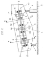
- Fig.1
- eine schematische Seitenansicht einer erfindungsgemäßen Siebvorrichtung
- Fig.2
- eine schematische Seitenansicht einer alternativen Ausführungsform einer erfindungsgemäßen Siebvorrichtung
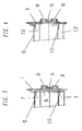
- Fig.3
- eine Schnittansicht entlang Linie AA aus Fig.2
- Fig.4
- eine Schnittansicht entlang Linie BB aus Fig.2
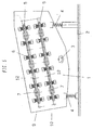
- Fig.5
- eine schematische Seitenansicht einer Mehrdecksiebmaschine gemäß dem Stand der Technik
- Fig.6
- eine Schnittansicht entlang Linie CC aus Fig.5
- Fig.7
- eine Schnittansicht entlang Linie DD aus Fig.5
- Wie aus Fig.1 ersichtlich besteht eine erfindungsgemäße Zwei- oder Mehrdecksiebmaschine aus einem Siebwangen aufweisenden Siebkasten 1 der auf Federn 4 gegenüber einem fixen Untergrund 2 abgestützt wird und einem den Siebkasten 1 in Schwingungen versetzenden Antrieb 3. Dieser ist im vorliegenden Fall als Doppelunwuchtantrieb mit gegenläufigen Unwuchtgewichten ausgebildet, wodurch eine lineare Erregerschwingung erzeugt wird. Prinzipiell sind jedoch alle Arten von Unwuchtantrieben einsetzbar. Fig.2 zeigt beispielsweise den Einsatz eines einfachen Unwuchtantriebs 3, welche den Siebkasten in kreisförmige Schwingungen versetzt.
- Am Siebkasten 1 ist ein einen Schwingrahmen bildendes Schwingsystem angeordnet, welches aus an den Siebwangen des Siebkastens 1 über vorzugsweise elastische Gummiblöcke 8 gelagerten Schubstangen 5 sowie an diesen angeordneten Befestigungsbauteilen 6 besteht. Die Befestigungsbauteile 6 erstrecken sich im wesentlichen rechtwinkelig zur Längsachse der Schubstangen 5 sowie parallel zu den Siebwangen des Siebkastens 1. An den Befestigungsbauteilen 6 sind zwei Schwingrahmenquerträger 7 im wesentlichen untereinander fixiert. Die Schwingrahmenquerträger verbinden einander gegenüberliegende Befestigungsbauteile 6 miteinander.
- Die Siebwangen des Siebkastens 1 sind über Siebkastenquerträger 12 miteinander verbunden.
Die Siebflächen 9,10 werden durch einzelne Siebmatten 11 aufgebaut. Jede Siebmatte 11 ist abwechselnd an einem Schwingrahmenquerträger 7 und einem Siebkastenquerträger 12 befestigt. - Die Befestigung der Schwingrahmenquerträger 7 und Siebkastenquerträger 12 einer Siebfläche 9,10 erfolgt im wesentlichen entlang einer Geraden, so dass sich eine durchgehende im wesentlichen gerade Siebfläche 9,10 ergibt. Abweichungen von einer geraden Siebfläche 9,10 ergeben sich systembedingt aufgrund eines gewissen Durchhangs der einzelnen Siebmatten. Dies ist erforderlich um das Stauchen- und Dehnen der Siebmatten 11 zu ermöglichen.
- Die Funktionsweise der Siebvorrichtung ist wie folgt: der Schwingrahmen wird durch den mittels Unwuchtantrieb 3 in Schwingungen versetzten Siebkasten 1 amplitudenerregt ebenfalls in Schwingungen versetzt. Durch die elastische Lagerung der Schubstangen 5 des Schwingrahmens am Siebkasten 1 entsteht eine zur Grundschwingung des Siebkastens 1 versetzte Schwingung des Schwingrahmens. Durch die abwechselnde Befestigung der Siebmatten 11 am Siebkasten 1 bzw. am Schwingrahmen (Befestigungsbauteile 6) werden die Siebmatten 11 abwechselnd gestaucht und gedehnt. Dies wiederum bewirkt eine optimale Siebwirkung.
- Die erfindungsgemäße Siebvorrichtung zeichnet sich insbesondere dadurch aus, dass sie zwei- bzw. mehrdeckig ist und trotzdem lediglich ein Schwingsystem vorhanden ist. Dadurch ergibt sich der Vorteil, dass die gesamte Vorrichtung sehr niedrig baut, wodurch auch mobile Einsätze möglich sind. Weiters ist die Abstimmung der Schwingsysteme wesentlich einfacher, da lediglich ein System abgestimmt werden muss. Bei einer mehrdeckigen Ausführungsvariante sind entsprechend mehrere Schwingrahmenquerträger 7 an den jeweiligen Befestigungsbauteilen 6 angeordnet.
- Aus Übersichtlichkeitsgründen sind im vorliegenden Ausführungsbeispiel lediglich zwei Siebdecks = Siebflächen 9, 10 verwirklicht. Es liegt jedoch nahe, beliebig viele Siebflächen übereinander angeordnet vorzusehen.
- Zur weiteren Erhöhung der Siebleistung ist vorgesehen, die Fixierung der einzelnen an einem Befestigungsbauteil 6 angeordneten Schwingsystemquerträger 7 in mindestens zwei normal zur Längsachse der Schubstangen 5 verlaufenden Ebenen 14, 15 vorzunehmen. Dabei entsteht ein Versatz "a", der sich nach dem der Siebmaschine zugeführten Aufgabematerial und den Trennschnittgrößen richtet.
- Es ist jedoch auch möglich, die Fixierung der einzelnen an einem Befestigungsbauteil 6 angeordneten Schwingsystemquerträger 7 in einer einzigen normal zur Längsachse der Schubstangen (5) verlaufenden Ebene (13) vorzunehmen.
- Auch die Siebkastenquerträger 12 der einzelnen Siebflächen 9, 10 können entweder jeweils in einer Ebene normal zur Längsachse der Schubstangen 5 angeordnet werden, oder aber mit einem Versatz "a" (siehe Fig.2).
- Das vorliegende Schwingsystem kann auch in Bananenausführung mit kontinuierlich abnehmender Siebdeckneigung ausgeführt werden.
Claims (9)
- Siebmaschine mit einem mittels eines Antriebs in Schwingungen versetzbaren, Siebwangen aufweisenden Siebkasten (1), welcher elastisch, vorzugsweise über Federn (4) auf festem Untergrund (2) abgestützt ist und einem daran elastisch angekoppelten Schwingrahmen, welcher an die Siebwangen elastisch gekoppelte Schubstangen (5) sowie diese verbindende Schwingrahmenquerträger (7) umfasst und eine durch Siebmatten (11) gebildete Siebfläche (9, 10) vorgesehen ist, wobei die Siebmatten (11) durch abwechselnde Befestigung am Siebkasten (1) und am Schwingrahmen zumindest abschnittsweise abwechselnd gestaucht und gedehnt werden, dadurch gekennzeichnet, dass zusätzlich mindestens eine weitere, durch die Siebmatten (11) gebildete Siebfläche (9,10) vorgesehen ist und sämtliche vorhandenen Siebmatten (11) abwechselnd am Siebkasten (1) vorzugsweise an den die Siebwangen verbindenden Siebkastenquerträgern (12) und am Schwingrahmen, vorzugsweise an den Schwingrahmenquerträgern (7) befestigt sind.
- Siebmaschine nach Anspruch 1, dadurch gekennzeichnet, dass die Schubstangen (5) in einem Winkel oder in einem in Förderrichtung abnehmenden Winkel geneigt zum fixen Untergrund (2) verlaufen.
- Siebmaschine nach Anspruch 1 und 2, dadurch gekennzeichnet, dass am Schwingrahmen vorzugsweise an den Schubstangen (5) Befestigungsbauteile (6) vorgesehen sind, welche zur Fixierung der Schwingrahmenquerträger (7) am Schwingrahmen dienen.
- Siebmaschine nach Anspruch 3, dadurch gekennzeichnet, dass mehrere Schwingrahmenquerträger (7) an einem Befestigungsbauteil (6) fixiert sind.
- Siebmaschine nach einem der Ansprüche 1 bis 4, dadurch gekennzeichnet, dass die Befestigungsbauteile (6) im wesentlichen rechtwinkelig, vorzugsweise zu beiden Seiten von den Schubstangen (5) und parallel zu den Siebwangen abstehen.
- Siebmaschine nach einem der Ansprüche 1 bis 5, dadurch gekennzeichnet, dass die Fixierungspunkte der Schwingrahmenquerträger (7) am jeweiligen Befestigungsbauteil (6) in einer normal zur Längsachse der Schubstangen (5) verlaufenden Ebene (13) liegen.
- Siebmaschine nach einem der Ansprüche 1 bis 6, dadurch gekennzeichnet, dass die Fixierungspunkte der Schwingrahmenquerträger (7) am jeweiligen Befestigungsbauteil (6) in mindestens zwei normal zur Längsachse der Schubstangen (5) verlaufenden Ebenen (14,15) liegen.
- Siebmaschine nach einem der Ansprüche 1 bis 7, dadurch gekennzeichnet, dass die durch die Siebmatten (11) gebildeten Siebflächen (9,10) im wesentlichen parallel zueinander verlaufen.
- Siebmaschine nach einem der Ansprüche 1 bis 8, dadurch gekennzeichnet, dass die Schwingrahmenquerträger (7) an jedem Befestigungsbauteil (6) zu beiden Seiten der jeweiligen Schubstangen (5) angeordnet sind
Applications Claiming Priority (2)
| Application Number | Priority Date | Filing Date | Title |
|---|---|---|---|
| AT0060602U AT6073U1 (de) | 2002-09-12 | 2002-09-12 | Mehrdecksiebmaschine |
| AT60602U | 2002-09-12 |
Publications (2)
| Publication Number | Publication Date |
|---|---|
| EP1398085A1 EP1398085A1 (de) | 2004-03-17 |
| EP1398085B1 true EP1398085B1 (de) | 2007-05-30 |
Family
ID=3495026
Family Applications (1)
| Application Number | Title | Priority Date | Filing Date |
|---|---|---|---|
| EP03450201A Expired - Lifetime EP1398085B1 (de) | 2002-09-12 | 2003-09-09 | Mehrdecksiebmaschine |
Country Status (8)
| Country | Link |
|---|---|
| US (1) | US7114620B2 (de) |
| EP (1) | EP1398085B1 (de) |
| AT (2) | AT6073U1 (de) |
| AU (1) | AU2003241634A1 (de) |
| DE (1) | DE50307359D1 (de) |
| DK (1) | DK1398085T3 (de) |
| ES (1) | ES2287443T3 (de) |
| HR (1) | HRP20030722B1 (de) |
Cited By (2)
| Publication number | Priority date | Publication date | Assignee | Title |
|---|---|---|---|---|
| CN110756431A (zh) * | 2019-10-23 | 2020-02-07 | 淮南市久祥米业有限公司 | 一种大米分级振动筛 |
| CN112044755A (zh) * | 2020-10-09 | 2020-12-08 | 陈媛媛 | 一种环保型振动筛 |
Families Citing this family (34)
| Publication number | Priority date | Publication date | Assignee | Title |
|---|---|---|---|---|
| US8436268B1 (en) | 2002-08-12 | 2013-05-07 | Ecullet | Method of and apparatus for type and color sorting of cullet |
| DE102007003359A1 (de) * | 2007-01-17 | 2008-07-31 | Haver & Boecker Ohg | Schwingsiebmaschine |
| US7861866B1 (en) * | 2008-03-07 | 2011-01-04 | Tema Isenmann, Inc. | Screening system with knocking device |
| US20120199519A1 (en) | 2009-06-09 | 2012-08-09 | Waste Systems Limited | Waste screening apparatus and methods |
| US8757392B2 (en) * | 2011-11-23 | 2014-06-24 | Action Vibratory Equipment, Inc. | Flexible mat screening apparatus with offset supports |
| US9205459B2 (en) * | 2012-08-28 | 2015-12-08 | Terex Usa, Llc | Vibrating screen deck deflector systems and methods |
| WO2014177910A1 (en) * | 2013-04-30 | 2014-11-06 | Flsmidth A/S | Vibrating screen |
| CN107020232A (zh) * | 2017-04-26 | 2017-08-08 | 新乡市振英机械设备有限公司 | 一种自动化防尘分级振动筛 |
| CN107983628A (zh) * | 2017-12-12 | 2018-05-04 | 安徽省达亿粮油食品有限公司 | 一种面粉除杂装置 |
| CN108325815A (zh) * | 2017-12-20 | 2018-07-27 | 广西澜光科技有限公司 | 一种多级谷物振动分选机构 |
| CN108160471A (zh) * | 2017-12-25 | 2018-06-15 | 郑州丽福爱生物技术有限公司 | 一种平铺式饲料多级筛分装置 |
| CN108704840B (zh) * | 2018-06-22 | 2024-03-29 | 镇江宝塑高分子材料有限公司 | 一种用于tpu聚氨酯弹性体生产的振动筛专用筛板 |
| CN109046932A (zh) * | 2018-07-27 | 2018-12-21 | 卢若望 | 一种节能减震型筛料箱 |
| CN109127366A (zh) * | 2018-08-09 | 2019-01-04 | 天津中科福源科技有限责任公司 | 一种贝壳粉生产用筛选装置 |
| CN109174627B (zh) * | 2018-10-29 | 2023-04-25 | 天津绿之本生物科技有限公司 | 一种有机肥筛分机 |
| CN110170445B (zh) * | 2019-05-31 | 2024-06-28 | 厦门大学嘉庚学院 | 一种脚踏式试验筛装置及其使用方法 |
| CN110711695A (zh) * | 2019-11-10 | 2020-01-21 | 江苏九洲环保技术有限公司 | 一种聚烯烃母粒分粒振动筛 |
| CN111589706B (zh) * | 2020-04-16 | 2022-05-17 | 天地(唐山)矿业科技有限公司 | 一种干法选煤的细粒级颗粒群同台分级与分选装置 |
| CN112871287A (zh) * | 2021-01-13 | 2021-06-01 | 陈航平 | 一种防止原料粘附的高效化工用的化工原料处理设备 |
| CN112774980B (zh) * | 2021-01-18 | 2023-08-08 | 肇庆市和盛塑胶有限公司 | 一种可大小分开的资源再生用塑料颗粒收集装置 |
| CN113731793B (zh) * | 2021-09-15 | 2022-12-09 | 云南茗杨天下绿色食品有限公司 | 一种普洱茶膏低温萃取智能冻干生产线 |
| CN113996527A (zh) * | 2021-10-19 | 2022-02-01 | 李洪山 | 一种公路施工用石子筛选器 |
| CN114226223A (zh) * | 2021-11-02 | 2022-03-25 | 佛山市交通科技有限公司 | 沥青混合料筛分装置 |
| CN115213091B (zh) * | 2021-12-31 | 2023-07-18 | 湖南凯地众能科技有限公司 | 一种用于废旧电池回收的分拣装置 |
| CN114377948B (zh) * | 2022-01-13 | 2022-09-20 | 中国矿业大学(北京) | 一种模块化可重构横向振动大型弛张筛 |
| CN114472156A (zh) * | 2022-03-10 | 2022-05-13 | 山丹县农业技术推广中心 | 一种农业技术推广用种子筛选装置 |
| CN114602796B (zh) * | 2022-03-24 | 2023-04-28 | 衡阳市建衡实业有限公司 | 一种明矾颗粒分离用筛选设备 |
| CN114985256B (zh) * | 2022-06-07 | 2023-04-07 | 宿州郑升轴承有限公司 | 一种轴承筛分设备及其工作方法 |
| CN115463829B (zh) * | 2022-08-09 | 2024-10-22 | 醴陵市沃美陶瓷科技有限公司 | 一种新型多功能陶瓷过滤机 |
| CN115254593A (zh) * | 2022-08-10 | 2022-11-01 | 安徽捷迅光电技术有限公司 | 一种去除杂质的茶叶精选机 |
| CN115180196B (zh) * | 2022-08-24 | 2023-07-11 | 广东一味鲜食品有限公司 | 一种块状调味品自动化包装控制系统及方法 |
| CN115635525A (zh) * | 2022-12-26 | 2023-01-24 | 黄元御(潍坊)生物科技有限公司 | 一种药材切割装置 |
| CN116460031A (zh) * | 2023-04-24 | 2023-07-21 | 中南大学 | 一种霍普金森压杆试验的碎屑分级收集装置及其收集方法 |
| CN119777225B (zh) * | 2025-03-11 | 2025-05-13 | 山西建筑工程集团有限公司 | 一种足球运动场草坪施工设备及施工方法 |
Family Cites Families (16)
| Publication number | Priority date | Publication date | Assignee | Title |
|---|---|---|---|---|
| US177252A (en) * | 1876-05-09 | Improvement in grain-separators | ||
| US385427A (en) * | 1888-07-03 | Grain separator and grader | ||
| US1923229A (en) * | 1931-03-07 | 1933-08-22 | Robins Conveying Belt Co | Screening apparatus |
| DE1204920B (de) | 1963-01-05 | 1965-11-11 | Albert Wehner | Sieb- oder Foerdermaschine |
| DE1206372B (de) * | 1964-09-26 | 1965-12-09 | Albert Wehner | Siebrost |
| DE1275339B (de) | 1967-07-13 | 1968-08-14 | Albert Wehner | Siebmaschine |
| DE2216130A1 (de) | 1972-04-01 | 1973-10-04 | Albert Wehner | Sieb- oder foerdermaschine |
| US4188288A (en) * | 1972-11-30 | 1980-02-12 | Hein, Lehmann Ag | Screen with tubular frame systems coupled for rectilinear motion |
| DE2429733A1 (de) | 1974-06-21 | 1976-01-08 | Albert Wehner | Vorrichtung zum sichten, filtern, waschen od. dgl. |
| SE435585B (sv) * | 1983-05-16 | 1984-10-08 | Kmw Mekan Ab | Sallanordning |
| AT379088B (de) | 1984-02-10 | 1985-11-11 | Binder Co Ag | Siebvorrichtung |
| DE3524895C1 (de) * | 1985-07-12 | 1986-12-18 | Hein, Lehmann AG, 4000 Düsseldorf | Siebmaschine |
| GB2221406B (en) | 1988-08-12 | 1992-05-27 | Vni Pi Mekh Obrabotki | Vibratory screening machine |
| ZA914947B (en) | 1990-06-29 | 1992-03-25 | Bengston N V | Composite vibratory screen |
| US5341939A (en) * | 1993-02-22 | 1994-08-30 | Corrosion Engineering, Inc. | Multiple deck vibrating screen apparatus |
| DE10016979C1 (de) * | 2000-04-06 | 2001-08-30 | Joest Gmbh & Co Kg | Siebvorrichtung |
-
2002
- 2002-09-12 AT AT0060602U patent/AT6073U1/de not_active IP Right Cessation
-
2003
- 2003-08-26 AU AU2003241634A patent/AU2003241634A1/en not_active Abandoned
- 2003-08-29 US US10/652,548 patent/US7114620B2/en not_active Expired - Lifetime
- 2003-09-09 AT AT03450201T patent/ATE363344T1/de active
- 2003-09-09 ES ES03450201T patent/ES2287443T3/es not_active Expired - Lifetime
- 2003-09-09 EP EP03450201A patent/EP1398085B1/de not_active Expired - Lifetime
- 2003-09-09 DE DE50307359T patent/DE50307359D1/de not_active Expired - Lifetime
- 2003-09-09 DK DK03450201T patent/DK1398085T3/da active
- 2003-09-10 HR HR20030722A patent/HRP20030722B1/xx not_active IP Right Cessation
Cited By (2)
| Publication number | Priority date | Publication date | Assignee | Title |
|---|---|---|---|---|
| CN110756431A (zh) * | 2019-10-23 | 2020-02-07 | 淮南市久祥米业有限公司 | 一种大米分级振动筛 |
| CN112044755A (zh) * | 2020-10-09 | 2020-12-08 | 陈媛媛 | 一种环保型振动筛 |
Also Published As
| Publication number | Publication date |
|---|---|
| ES2287443T3 (es) | 2007-12-16 |
| HRP20030722A2 (en) | 2004-06-30 |
| HRP20030722B1 (en) | 2008-07-31 |
| AU2003241634A1 (en) | 2004-04-01 |
| DK1398085T3 (da) | 2007-08-20 |
| DE50307359D1 (de) | 2007-07-12 |
| ATE363344T1 (de) | 2007-06-15 |
| US20040050757A1 (en) | 2004-03-18 |
| US7114620B2 (en) | 2006-10-03 |
| AT6073U1 (de) | 2003-04-25 |
| EP1398085A1 (de) | 2004-03-17 |
Similar Documents
| Publication | Publication Date | Title |
|---|---|---|
| EP1398085A1 (de) | Mehrdecksiebmaschine | |
| EP0155527B1 (de) | Vorrichtung zum Putzen von Griessen | |
| DE102012206347B4 (de) | Siebvorrichtung | |
| DE202014008855U1 (de) | Siebmaschine mit Antrieb | |
| EP1480763B1 (de) | Siebvorrichtung | |
| AT516406B1 (de) | Vorrichtung zum Trennen von Grobkorn von kleineren Korngrößen | |
| DE3139279A1 (de) | Schwingmaschine zum sieben und/oder foerdern, insbesondere einmassen-freischwinger-maschine | |
| EP3409382B1 (de) | Spannwellensiebmaschine | |
| DE202016103754U1 (de) | Siebmaschine | |
| DE3741966C2 (de) | ||
| EP3714996A1 (de) | Siebvorrichtung | |
| EP0405477A1 (de) | Siebmaschine | |
| EP0197191A2 (de) | Siebmaschine mit einem flexiblen Siebbelag | |
| EP0350830A2 (de) | Siebmaschine | |
| DE2923662C2 (de) | Schwingsieb, insbesondere Kreisschwingsieb | |
| DE102014110055B4 (de) | Siebmaschine mit kassettenartigen Siebflächenabschnitten | |
| EP0028792A2 (de) | Mehrdecksiebmaschine | |
| EP1224984B1 (de) | Sieb und Plansichter | |
| EP1228814A2 (de) | Siebmaschine | |
| AT400533B (de) | Spannwellensieb | |
| EP0096270B1 (de) | Siebmaschine | |
| DE602004011125T2 (de) | Strukturelle anordnung für schwingeinrichtungen | |
| EP3917690B1 (de) | Schwingsiebanlage, bestehend aus wenigstens zwei in reihe angeordneten siebmaschinen | |
| EP0099528A2 (de) | Siebmaschine | |
| AT389062B (de) | Siebvorrichtung |
Legal Events
| Date | Code | Title | Description |
|---|---|---|---|
| PUAI | Public reference made under article 153(3) epc to a published international application that has entered the european phase |
Free format text: ORIGINAL CODE: 0009012 |
|
| AK | Designated contracting states |
Kind code of ref document: A1 Designated state(s): AT BE BG CH CY CZ DE DK EE ES FI FR GB GR HU IE IT LI LU MC NL PT RO SE SI SK TR |
|
| AX | Request for extension of the european patent |
Extension state: AL LT LV MK |
|
| 17P | Request for examination filed |
Effective date: 20040917 |
|
| AKX | Designation fees paid |
Designated state(s): AT BE BG CH CY CZ DE DK EE ES FI FR GB GR HU IE IT LI LU MC NL PT RO SE SI SK TR |
|
| REG | Reference to a national code |
Ref country code: HK Ref legal event code: DE Ref document number: 1064983 Country of ref document: HK |
|
| GRAP | Despatch of communication of intention to grant a patent |
Free format text: ORIGINAL CODE: EPIDOSNIGR1 |
|
| GRAS | Grant fee paid |
Free format text: ORIGINAL CODE: EPIDOSNIGR3 |
|
| GRAA | (expected) grant |
Free format text: ORIGINAL CODE: 0009210 |
|
| AK | Designated contracting states |
Kind code of ref document: B1 Designated state(s): AT BE BG CH CY CZ DE DK EE ES FI FR GB GR HU IE IT LI LU MC NL PT RO SE SI SK TR |
|
| PG25 | Lapsed in a contracting state [announced via postgrant information from national office to epo] |
Ref country code: FI Free format text: LAPSE BECAUSE OF FAILURE TO SUBMIT A TRANSLATION OF THE DESCRIPTION OR TO PAY THE FEE WITHIN THE PRESCRIBED TIME-LIMIT Effective date: 20070530 |
|
| REG | Reference to a national code |
Ref country code: GB Ref legal event code: FG4D Free format text: NOT ENGLISH |
|
| REG | Reference to a national code |
Ref country code: CH Ref legal event code: EP |
|
| REG | Reference to a national code |
Ref country code: IE Ref legal event code: FG4D Free format text: LANGUAGE OF EP DOCUMENT: GERMAN |
|
| REF | Corresponds to: |
Ref document number: 50307359 Country of ref document: DE Date of ref document: 20070712 Kind code of ref document: P |
|
| REG | Reference to a national code |
Ref country code: DE Ref legal event code: R096 Ref document number: 50307359 Country of ref document: DE Effective date: 20070712 |
|
| REG | Reference to a national code |
Ref country code: CH Ref legal event code: NV Representative=s name: PATENTANWAELTE SCHAAD, BALASS, MENZL & PARTNER AG |
|
| REG | Reference to a national code |
Ref country code: DK Ref legal event code: T3 |
|
| PG25 | Lapsed in a contracting state [announced via postgrant information from national office to epo] |
Ref country code: SE Free format text: LAPSE BECAUSE OF FAILURE TO SUBMIT A TRANSLATION OF THE DESCRIPTION OR TO PAY THE FEE WITHIN THE PRESCRIBED TIME-LIMIT Effective date: 20070830 |
|
| ET | Fr: translation filed | ||
| GBT | Gb: translation of ep patent filed (gb section 77(6)(a)/1977) |
Effective date: 20071022 |
|
| REG | Reference to a national code |
Ref country code: ES Ref legal event code: FG2A Ref document number: 2287443 Country of ref document: ES Kind code of ref document: T3 |
|
| PG25 | Lapsed in a contracting state [announced via postgrant information from national office to epo] |
Ref country code: PT Free format text: LAPSE BECAUSE OF FAILURE TO SUBMIT A TRANSLATION OF THE DESCRIPTION OR TO PAY THE FEE WITHIN THE PRESCRIBED TIME-LIMIT Effective date: 20071030 Ref country code: SI Free format text: LAPSE BECAUSE OF FAILURE TO SUBMIT A TRANSLATION OF THE DESCRIPTION OR TO PAY THE FEE WITHIN THE PRESCRIBED TIME-LIMIT Effective date: 20070530 |
|
| PLBE | No opposition filed within time limit |
Free format text: ORIGINAL CODE: 0009261 |
|
| STAA | Information on the status of an ep patent application or granted ep patent |
Free format text: STATUS: NO OPPOSITION FILED WITHIN TIME LIMIT |
|
| PG25 | Lapsed in a contracting state [announced via postgrant information from national office to epo] |
Ref country code: GR Free format text: LAPSE BECAUSE OF FAILURE TO SUBMIT A TRANSLATION OF THE DESCRIPTION OR TO PAY THE FEE WITHIN THE PRESCRIBED TIME-LIMIT Effective date: 20070831 Ref country code: MC Free format text: LAPSE BECAUSE OF NON-PAYMENT OF DUE FEES Effective date: 20070930 Ref country code: IT Free format text: LAPSE BECAUSE OF FAILURE TO SUBMIT A TRANSLATION OF THE DESCRIPTION OR TO PAY THE FEE WITHIN THE PRESCRIBED TIME-LIMIT Effective date: 20070530 |
|
| 26N | No opposition filed |
Effective date: 20080303 |
|
| PG25 | Lapsed in a contracting state [announced via postgrant information from national office to epo] |
Ref country code: RO Free format text: LAPSE BECAUSE OF FAILURE TO SUBMIT A TRANSLATION OF THE DESCRIPTION OR TO PAY THE FEE WITHIN THE PRESCRIBED TIME-LIMIT Effective date: 20070530 |
|
| REG | Reference to a national code |
Ref country code: DE Ref legal event code: R097 Ref document number: 50307359 Country of ref document: DE Effective date: 20080303 |
|
| PG25 | Lapsed in a contracting state [announced via postgrant information from national office to epo] |
Ref country code: EE Free format text: LAPSE BECAUSE OF FAILURE TO SUBMIT A TRANSLATION OF THE DESCRIPTION OR TO PAY THE FEE WITHIN THE PRESCRIBED TIME-LIMIT Effective date: 20070530 |
|
| PG25 | Lapsed in a contracting state [announced via postgrant information from national office to epo] |
Ref country code: CY Free format text: LAPSE BECAUSE OF FAILURE TO SUBMIT A TRANSLATION OF THE DESCRIPTION OR TO PAY THE FEE WITHIN THE PRESCRIBED TIME-LIMIT Effective date: 20070530 |
|
| PG25 | Lapsed in a contracting state [announced via postgrant information from national office to epo] |
Ref country code: LU Free format text: LAPSE BECAUSE OF NON-PAYMENT OF DUE FEES Effective date: 20070909 |
|
| PG25 | Lapsed in a contracting state [announced via postgrant information from national office to epo] |
Ref country code: TR Free format text: LAPSE BECAUSE OF FAILURE TO SUBMIT A TRANSLATION OF THE DESCRIPTION OR TO PAY THE FEE WITHIN THE PRESCRIBED TIME-LIMIT Effective date: 20070530 Ref country code: HU Free format text: LAPSE BECAUSE OF FAILURE TO SUBMIT A TRANSLATION OF THE DESCRIPTION OR TO PAY THE FEE WITHIN THE PRESCRIBED TIME-LIMIT Effective date: 20071201 |
|
| PG25 | Lapsed in a contracting state [announced via postgrant information from national office to epo] |
Ref country code: BG Free format text: LAPSE BECAUSE OF NON-PAYMENT OF DUE FEES Effective date: 20080930 |
|
| REG | Reference to a national code |
Ref country code: HK Ref legal event code: WD Ref document number: 1064983 Country of ref document: HK |
|
| PG25 | Lapsed in a contracting state [announced via postgrant information from national office to epo] |
Ref country code: BG Free format text: LAPSE BECAUSE OF NON-PAYMENT OF DUE FEES Effective date: 20070930 |
|
| REG | Reference to a national code |
Ref country code: FR Ref legal event code: PLFP Year of fee payment: 13 |
|
| REG | Reference to a national code |
Ref country code: FR Ref legal event code: PLFP Year of fee payment: 14 |
|
| REG | Reference to a national code |
Ref country code: FR Ref legal event code: PLFP Year of fee payment: 15 |
|
| REG | Reference to a national code |
Ref country code: FR Ref legal event code: PLFP Year of fee payment: 16 |
|
| PGFP | Annual fee paid to national office [announced via postgrant information from national office to epo] |
Ref country code: NL Payment date: 20190926 Year of fee payment: 17 Ref country code: DK Payment date: 20190924 Year of fee payment: 17 Ref country code: IE Payment date: 20190923 Year of fee payment: 17 Ref country code: CZ Payment date: 20190905 Year of fee payment: 17 Ref country code: SK Payment date: 20190830 Year of fee payment: 17 |
|
| PGFP | Annual fee paid to national office [announced via postgrant information from national office to epo] |
Ref country code: BE Payment date: 20190926 Year of fee payment: 17 |
|
| PGFP | Annual fee paid to national office [announced via postgrant information from national office to epo] |
Ref country code: CH Payment date: 20190925 Year of fee payment: 17 |
|
| REG | Reference to a national code |
Ref country code: DK Ref legal event code: EBP Effective date: 20200930 |
|
| PG25 | Lapsed in a contracting state [announced via postgrant information from national office to epo] |
Ref country code: CZ Free format text: LAPSE BECAUSE OF NON-PAYMENT OF DUE FEES Effective date: 20200909 |
|
| REG | Reference to a national code |
Ref country code: CH Ref legal event code: PL |
|
| REG | Reference to a national code |
Ref country code: NL Ref legal event code: MM Effective date: 20201001 |
|
| REG | Reference to a national code |
Ref country code: SK Ref legal event code: MM4A Ref document number: E 2354 Country of ref document: SK Effective date: 20200909 |
|
| REG | Reference to a national code |
Ref country code: BE Ref legal event code: MM Effective date: 20200930 |
|
| PG25 | Lapsed in a contracting state [announced via postgrant information from national office to epo] |
Ref country code: NL Free format text: LAPSE BECAUSE OF NON-PAYMENT OF DUE FEES Effective date: 20201001 |
|
| PG25 | Lapsed in a contracting state [announced via postgrant information from national office to epo] |
Ref country code: SK Free format text: LAPSE BECAUSE OF NON-PAYMENT OF DUE FEES Effective date: 20200909 |
|
| PG25 | Lapsed in a contracting state [announced via postgrant information from national office to epo] |
Ref country code: LI Free format text: LAPSE BECAUSE OF NON-PAYMENT OF DUE FEES Effective date: 20200930 Ref country code: IE Free format text: LAPSE BECAUSE OF NON-PAYMENT OF DUE FEES Effective date: 20200909 Ref country code: CH Free format text: LAPSE BECAUSE OF NON-PAYMENT OF DUE FEES Effective date: 20200930 Ref country code: BE Free format text: LAPSE BECAUSE OF NON-PAYMENT OF DUE FEES Effective date: 20200930 |
|
| PG25 | Lapsed in a contracting state [announced via postgrant information from national office to epo] |
Ref country code: DK Free format text: LAPSE BECAUSE OF NON-PAYMENT OF DUE FEES Effective date: 20200930 |
|
| PGFP | Annual fee paid to national office [announced via postgrant information from national office to epo] |
Ref country code: GB Payment date: 20220920 Year of fee payment: 20 Ref country code: DE Payment date: 20220929 Year of fee payment: 20 Ref country code: AT Payment date: 20220927 Year of fee payment: 20 |
|
| PGFP | Annual fee paid to national office [announced via postgrant information from national office to epo] |
Ref country code: FR Payment date: 20220926 Year of fee payment: 20 |
|
| PGFP | Annual fee paid to national office [announced via postgrant information from national office to epo] |
Ref country code: ES Payment date: 20221013 Year of fee payment: 20 |
|
| P01 | Opt-out of the competence of the unified patent court (upc) registered |
Effective date: 20230517 |
|
| REG | Reference to a national code |
Ref country code: DE Ref legal event code: R071 Ref document number: 50307359 Country of ref document: DE |
|
| REG | Reference to a national code |
Ref country code: ES Ref legal event code: FD2A Effective date: 20230926 |
|
| REG | Reference to a national code |
Ref country code: GB Ref legal event code: PE20 Expiry date: 20230908 |
|
| REG | Reference to a national code |
Ref country code: AT Ref legal event code: MK07 Ref document number: 363344 Country of ref document: AT Kind code of ref document: T Effective date: 20230909 |
|
| PG25 | Lapsed in a contracting state [announced via postgrant information from national office to epo] |
Ref country code: GB Free format text: LAPSE BECAUSE OF EXPIRATION OF PROTECTION Effective date: 20230908 Ref country code: ES Free format text: LAPSE BECAUSE OF EXPIRATION OF PROTECTION Effective date: 20230910 |