EP1396408B1 - Dispositif d'entraînement d'une poulie de renvoi d'un télésiège mono câble à pinces fixes - Google Patents
Dispositif d'entraînement d'une poulie de renvoi d'un télésiège mono câble à pinces fixes Download PDFInfo
- Publication number
- EP1396408B1 EP1396408B1 EP03354068A EP03354068A EP1396408B1 EP 1396408 B1 EP1396408 B1 EP 1396408B1 EP 03354068 A EP03354068 A EP 03354068A EP 03354068 A EP03354068 A EP 03354068A EP 1396408 B1 EP1396408 B1 EP 1396408B1
- Authority
- EP
- European Patent Office
- Prior art keywords
- pulley
- wheel
- motor
- bull
- chair lift
- Prior art date
- Legal status (The legal status is an assumption and is not a legal conclusion. Google has not performed a legal analysis and makes no representation as to the accuracy of the status listed.)
- Expired - Lifetime
Links
- 230000007246 mechanism Effects 0.000 claims abstract description 21
- 239000003638 chemical reducing agent Substances 0.000 claims description 7
- 230000005611 electricity Effects 0.000 claims 1
- 230000005540 biological transmission Effects 0.000 description 4
- 230000009467 reduction Effects 0.000 description 3
- 230000008878 coupling Effects 0.000 description 2
- 238000010168 coupling process Methods 0.000 description 2
- 238000005859 coupling reaction Methods 0.000 description 2
- 210000000056 organ Anatomy 0.000 description 2
- 238000005096 rolling process Methods 0.000 description 2
- 230000009471 action Effects 0.000 description 1
- 238000006073 displacement reaction Methods 0.000 description 1
- 238000009434 installation Methods 0.000 description 1
- 239000002184 metal Substances 0.000 description 1
- 238000011144 upstream manufacturing Methods 0.000 description 1
Images


Classifications
-
- B—PERFORMING OPERATIONS; TRANSPORTING
- B61—RAILWAYS
- B61B—RAILWAY SYSTEMS; EQUIPMENT THEREFOR NOT OTHERWISE PROVIDED FOR
- B61B12/00—Component parts, details or accessories not provided for in groups B61B7/00 - B61B11/00
- B61B12/10—Cable traction drives
-
- B—PERFORMING OPERATIONS; TRANSPORTING
- B61—RAILWAYS
- B61B—RAILWAY SYSTEMS; EQUIPMENT THEREFOR NOT OTHERWISE PROVIDED FOR
- B61B12/00—Component parts, details or accessories not provided for in groups B61B7/00 - B61B11/00
- B61B12/007—Cable tensioning devices
Definitions
- the invention relates to a lift-carrying aerial cable-lift conveyor with fixed seat-retaining clips, comprising a return pulley over which the cable passes, and means for positioning the vertical-axis pulley on a carriage mounted in the seat.
- the station on a support device for use as a driving pulley driven by a geared motor mechanism, and / or as a tension pulley.
- the vertical axis drive pulley of the single-cable fixed chairlifts is conventionally rotated by a conical torque transmission system allowing a right-angle return of a rotational movement from a geared motor arranged horizontally on a platform elevated from the station.
- the implementation of such a kinematic transmission chain is complicated, and requires significant longitudinal congestion in the station.
- the diversity of subsets, and the time of assembly and adjustment of equipment, increase the number of stakeholders and the cost of these known installations.
- the object of the invention is to provide a single-cable fixed chairlift station of simplified structure with reduced longitudinal dimensions, using a maximum of standard mechanical components depending on the type of station to be equipped, and independently of the use of a driving pulley or a tension pulley.
- the geared motor mechanism comprises a line of coaxial shafts extending perpendicularly to the return pulley in a substantially vertical direction.
- the geared motor mechanism is composed of an electric motor and a mechanical gearbox constituting two independent modules arranged on either side of the return pulley.
- the first high-speed motor output shaft passes through a sheath tubular integral with the carriage, and is surrounded coaxially by the second low speed hollow output shaft of the reducer.
- the in-line modular assembly of shafts of the geared motor mechanism makes it possible to obtain a short kinematic chain without the need for inter-linkage transmission means of the conical torque type.
- Such a direct drive leads to a reduction in the assembly time and the longitudinal size of the station.
- the motor can be equipped with an electronic speed switch for the direct drive of the vertical axis pulley.
- an aerial tractor-carrying cable 10 of a chairlift passes around a vertical axis pulley 12 housed in a station or end station 14.
- the cable 10 extends in an endless loop along a uplink, and a descending lane, and the seats, one of which 16 is depicted on the figure 2 are hooked to the cable 10 at regular intervals by fixed retaining clips 18.
- Station 14 illustrated at figure 1 is a driving downstream station, in which the horizontal idler pulley 12 is rotated by a geared motor mechanism 20 extending perpendicular to the pulley 12, the assembly being carried by a support device 22 with a predetermined height offset .
- the support device 22 is composed of a fixed concrete base 24 anchored to the ground, and a horizontal metal frame 26 comprising fixed profiles 28 in l, and a carriage 30 mounted in horizontal translation through organs rolling 32.
- the pulley 12 and the geared motor mechanism 20 are mounted on one of the ends of the carriage 30.
- the longitudinal travel of the carriage 30 extends over a length of about 3 meters between the positions A and B of the figure 3 , to ensure the tension of the cable 10.
- a tensioning device formed for example by a jack 66 or a counterweight, is associated with the carriage so as to act in the direction of the line.
- the geared motor mechanism 20 comprises an electric motor 34 disposed under the pulley 12, and a speed reducer 36 arranged above the pulley 12, and aligned coaxially with the motor 34.
- the vertical output shaft of the motor 34 is provided with of a flywheel 37 of inertia, and passes through a tubular sleeve 38 secured to the carriage 30, so as to constitute the shaft 40 at high speed coupled to the input of the gearbox 36.
- the mechanical gearbox 36 is provided with several stages of reduction gears 42 and an output shaft 44 at a low speed for driving the pulley 12 in rotation.
- a pair of bearings 46 is interposed coaxially between the fixed sleeve 38 and a cylindrical bore 48 of the hub 50 of the pulley 12.
- the output shaft 44 of the gearbox 36 is hollow, and is coupled directly to a drive sleeve 52 fixed to the hub 50 by screws and 54 pieces of assembly.
- the housing of the gearbox 36 is supported by a pair of torque arms 55.
- the two shafts 40, 44 are coaxial extending perpendicularly with respect to the pulley 12.
- the modular in-line shaft assembly of the geared motor mechanism 20 makes it possible to obtain a short kinematic chain without the need for inter-torque transmission means of the torque type. conical.
- the drive structure according to the invention makes it possible to reduce the assembly time as well as the longitudinal space requirement of the station 14.
- a roller train 56 is mounted on a rocker arm 58 articulated at the inlet of the station 14 around a transverse axis 60 so as to deflect the cable 10 downwards toward the pulley 12.
- a spare gear wheel 62 is rigidly fixed to the underside of the pulley 12 to cooperate with an emergency engine 64 integral with the carriage 30.
- the emergency engine 64 may an electric geared motor driven by a generator, or a hydraulic motor.
- the return pulley 12 can thus be rotated by the emergency engine 64 in case of intervention on the geared motor mechanism 20.
- the mounting of the pulley 12 on the movable carriage 30, and the use of standard elements to constitute the geared motor mechanism 20, allow to obtain a modularity of the subassemblies of chairlift stations.
- the pulley 12 is a driving pulley rotated by the geared motor mechanism 20.
- the pulley 12 can also be transformed into a simple tension pulley, for example for the upstream station of the chairlift.
- the electric motor 34 and the gearbox 36 are not mounted. It is sufficient to remove the coupling connection of the gearbox 36 and the electric motor 34 with the pulley 12. Sliding under the action of the jack 66 of the tensioning device acting in the direction of the line, the carriage 30 holds the cable 10 in position. constant under constant voltage.
- the motor can be equipped with an electronic speed switch for the direct drive of the vertical axis pulley.
Landscapes
- Engineering & Computer Science (AREA)
- Transportation (AREA)
- Mechanical Engineering (AREA)
- Devices For Conveying Motion By Means Of Endless Flexible Members (AREA)
- Emergency Lowering Means (AREA)
- Pulleys (AREA)
- Forwarding And Storing Of Filamentary Material (AREA)
- Automobile Manufacture Line, Endless Track Vehicle, Trailer (AREA)
- Gear Transmission (AREA)
- Transmission Devices (AREA)
Description
- L'invention concerne un télésiège de transport à câble aérien porteur-tracteur et à pinces fixes de retenue des sièges, comprenant une poulie de renvoi sur laquelle passe le câble, et des moyens de positionnement de la poulie à axe vertical sur un chariot monté dans la station sur un dispositif de support pour une utilisation en poulie motrice entraînée par un mécanisme motoréducteur, et/ou en poulie de tension.
- La poulie motrice à axe vertical des télésièges fixes monocâble est classiquement entraînée en rotation par un système de transmission à couple conique permettant un renvoi à angle droit d'un mouvement de rotation en provenance d'un motoréducteur disposé horizontalement sur une plateforme surélevée de la station. La mise en oeuvre d'une telle chaîne cinématique de transmission est compliquée, et nécessite un encombrement longitudinal important dans la station. La diversité des sous-ensembles, et le temps de montage et de réglage des équipements, augmentent le nombre d'intervenants et le prix de revient de ces installations connues.
- L'invention a pour but de permettre la réalisation d'une station de télésiège fixe monocâble de structure simplifiée et à encombrement longitudinal réduit, utilisant un maximum de composants mécaniques standards selon le type de gares à équiper, et indépendamment de l'utilisation d'une poulie motrice ou d'une poulie de tension.
- Selon l'invention, ce but est atteint par le fait que le mécanisme motoréducteur comporte une ligne d'arbres coaxiaux s'étendant perpendiculairement à la poulie de renvoi selon une direction sensiblement verticale.
- Selon un mode de réalisation préférentiel, le mécanisme motoréducteur est composé d'un moteur électrique et d'un réducteur mécanique constituant deux modules indépendants disposés de part et d'autre de la poulie de renvoi. Le premier arbre de sortie à grande vitesse du moteur traverse un fourreau tubulaire solidaire du chariot, et est entouré coaxialement par le deuxième arbre de sortie creux à petite vitesse du réducteur.
- Le montage modulaire en ligne d'arbres du mécanisme motoréducteur permet d'obtenir une chaîne cinématique courte sans nécessiter des moyens de transmission intercalaires du type couple conique. Un tel entraînement direct entraîne une réduction du temps de montage, et de l'encombrement longitudinal de la station.
- D'autres caractéristiques peuvent être utilisées isolément ou en combinaison :
- le moyeu de la poulie tourne autour du fourreau avec interposition de roulements, et comporte un manchon d'entraînement relié au deuxième arbre rotatif du réducteur ;
- le réducteur mécanique à engrenages de démultiplication est situé au-dessus de la poulie, et à l'opposé du moteur électrique par rapport à la direction verticale ;
- le mécanisme motoréducteur comprend un moteur équipé d'un commutateur électronique de vitesse pour l'entraînement direct de la poulie ;
- la poulie est dotée d'une roue dentée susceptible de coopérer avec un moteur de secours solidaire du chariot ;
- le dispositif de support comprend un socle supportant des profilés fixes horizontaux le long desquels se déplace le chariot par l'intermédiaire d'organes de roulement ;
- le chariot de support de la poulie de renvoi est associé à un dispositif tendeur agissant dans la direction de la ligne pour la mise sous tension mécanique du câble.
- Selon une variante sans réducteur mécanique, le moteur peut être équipé d'un commutateur électronique de vitesse pour l'entraînement direct de la poulie à axe vertical.
- D'autres avantages et caractéristiques ressortiront plus clairement de la description qui va suivre d'un mode particulier de réalisation de l'invention donné à titre d'exemple non limitatif et représenté aux dessins annexés, dans lesquels :
- la
figure 1 est une vue schématique en élévation du mécanisme d'entraînement axial de la poulie de renvoi d'une gare de télésiège fixe selon l'invention ; - la
figure 2 est une vue de profil de lafigure 1 , le moteur électrique n' étant pas représenté ; - la
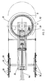
figure 3 montre une vue en plan de lafigure 1 , la position B en pointillé de la poulie correspondant à la course maximum du chariot mobile ; - la
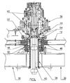
figure 4 représente une vue en coupe à échelle agrandie, de la liaison d'accouplement du réducteur avec la poulie. - Sur les
figures 1 à 4 , un câble porteur-tracteur 10 aérien d'un télésiège passe autour d'une poulie de renvoi 12 à axe vertical logée dans une gare ou station d'extrémité 14. Le câble 10 s'étend en boucle sans fin le long d'une voie montante, et d'une voie descendante, et les sièges, dont l'un 16 est représenté sur lafigure 2 , sont accrochés au câble 10 à intervalles réguliers par des pinces 18 de retenue fixes. - La station 14 illustrée à la
figure 1 , est une station aval motrice, dans laquelle la poulie de renvoi 12 horizontale est entraînée en rotation par un mécanisme motoréducteur 20 s'étendant perpendiculairement à la poulie 12, l'ensemble étant porté par un dispositif de support 22 avec un décalage en hauteur prédéterminé. - Le dispositif de support 22 est composé d'un socle 24 fixe en béton ancré au sol, et d'un châssis 26 métallique horizontal comprenant des profilés fixes 28 en l, et un chariot 30 monté à translation horizontale par l'intermédiaire d'organes de roulement 32.
- La poulie 12 et le mécanisme motoréducteur 20 sont montés sur l'une des extrémités du chariot 30. La course longitudinale du chariot 30 s'étend sur une longueur de l'ordre de 3 mètres entre les positions A et B de la
figure 3 , pour assurer la tension du câble 10. Un dispositif tendeur, formé par exemple par un vérin 66 ou un contrepoids, est associé au chariot de manière à agir dans la direction de la ligne. - Le mécanisme motoréducteur 20 comporte un moteur électrique 34 disposé sous la poulie 12, et un réducteur 36 de vitesse agencé au-dessus de la poulie 12, et en alignement coaxial avec le moteur 34. L'arbre de sortie vertical du moteur 34 est muni d'un volant 37 d'inertie, et traverse un fourreau 38 tubulaire assujetti au chariot 30, de manière à constituer l'arbre 40 à grande vitesse accouplé à l'entrée du réducteur 36.
- Le réducteur 36 mécanique est doté de plusieurs étages d'engrenages 42 démultiplicateurs, et d'un arbre de sortie 44 à petite vitesse pour l'entraînement en rotation de la poulie 12. Une paire de roulements 46 est intercalée coaxialement entre le fourreau 38 fixe et un alésage 48 cylindrique du moyeu 50 de la poulie 12. L'arbre de sortie 44 du réducteur 36 est creux, et est accouplé directement à un manchon 52 d'entraînement fixé au moyeu 50 par des vis et pions 54 d'assemblage. Le carter du réducteur 36 est supporté par une paire de bras de couple 55.
- Les deux arbres 40, 44 sont coaxiaux en s'étendant perpendiculairement par rapport à la poulie 12. Le montage modulaire en ligne d'arbres du mécanisme motoréducteur 20 permet d'obtenir une chaîne cinématique courte sans nécessiter des moyens de transmission intercalaires du type couple conique. La structure d'entraînement selon l'invention permet de réduire le temps de montage, ainsi que l'encombrement longitudinal de la station 14.
- Un train de galets 56 est monté sur un balancier 58 articulé à l'entrée de la station 14 autour d'un axe transversal 60 de manière à dévier le câble 10 vers le bas en direction de la poulie 12.
- Une roue dentée 62 de secours est rigidement fixée à la face inférieure de la poulie 12 pour coopérer avec un moteur de secours 64 solidaire du chariot 30. Le moteur de secours 64 peut un motoréducteur électrique entraîné par un groupe électrogène, ou un moteur hydraulique. La poulie de renvoi 12 peut ainsi être entraînée en rotation par le moteur de secours 64 en cas d'intervention sur le mécanisme motoréducteur 20.
- Le montage de la poulie de renvoi 12 sur le chariot 30 mobile, et l'utilisation d'éléments standards pour constituer le mécanisme motoréducteur 20, permettent d'obtenir une modularité des sous-ensembles de stations de télésièges.
- Dans le cas d'une station aval 14 selon la
figure 1 , la poulie 12 est une poulie motrice entraînée en rotation par le mécanisme motoréducteur 20. Le déplacement vers la droite du chariot 30 (flèche F,figure 3 ) entre les positions A et B, permet en plus d'assurer une tension du câble 10. - La poulie 12 peut également être transformée en simple poulie de tension, par exemple pour la station amont du télésiège. Dans ce cas, le moteur électrique 34 et le réducteur 36 ne sont pas montés. II suffit de supprimer la liaison d'accouplement du réducteur 36 et du moteur électrique 34 avec la poulie 12. En coulissant sous l'action du vérin 66 du dispositif tendeur agissant dans la direction de la ligne, le chariot 30 maintient le câble 10 en permanence sous tension constante.
- Selon une variante sans réducteur mécanique, le moteur peut être équipé d'un commutateur électronique de vitesse pour l'entraînement direct de la poulie à axe vertical.
Claims (10)
- Télésiège de transport à câble (10) aérien porteur-tracteur et à pinces fixes de retenue des sièges (16), comprenant dans une station (14) une poulie de renvoi (12) sur laquelle passe la câble (10), et des moyens de positionnement de la poulie (12) à axe vertical sur un chariot (30) monté sur un dispositif de support (22) pour une utilisation en poulie motrice entraînée par un mécanisme motoréducteur (20) et/ou en poulie de tension,
caractérisé en ce que le mécanisme motoréducteur (20) comporte une ligne d'arbres coaxiaux s'étendant perpendiculairement à la poulie de renvoi (12) selon une direction sensiblement verticale. - Télésiège selon la revendication 1, caractérisé en ce que le mécanisme motoréducteur (20) est composé d'un moteur électrique (34) et d'un réducteur (36) mécanique constituant deux modules indépendants disposés de part et d'autre de la poulie de renvoi (12)
- Télésiège selon la revendication 2, caractérisé en ce que le premier arbre de sortie (40) à grande vitesse du moteur (34) traverse un fourreau (38) tubulaire solidaire du chariot (30), et est entouré coaxialement par le deuxième arbre de sortie (44) creux à petite vitesse du réducteur (36).
- Télésiège selon la revendication 3, caractérisé en ce que le moyeu (50) de la poulie (12) tourne autour du fourreau (38) avec interposition de roulements (46), et comporte un manchon (52) d'entraînement relié au deuxième arbre (44) rotatif du réducteur (36).
- Télésiège selon la revendication 1 à 4, caractérisé en ce que le réducteur (36) mécanique à engrenages (42) de démultiplication est situé au-dessus de la poulie (12), et à l'opposé du moteur électrique (34) par rapport à la direction verticale.
- Télésiège selon la revendication 1, caractérisé en ce que le mécanisme motoréducteur (20) comprend un moteur équipé d'un commutateur électronique de vitesse pour l'entraînement direct de la poulie (12).
- Télésiège selon l'une des revendications 1 à 6, caractérisé en ce que la poulie (12) est dotée d'une roue dentée (62) susceptible de coopérer avec un moteur de secours (64) solidaire du chariot (30).
- Télésiège selon la revendication 1, caractérisé en ce que le dispositif de support (22) comprend un socle (24) supportant des profilés fixes (28) horizontaux le long desquels se déplace le chariot (30) par l'intermédiaire d'organes de roulement (32).
- Télésiège selon la revendication 8, caractérisé en ce que le chariot (30) de support de la poulie de renvoi (12) est associé à un dispositif tendeur (66) agissant dans la direction de la ligne pour la mise sous tension mécanique du câble (10).
- Télésiège selon la revendication 7, caractérisé en ce que le moteur de secours (64) est formé par un motoréducteur électrique entraîné par un groupe électrogène.
Applications Claiming Priority (2)
| Application Number | Priority Date | Filing Date | Title |
|---|---|---|---|
| FR0210924A FR2843928B1 (fr) | 2002-09-04 | 2002-09-04 | Dispositif d'entrainement d'une poulie de renvoi d'un telesiege mono cable a pinces fixes. |
| FR0210924 | 2002-09-04 |
Publications (2)
| Publication Number | Publication Date |
|---|---|
| EP1396408A1 EP1396408A1 (fr) | 2004-03-10 |
| EP1396408B1 true EP1396408B1 (fr) | 2009-03-25 |
Family
ID=31503097
Family Applications (1)
| Application Number | Title | Priority Date | Filing Date |
|---|---|---|---|
| EP03354068A Expired - Lifetime EP1396408B1 (fr) | 2002-09-04 | 2003-07-23 | Dispositif d'entraînement d'une poulie de renvoi d'un télésiège mono câble à pinces fixes |
Country Status (8)
| Country | Link |
|---|---|
| US (1) | US7036435B2 (fr) |
| EP (1) | EP1396408B1 (fr) |
| JP (1) | JP2004099027A (fr) |
| AT (1) | ATE426534T1 (fr) |
| CA (1) | CA2436761A1 (fr) |
| DE (1) | DE60326796D1 (fr) |
| ES (1) | ES2323633T3 (fr) |
| FR (1) | FR2843928B1 (fr) |
Families Citing this family (9)
| Publication number | Priority date | Publication date | Assignee | Title |
|---|---|---|---|---|
| KR20070119047A (ko) * | 2005-03-25 | 2007-12-18 | 인더스트리얼 오리가미, 엘엘씨. | 정밀 폴드 기술로 형성된 3차원 구조체 및 그 형성 방법 |
| DE602005017433D1 (de) * | 2005-06-01 | 2009-12-10 | Cesar Sousa Jaques Americo | Pneumatisches oder hydraulisches teleskopsystem für türme und stationen von sesselliften, gondelbahnen und andere |
| DE202007003043U1 (de) * | 2007-02-28 | 2007-04-26 | Lohmann & Stolterfoht Gmbh | Seilbahngetriebe mit mehreren Planetenstufen |
| JP5455736B2 (ja) * | 2010-03-25 | 2014-03-26 | 日本ケーブル株式会社 | 索道の原動機 |
| FR2958988B1 (fr) * | 2010-04-16 | 2012-05-18 | Pomagalski Sa | Procede et installation de mise sous tension d'un cable |
| IT1403260B1 (it) * | 2010-12-15 | 2013-10-17 | Rolic Invest Sarl | Impianto di trasporto a fune con almeno una fune traente |
| JP6366314B2 (ja) * | 2014-03-24 | 2018-08-01 | 日本ケーブル株式会社 | 索条式輸送設備の原動装置 |
| JP6562498B2 (ja) * | 2015-02-26 | 2019-08-21 | 日本ケーブル株式会社 | 索道における原動滑車の軸構造 |
| CN109398708A (zh) * | 2018-12-19 | 2019-03-01 | 攀枝花学院 | 一种无人机提升装置 |
Family Cites Families (11)
| Publication number | Priority date | Publication date | Assignee | Title |
|---|---|---|---|---|
| US2285636A (en) * | 1940-12-23 | 1942-06-09 | Eugene Wallace | Ski tow mechanism |
| AT337248B (de) * | 1975-02-20 | 1977-06-27 | Wopfner Franz | Antriebsanordnung fur seilbahnen, schlepp- und sessellifte od.dgl. |
| FR2255200B1 (fr) * | 1973-12-20 | 1976-07-23 | Pomagalski Sa | |
| US4003314A (en) * | 1975-04-25 | 1977-01-18 | Pearson William F | Ski lift monitoring |
| FR2320852A1 (fr) * | 1975-08-14 | 1977-03-11 | Pomagalski Sa | Telesiege a systeme automatique de controle de vitesse |
| US4100822A (en) * | 1976-04-19 | 1978-07-18 | Allan Rosman | Drive system for a moving mechanism |
| SE449971B (sv) * | 1985-08-15 | 1987-06-01 | Liftbyggarna Ab | Linspenningsanordning for lift- eller linbaneanleggningar |
| AT385247B (de) * | 1986-06-03 | 1988-03-10 | Doppelmayr & Sohn | Mehrfachfoerderseil-umlaufbahn, insbesondere doppelfoerderseil-umlaufbahn |
| AT388345B (de) * | 1987-02-11 | 1989-06-12 | Erste Oesterr Zahnraeder | Antriebsanordnung fuer die seilscheibe von seilfoerderanlagen |
| FR2641510B1 (fr) * | 1989-01-09 | 1991-03-29 | Von Roll Transportsysteme | Installation de transport par cable a tension controlee |
| FR2661147B1 (fr) * | 1990-04-24 | 1992-07-24 | Pomagalski Sa | Station d'extremite de tension d'un teleporteur. |
-
2002
- 2002-09-04 FR FR0210924A patent/FR2843928B1/fr not_active Expired - Fee Related
-
2003
- 2003-07-23 ES ES03354068T patent/ES2323633T3/es not_active Expired - Lifetime
- 2003-07-23 EP EP03354068A patent/EP1396408B1/fr not_active Expired - Lifetime
- 2003-07-23 DE DE60326796T patent/DE60326796D1/de not_active Expired - Lifetime
- 2003-07-23 AT AT03354068T patent/ATE426534T1/de active
- 2003-07-29 US US10/628,399 patent/US7036435B2/en not_active Expired - Lifetime
- 2003-08-07 CA CA002436761A patent/CA2436761A1/fr not_active Abandoned
- 2003-09-01 JP JP2003308854A patent/JP2004099027A/ja active Pending
Also Published As
| Publication number | Publication date |
|---|---|
| US20050051049A1 (en) | 2005-03-10 |
| US7036435B2 (en) | 2006-05-02 |
| JP2004099027A (ja) | 2004-04-02 |
| ES2323633T3 (es) | 2009-07-22 |
| FR2843928A1 (fr) | 2004-03-05 |
| EP1396408A1 (fr) | 2004-03-10 |
| FR2843928B1 (fr) | 2004-12-10 |
| DE60326796D1 (de) | 2009-05-07 |
| CA2436761A1 (fr) | 2004-03-04 |
| ATE426534T1 (de) | 2009-04-15 |
Similar Documents
| Publication | Publication Date | Title |
|---|---|---|
| EP0006097B1 (fr) | Transporteur de câbles | |
| CH656357A5 (fr) | Vehicule motorise suspendu. | |
| FR2725708A1 (fr) | Chariot destine a etre suspendu et a se deplacer sur un rail | |
| EP1396408A1 (fr) | Dispositif d'entraínement d'une poulie de renvoi d'un télésiège mono câble à pinces fixes | |
| FR2552062A1 (fr) | Appareil de transport notamment pour le transport de personnes entre deux niveaux espaces | |
| EP0454596B1 (fr) | Station d'extrémité de tension d'un téléporteur | |
| FR2792921A1 (fr) | Repartiteur de produits pour installation de convoyage | |
| EP0330548B1 (fr) | Dispositif d'équilibrage des forces, notamment de pesanteur, agissant sur un bras de robot ou analogue | |
| FR2591160A1 (fr) | Appareil pour le chargement ou le dechargement de cargaisons | |
| CH619656A5 (en) | Handling device comprising an overhead track | |
| FR2604138A1 (fr) | Dispositif de maintien en ligne au droit d'un pylone de cables aeriens entraines a defilement, et installation de transport a cables aeriens comportant un tel dispositif | |
| EP2691278B1 (fr) | Téléporteur aérien à va-et-vient et à tronçons multiples | |
| FR2635762A1 (fr) | Element courbe pour chemin de transfert | |
| FR2767707A1 (fr) | Machine de musculation | |
| FR2801267A1 (fr) | Remontee mecanique comportant un cable sans fin et balancier support/compression pour une telle remontee mecanique | |
| EP0570262B1 (fr) | Dispositif de convoyage de supports de charges | |
| FR2668439A1 (fr) | Dispositif de transport de charges dans une cage d'escalier par exemple. | |
| FR2652127A1 (fr) | Moteur utilisant et transformant en mouvement rotatif une poussee lineaire statique. | |
| FR2659261A1 (fr) | Actionneur reproducteur de deplacement et manipulateur equipe d'un tel dispositif. | |
| FR2830611A1 (fr) | Dispositif pour le deplacement d'une cible pour la pratique du tir | |
| FR2897049A1 (fr) | Table elevatrice a pietements articules. | |
| CH93952A (fr) | Transporteur aérien. | |
| FR2622329A1 (fr) | Centrifugeuse notamment pour l'etude des effets physiopathologiques des accelerations | |
| FR2499818A1 (fr) | Machine notamment pour epamprer la vigne | |
| FR2774053A1 (fr) | Mecanisme d'entrainemement d'une installation de transport a cables ayant une poulie motrice a double adherence |
Legal Events
| Date | Code | Title | Description |
|---|---|---|---|
| PUAI | Public reference made under article 153(3) epc to a published international application that has entered the european phase |
Free format text: ORIGINAL CODE: 0009012 |
|
| AK | Designated contracting states |
Kind code of ref document: A1 Designated state(s): AT BE BG CH CY CZ DE DK EE ES FI FR GB GR HU IE IT LI LU MC NL PT RO SE SI SK TR |
|
| AX | Request for extension of the european patent |
Extension state: AL LT LV MK |
|
| 17P | Request for examination filed |
Effective date: 20040903 |
|
| AKX | Designation fees paid |
Designated state(s): AT BE BG CH CY CZ DE DK EE ES FI FR GB GR HU IE IT LI LU MC NL PT RO SE SI SK TR |
|
| GRAC | Information related to communication of intention to grant a patent modified |
Free format text: ORIGINAL CODE: EPIDOSCIGR1 |
|
| GRAP | Despatch of communication of intention to grant a patent |
Free format text: ORIGINAL CODE: EPIDOSNIGR1 |
|
| RAP1 | Party data changed (applicant data changed or rights of an application transferred) |
Owner name: POMAGALSKI |
|
| GRAS | Grant fee paid |
Free format text: ORIGINAL CODE: EPIDOSNIGR3 |
|
| GRAA | (expected) grant |
Free format text: ORIGINAL CODE: 0009210 |
|
| AK | Designated contracting states |
Kind code of ref document: B1 Designated state(s): AT BE BG CH CY CZ DE DK EE ES FI FR GB GR HU IE IT LI LU MC NL PT RO SE SI SK TR |
|
| REG | Reference to a national code |
Ref country code: GB Ref legal event code: FG4D Free format text: NOT ENGLISH |
|
| REG | Reference to a national code |
Ref country code: CH Ref legal event code: EP |
|
| REG | Reference to a national code |
Ref country code: IE Ref legal event code: FG4D Free format text: LANGUAGE OF EP DOCUMENT: FRENCH |
|
| REF | Corresponds to: |
Ref document number: 60326796 Country of ref document: DE Date of ref document: 20090507 Kind code of ref document: P |
|
| REG | Reference to a national code |
Ref country code: CH Ref legal event code: NV Representative=s name: CABINET ROLAND NITHARDT CONSEILS EN PROPRIETE INDU |
|
| REG | Reference to a national code |
Ref country code: ES Ref legal event code: FG2A Ref document number: 2323633 Country of ref document: ES Kind code of ref document: T3 |
|
| PG25 | Lapsed in a contracting state [announced via postgrant information from national office to epo] |
Ref country code: FI Free format text: LAPSE BECAUSE OF FAILURE TO SUBMIT A TRANSLATION OF THE DESCRIPTION OR TO PAY THE FEE WITHIN THE PRESCRIBED TIME-LIMIT Effective date: 20090325 Ref country code: SI Free format text: LAPSE BECAUSE OF FAILURE TO SUBMIT A TRANSLATION OF THE DESCRIPTION OR TO PAY THE FEE WITHIN THE PRESCRIBED TIME-LIMIT Effective date: 20090325 |
|
| PG25 | Lapsed in a contracting state [announced via postgrant information from national office to epo] |
Ref country code: SE Free format text: LAPSE BECAUSE OF FAILURE TO SUBMIT A TRANSLATION OF THE DESCRIPTION OR TO PAY THE FEE WITHIN THE PRESCRIBED TIME-LIMIT Effective date: 20090625 |
|
| PGFP | Annual fee paid to national office [announced via postgrant information from national office to epo] |
Ref country code: TR Payment date: 20090626 Year of fee payment: 7 |
|
| NLV1 | Nl: lapsed or annulled due to failure to fulfill the requirements of art. 29p and 29m of the patents act | ||
| REG | Reference to a national code |
Ref country code: IE Ref legal event code: FD4D |
|
| PG25 | Lapsed in a contracting state [announced via postgrant information from national office to epo] |
Ref country code: EE Free format text: LAPSE BECAUSE OF FAILURE TO SUBMIT A TRANSLATION OF THE DESCRIPTION OR TO PAY THE FEE WITHIN THE PRESCRIBED TIME-LIMIT Effective date: 20090325 Ref country code: PT Free format text: LAPSE BECAUSE OF FAILURE TO SUBMIT A TRANSLATION OF THE DESCRIPTION OR TO PAY THE FEE WITHIN THE PRESCRIBED TIME-LIMIT Effective date: 20090901 |
|
| PGFP | Annual fee paid to national office [announced via postgrant information from national office to epo] |
Ref country code: ES Payment date: 20090812 Year of fee payment: 7 |
|
| PG25 | Lapsed in a contracting state [announced via postgrant information from national office to epo] |
Ref country code: RO Free format text: LAPSE BECAUSE OF FAILURE TO SUBMIT A TRANSLATION OF THE DESCRIPTION OR TO PAY THE FEE WITHIN THE PRESCRIBED TIME-LIMIT Effective date: 20090325 Ref country code: SK Free format text: LAPSE BECAUSE OF FAILURE TO SUBMIT A TRANSLATION OF THE DESCRIPTION OR TO PAY THE FEE WITHIN THE PRESCRIBED TIME-LIMIT Effective date: 20090325 Ref country code: NL Free format text: LAPSE BECAUSE OF FAILURE TO SUBMIT A TRANSLATION OF THE DESCRIPTION OR TO PAY THE FEE WITHIN THE PRESCRIBED TIME-LIMIT Effective date: 20090325 |
|
| PGFP | Annual fee paid to national office [announced via postgrant information from national office to epo] |
Ref country code: CZ Payment date: 20090708 Year of fee payment: 7 |
|
| PG25 | Lapsed in a contracting state [announced via postgrant information from national office to epo] |
Ref country code: DK Free format text: LAPSE BECAUSE OF FAILURE TO SUBMIT A TRANSLATION OF THE DESCRIPTION OR TO PAY THE FEE WITHIN THE PRESCRIBED TIME-LIMIT Effective date: 20090325 Ref country code: IE Free format text: LAPSE BECAUSE OF FAILURE TO SUBMIT A TRANSLATION OF THE DESCRIPTION OR TO PAY THE FEE WITHIN THE PRESCRIBED TIME-LIMIT Effective date: 20090325 Ref country code: BG Free format text: LAPSE BECAUSE OF FAILURE TO SUBMIT A TRANSLATION OF THE DESCRIPTION OR TO PAY THE FEE WITHIN THE PRESCRIBED TIME-LIMIT Effective date: 20090625 |
|
| PLBE | No opposition filed within time limit |
Free format text: ORIGINAL CODE: 0009261 |
|
| STAA | Information on the status of an ep patent application or granted ep patent |
Free format text: STATUS: NO OPPOSITION FILED WITHIN TIME LIMIT |
|
| BERE | Be: lapsed |
Owner name: POMAGALSKI Effective date: 20090731 |
|
| PG25 | Lapsed in a contracting state [announced via postgrant information from national office to epo] |
Ref country code: MC Free format text: LAPSE BECAUSE OF NON-PAYMENT OF DUE FEES Effective date: 20090731 |
|
| 26N | No opposition filed |
Effective date: 20091229 |
|
| GBPC | Gb: european patent ceased through non-payment of renewal fee |
Effective date: 20090723 |
|
| PG25 | Lapsed in a contracting state [announced via postgrant information from national office to epo] |
Ref country code: GB Free format text: LAPSE BECAUSE OF NON-PAYMENT OF DUE FEES Effective date: 20090723 |
|
| PG25 | Lapsed in a contracting state [announced via postgrant information from national office to epo] |
Ref country code: BE Free format text: LAPSE BECAUSE OF NON-PAYMENT OF DUE FEES Effective date: 20090731 |
|
| PG25 | Lapsed in a contracting state [announced via postgrant information from national office to epo] |
Ref country code: GR Free format text: LAPSE BECAUSE OF FAILURE TO SUBMIT A TRANSLATION OF THE DESCRIPTION OR TO PAY THE FEE WITHIN THE PRESCRIBED TIME-LIMIT Effective date: 20090626 |
|
| PG25 | Lapsed in a contracting state [announced via postgrant information from national office to epo] |
Ref country code: LU Free format text: LAPSE BECAUSE OF NON-PAYMENT OF DUE FEES Effective date: 20090723 |
|
| PG25 | Lapsed in a contracting state [announced via postgrant information from national office to epo] |
Ref country code: CZ Free format text: LAPSE BECAUSE OF NON-PAYMENT OF DUE FEES Effective date: 20100723 |
|
| PG25 | Lapsed in a contracting state [announced via postgrant information from national office to epo] |
Ref country code: HU Free format text: LAPSE BECAUSE OF FAILURE TO SUBMIT A TRANSLATION OF THE DESCRIPTION OR TO PAY THE FEE WITHIN THE PRESCRIBED TIME-LIMIT Effective date: 20090926 |
|
| REG | Reference to a national code |
Ref country code: ES Ref legal event code: FD2A Effective date: 20110818 |
|
| PG25 | Lapsed in a contracting state [announced via postgrant information from national office to epo] |
Ref country code: CY Free format text: LAPSE BECAUSE OF FAILURE TO SUBMIT A TRANSLATION OF THE DESCRIPTION OR TO PAY THE FEE WITHIN THE PRESCRIBED TIME-LIMIT Effective date: 20090325 |
|
| PG25 | Lapsed in a contracting state [announced via postgrant information from national office to epo] |
Ref country code: ES Free format text: LAPSE BECAUSE OF NON-PAYMENT OF DUE FEES Effective date: 20100724 |
|
| PG25 | Lapsed in a contracting state [announced via postgrant information from national office to epo] |
Ref country code: TR Free format text: LAPSE BECAUSE OF NON-PAYMENT OF DUE FEES Effective date: 20100723 |
|
| REG | Reference to a national code |
Ref country code: FR Ref legal event code: PLFP Year of fee payment: 14 |
|
| REG | Reference to a national code |
Ref country code: FR Ref legal event code: PLFP Year of fee payment: 15 |
|
| REG | Reference to a national code |
Ref country code: FR Ref legal event code: PLFP Year of fee payment: 16 |
|
| PGFP | Annual fee paid to national office [announced via postgrant information from national office to epo] |
Ref country code: AT Payment date: 20210721 Year of fee payment: 19 Ref country code: FR Payment date: 20210726 Year of fee payment: 19 Ref country code: IT Payment date: 20210707 Year of fee payment: 19 |
|
| PGFP | Annual fee paid to national office [announced via postgrant information from national office to epo] |
Ref country code: CH Payment date: 20210722 Year of fee payment: 19 Ref country code: DE Payment date: 20210729 Year of fee payment: 19 |
|
| REG | Reference to a national code |
Ref country code: DE Ref legal event code: R119 Ref document number: 60326796 Country of ref document: DE |
|
| REG | Reference to a national code |
Ref country code: CH Ref legal event code: PL |
|
| REG | Reference to a national code |
Ref country code: AT Ref legal event code: MM01 Ref document number: 426534 Country of ref document: AT Kind code of ref document: T Effective date: 20220723 |
|
| PG25 | Lapsed in a contracting state [announced via postgrant information from national office to epo] |
Ref country code: LI Free format text: LAPSE BECAUSE OF NON-PAYMENT OF DUE FEES Effective date: 20220731 Ref country code: FR Free format text: LAPSE BECAUSE OF NON-PAYMENT OF DUE FEES Effective date: 20220731 Ref country code: CH Free format text: LAPSE BECAUSE OF NON-PAYMENT OF DUE FEES Effective date: 20220731 Ref country code: AT Free format text: LAPSE BECAUSE OF NON-PAYMENT OF DUE FEES Effective date: 20220723 |
|
| PG25 | Lapsed in a contracting state [announced via postgrant information from national office to epo] |
Ref country code: DE Free format text: LAPSE BECAUSE OF NON-PAYMENT OF DUE FEES Effective date: 20230201 |
|
| PG25 | Lapsed in a contracting state [announced via postgrant information from national office to epo] |
Ref country code: IT Free format text: LAPSE BECAUSE OF NON-PAYMENT OF DUE FEES Effective date: 20220723 |