EP1394885A1 - Brennstoffzelle - Google Patents
Brennstoffzelle Download PDFInfo
- Publication number
- EP1394885A1 EP1394885A1 EP03255236A EP03255236A EP1394885A1 EP 1394885 A1 EP1394885 A1 EP 1394885A1 EP 03255236 A EP03255236 A EP 03255236A EP 03255236 A EP03255236 A EP 03255236A EP 1394885 A1 EP1394885 A1 EP 1394885A1
- Authority
- EP
- European Patent Office
- Prior art keywords
- layer
- single cell
- fuel cell
- comprised
- anode
- Prior art date
- Legal status (The legal status is an assumption and is not a legal conclusion. Google has not performed a legal analysis and makes no representation as to the accuracy of the status listed.)
- Granted
Links
Images


Classifications
-
- H—ELECTRICITY
- H01—ELECTRIC ELEMENTS
- H01M—PROCESSES OR MEANS, e.g. BATTERIES, FOR THE DIRECT CONVERSION OF CHEMICAL ENERGY INTO ELECTRICAL ENERGY
- H01M8/00—Fuel cells; Manufacture thereof
- H01M8/10—Fuel cells with solid electrolytes
- H01M8/12—Fuel cells with solid electrolytes operating at high temperature, e.g. with stabilised ZrO2 electrolyte
- H01M8/1213—Fuel cells with solid electrolytes operating at high temperature, e.g. with stabilised ZrO2 electrolyte characterised by the electrode/electrolyte combination or the supporting material
-
- H—ELECTRICITY
- H01—ELECTRIC ELEMENTS
- H01M—PROCESSES OR MEANS, e.g. BATTERIES, FOR THE DIRECT CONVERSION OF CHEMICAL ENERGY INTO ELECTRICAL ENERGY
- H01M8/00—Fuel cells; Manufacture thereof
- H01M8/04—Auxiliary arrangements, e.g. for control of pressure or for circulation of fluids
- H01M8/04082—Arrangements for control of reactant parameters, e.g. pressure or concentration
- H01M8/04089—Arrangements for control of reactant parameters, e.g. pressure or concentration of gaseous reactants
-
- H—ELECTRICITY
- H01—ELECTRIC ELEMENTS
- H01M—PROCESSES OR MEANS, e.g. BATTERIES, FOR THE DIRECT CONVERSION OF CHEMICAL ENERGY INTO ELECTRICAL ENERGY
- H01M8/00—Fuel cells; Manufacture thereof
- H01M8/24—Grouping of fuel cells, e.g. stacking of fuel cells
- H01M8/241—Grouping of fuel cells, e.g. stacking of fuel cells with solid or matrix-supported electrolytes
- H01M8/2425—High-temperature cells with solid electrolytes
- H01M8/243—Grouping of unit cells of tubular or cylindrical configuration
-
- H—ELECTRICITY
- H01—ELECTRIC ELEMENTS
- H01M—PROCESSES OR MEANS, e.g. BATTERIES, FOR THE DIRECT CONVERSION OF CHEMICAL ENERGY INTO ELECTRICAL ENERGY
- H01M8/00—Fuel cells; Manufacture thereof
- H01M8/24—Grouping of fuel cells, e.g. stacking of fuel cells
- H01M8/241—Grouping of fuel cells, e.g. stacking of fuel cells with solid or matrix-supported electrolytes
- H01M8/2425—High-temperature cells with solid electrolytes
- H01M8/2432—Grouping of unit cells of planar configuration
-
- H—ELECTRICITY
- H01—ELECTRIC ELEMENTS
- H01M—PROCESSES OR MEANS, e.g. BATTERIES, FOR THE DIRECT CONVERSION OF CHEMICAL ENERGY INTO ELECTRICAL ENERGY
- H01M8/00—Fuel cells; Manufacture thereof
- H01M8/10—Fuel cells with solid electrolytes
- H01M8/12—Fuel cells with solid electrolytes operating at high temperature, e.g. with stabilised ZrO2 electrolyte
- H01M8/124—Fuel cells with solid electrolytes operating at high temperature, e.g. with stabilised ZrO2 electrolyte characterised by the process of manufacturing or by the material of the electrolyte
-
- Y—GENERAL TAGGING OF NEW TECHNOLOGICAL DEVELOPMENTS; GENERAL TAGGING OF CROSS-SECTIONAL TECHNOLOGIES SPANNING OVER SEVERAL SECTIONS OF THE IPC; TECHNICAL SUBJECTS COVERED BY FORMER USPC CROSS-REFERENCE ART COLLECTIONS [XRACs] AND DIGESTS
- Y02—TECHNOLOGIES OR APPLICATIONS FOR MITIGATION OR ADAPTATION AGAINST CLIMATE CHANGE
- Y02E—REDUCTION OF GREENHOUSE GAS [GHG] EMISSIONS, RELATED TO ENERGY GENERATION, TRANSMISSION OR DISTRIBUTION
- Y02E60/00—Enabling technologies; Technologies with a potential or indirect contribution to GHG emissions mitigation
- Y02E60/30—Hydrogen technology
- Y02E60/50—Fuel cells
-
- Y—GENERAL TAGGING OF NEW TECHNOLOGICAL DEVELOPMENTS; GENERAL TAGGING OF CROSS-SECTIONAL TECHNOLOGIES SPANNING OVER SEVERAL SECTIONS OF THE IPC; TECHNICAL SUBJECTS COVERED BY FORMER USPC CROSS-REFERENCE ART COLLECTIONS [XRACs] AND DIGESTS
- Y02—TECHNOLOGIES OR APPLICATIONS FOR MITIGATION OR ADAPTATION AGAINST CLIMATE CHANGE
- Y02P—CLIMATE CHANGE MITIGATION TECHNOLOGIES IN THE PRODUCTION OR PROCESSING OF GOODS
- Y02P70/00—Climate change mitigation technologies in the production process for final industrial or consumer products
- Y02P70/50—Manufacturing or production processes characterised by the final manufactured product
Definitions
- the present invention relates to a fuel cell, more particularly relates to a fuel cell in which a cathode layer and anode layer sandwiching a solid electrolyte layer are supplied with a mixed gas of a fuel gas and air mixed together.
- a cylindrical fuel cell for use as a fuel cell is proposed in Japanese Unexamined Patent Publication (Kokai) No. 7-282823.
- This cylindrical fuel cell as shown in FIG. 17, is comprised of a cylindrical base member 100 comprised of a porous ceramic, a porous anode layer (air electrode) 102 formed at the outer circumference of the cylindrical base member 100, a solid electrolyte 104 comprised of yttria-containing stabilized zirconia formed at the outer circumferential surface of the anode layer 102, and a cathode layer (fuel electrode) 106 formed at the outer circumferential surface of the solid electrolyte 104 - all formed concentrically.
- this cylindrical fuel cell has an interconnector 108 passing through the solid electrolyte 104 to be connected with the anode layer 102 and not in contact with the cathode layer 106. The surface of the cell is exposed.
- this cylindrical fuel cell by passing air through the inside the cylindrical base member in an atmosphere of 900 to 1000°C and passing methane or hydrogen or another fuel gas along the outer circumferential surface of the cathode layer 106, it is possible to generate an electromotive force by the electrochemical reaction between the oxygen in the air and the fuel ingredients in the fuel gas.
- the cylindrical fuel cell shown in FIG. 17 it is possible to reduce the size compared with a planar fuel cell and possible to easily separate the air flowing through the cylindrical base member 100 and the fuel gas flowing along the outer circumferential surface of the cathode layer 106.
- the cell has to be made larger in diameter and the fuel cell becomes larger in size.
- An object of the present invention is to provide a fuel cell not increased in size even if increasing the contact area of the anode layer and cathode layer with the air or fuel gas.
- the inventors engaged in studies to achieve this object and as a result found that when reliable separation of the air and fuel gas is necessary, the size of the fuel cell is proportional to the contact area of the anode layer and cathode layer with the air or fuel gas.
- Science , vol. 288 (2000), p. 2031-2033 reports that if a fuel cell formed with a cathode layer and anode layer at the two surfaces of a solid electrolyte layer is placed in a mixed fuel gas of methane gas and oxygen, the fuel cell will generate an electromotive force.
- the inventors concluded that it was not necessary to separate the flow of air at the anode layer side and the flow of fuel at the cathode layer side and that it was possible to freely change the shape of the fuel cell formed with the cathode layer and anode layer at the two surfaces of the solid electrolyte layer. As a result, they discovered a fuel cell enabling the contact area with the mixed gas to be increased to the maximum and thereby perfected the present invention.
- a fuel cell comprised of a solid electrolyte layer sandwiched by a cathode layer and an anode layer to which a mixed gas of a fuel gas and air mixed together is supplied, wherein the fuel cell is formed into a spiral member comprised of a single cell layer comprised of the cathode layer, solid electrolyte layer, and anode layer stacked together or a multilayer member of a plurality of the single cell layers stacked together rolled up spirally, the cathode layer and anode layer forming facing surfaces of each upper stratum and lower stratum of the single cell layer or multilayer member adjoining each other in a diametrical direction of the spiral member are arranged through an electrical insulator, and the cathode layer and anode layer or the electrical insulator are or is formed with a gas passage enabling passage of the mixed gas.
- a fuel cell comprised of a solid electrolyte layer sandwiched by a cathode layer and an anode layer to which a mixed gas of a fuel gas and air mixed together is supplied, wherein the fuel cell is formed into a spiral member comprised of a single cell layer comprised of the cathode layer, solid electrolyte layer, and anode layer stacked together or a multilayer member of a plurality of the single cell layers stacked together rolled up spirally, facing surfaces of each upper stratum and lower stratum of the single cell layer or multilayer member adjoining each other in a diametrical direction of the spiral member are both formed by cathode layers or by anode layers, and the cathode layer and anode layer or facing surfaces of each upper stratum and lower stratum of the single cell layer or multilayer member have a gas passage enabling passage of the mixed gas formed between them.
- a fuel cell comprised of a solid electrolyte layer sandwiched by a cathode layer and an anode layer to which a mixed gas of a fuel gas and air mixed together is supplied, wherein the fuel cell is formed into a folded member comprised of a single cell layer comprised of the cathode layer, solid electrolyte layer, and anode layer stacked together or a multilayer member of a plurality of the single cell layers stacked together folded back and forth, facing surfaces of the adjoining strata of the single cell layer or multilayer member of the folded member are both formed by cathode layers or by anode layers, and the cathode layer and anode layer or facing surfaces of adjoining strata of the single cell layer or multilayer member have a gas passage enabling passage of the mixed gas formed between them.
- the fuel cell according to the present invention is comprised of a single cell layer of a cathode layer, solid electrolyte layer, and anode layer stacked together or of a multilayer member comprised of a plurality of such single cell layers rolled up spirally into a spiral member or folded back and forth into a folded member.
- the cathode layer and anode layer of the single cell layer or multilayer member forming the spiral member or folded member or the facing surfaces of adjoining strata of the single cell layer or multilayer member have a gas passage enabling passage of a mixed gas of air and a fuel gas mixed together formed between them. This fuel cell does not require separation of the air and fuel since a mixed gas of air and the fuel gas is supplied.
- the contact area of the anode layer and cathode layer of the single cell layer or multilayer member with the mixed gas can be easily enlarged.
- the contact area of the anode layer and cathode layer of the single cell layer or multilayer member with the mixed gas since the single cell layer or multilayer member is rolled up spirally into a spiral member or folded back and forth into a folded member, the size does not rapidly increase and an increase in cell size can be prevented.
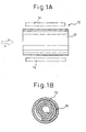
- FIGS. 1A and 1B An example of a fuel cell according to the present invention is shown in FIGS. 1A and 1B.
- FIG. 1A is a side view of a fuel cell 10
- FIG. 1B is a lateral sectional view of a fuel cell 10.
- the fuel cell 10 shown in FIGS. 1A and 1B is comprised of a ceramic or other cylindrical hollow container 12 having heat resistance, to be heated by a heater 14, in which a spiral member 16 is housed. This spiral member 16, as shown in the partial sectional view of FIG.
- a single cell layer 18 is comprised of a single cell layer 18, comprised of a solid electrolyte layer 18a, a cathode layer 18b, and an anode layer 18c stacked together so that the solid electrolyte layer 18a is sandwiched between the cathode layer 18b and anode layer 18c, spirally rolled up sandwiching an electrical insulator 20.
- This solid electrolyte layer 18a is an oxygen ion dielectric formed by zirconia oxide partially stabilized by yttrium (Y), scandium (Sc), or another element of Group III of the Periodic Table or cerium oxide doped with samarium (Sm), gadmium (Gd), etc.
- the cathode layer 18b is formed from a manganese, gallium, or cobalt oxide compound of lanthanum to which strontium (Sr) or another element of Group III of the Periodic Table is added, while the anode layer 18c is formed by a nickel-cermet or platinum carrier to which a solid electrolyte forming the solid electrolyte layer 18a is added in an amount of 10 to 30 wt%.
- the cathode layer 18b and anode layer 18c formed in this way are porous layers having open porosities of at least 20%, preferably 30 to 70%, particularly preferably 40 to 50%. Further, since the cathode layer 18b and anode layer 18c forming the single cell layer 18 are porous layers, the electrical insulator 20 can be made a compact layer.
- the spiral member 16 forming the multilayer fuel cell 10 shown in FIGS. 1A and 1B and FIG. 2 can be produced by the following procedure. First, a green sheet for forming the solid electrolyte layer 18a is sandwiched between a green sheet for forming the cathode layer 18b and a green sheet for forming the anode layer 18c to form a single cell layer green sheet for forming the single cell layer 18. Next, the single cell layer green sheet is stacked with a green sheet comprised of alumina etc. for forming an electrical insulator 20. This multilayer green sheet is then rolled up from one end to the other end to form a rolled member. Next, the rolled member can be fired under conditions of an atmosphere where a compact solid electrolyte layer 18a and electrical insulator 20 are formed so as to obtain a spiral member 16 shown in FIG. 1B and FIG. 2.
- the obtained spiral member 16, as shown in FIG. 1B, is housed in a hollow container 12.
- the spiral member 16 housed in this hollow container 12 is heated to a predetermined temperature by a heater arranged so as to surround the hollow container 12 while being supplied with a mixed gas of air and fuel gas mixed together from one end of the hollow container 12.
- the supplied mixed gas passes through the porous cathode layer 18b and anode layer 18c forming the single cell layer 18 and is exhausted from the other end of the hollow container 12.
- the oxygen ions obtained at the cathode layer 18b are conducted to the solid electrolyte layer 18a where they are electrochemically reacted with the fuel gas of the anode layer 18c, whereby electromotive force can be taken out from the cathode layer 18b and anode layer 18c.
- the electromotive force is preferably taken out from the cathode layer 18b and anode layer 18c of the part of the single cell layer 18 forming the topmost stratum of the spiral member 16.
- the reaction gas obtained at the anode layer 18c by the reaction of the oxygen ions conducted through the solid electrolyte layer 18a and fuel gas is exhausted from the other end of the hollow container 12 together with the mixed gas.
- the spiral member 16 shown in FIG. 2 is comprised of strata of the electrical insulator 20 between which one stratum of the single cell layer 18 comprised of the solid electrolyte layer 18a, cathode layer 18b, and anode layer 18c stacked together is sandwiched.
- strata of the electrical insulator 20 may have a multilayer member comprised of two single cell layers 18, 18 stacked together sandwiched between them.
- an anode layer 18c forming one of the single cell layers 18, 18 forming the multilayer member and the cathode layer 18b forming the other single cell layer are made to contact each other in the stacking.
- the electrical insulator 20 is formed as a compact layer, but it is also possible to form the electrical insulator 20 as a porous layer and form the solid electrolyte layer 18a, cathode layer 18b, and anode layer 18c into compact layers.
- the electrical insulator 20 instead of the electrical insulator 20, as shown in FIG. 4, it is also possible to provide a plurality of spacer members 30, 30... between adjoining strata of the single cell layer 18 to form a mixed gas passage.
- the spacer members 30 shown in FIG. 4 are comprised of alumina ceramic or other electrical insulators.
- the layers forming the facing surfaces of strata of the single cell layer are the anode layer 18c and cathode layer 18b, so it is necessary to prevent electrical short-circuits between the two layers.
- the spacer members 30, 30... may be shaped as rods extending in the longitudinal direction of the spiral member 16 or as points.
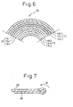
- the spiral member 16 shown in FIG. 2 and FIG. 3 requires the electrical insulator 20 or the spacer members 30 comprised of electrical insulators for preventing electrical short-circuits between strata of the single cell layer 18, but in the spiral member 16 shown in FIG. 5, as shown in the partial sectional view of FIG. 6, the electrical insulator 20 can be made unnecessary. This is because the spiral member 16 shown in FIG. 5 and FIG. 6 has an upper stratum of the single cell layer 18 and a lower stratum of the single cell layer 18 adjoining each other in the diametrical direction contacting each other by strata of the cathode layers 18b or by strata of the anode layers 18c. In the spiral member 16 shown in FIG. 5 and FIG.
- the components it is possible to make the components the same as the solid electrolyte layer 18a, cathode 18b, and anode layer 18c forming the single cell layer 18 shown in FIG. 2 and FIG. 3, but at least the cathode layer 18b and the anode layer 18c are made porous layers enabling passage of the mixed gas.
- each porous layer one with an open porosity of at least 20%, preferably 30 to 70%, particularly 40 to 50%, is preferred.
- the spiral member 16, as shown in FIG. 5, has the two ends of the single cell layer 18 positioned at the topmost surface of the spiral member 16, so it is possible to facilitate the connection with the lead wires for taking out the electromotive force.
- a green sheet for forming the solid electrolyte layer 18a is sandwiched between a green sheet for forming the cathode layer 18b and a green sheet for forming the anode layer 18c to form a single cell layer green sheet for forming the single cell layer 18.
- the single cell layer green sheet 28 is folded into two at its center so that surfaces of the green sheet for forming the cathode layer 18b or the green sheet for forming the anode layer 18c face each other.
- this is rolled up from the folded end in the direction of the arrow B to obtain a spiral member comprised of green sheets.
- the spiral member comprised of the green sheets can be fired at a predetermined temperature so as to form the spiral member 16 shown in FIG. 5 and FIG. 6. Further, it is also possible to form the solid electrolyte layer 18a of the single cell layer 18 as a porous layer and, as shown in FIG. 3, possible to fold a multilayer member comprised of a plurality of stacked single cell layers 18.
- the spiral member 16 of the structure showed in FIG. 6 can be formed by the method of production shown in FIGS. 8A and 8B.
- this method of production first, as shown in FIG. 8A, two single cell layer green sheets 28, 28 are prepared.
- the two single cell layer green sheets 28, 28, as shown in FIG. 8B are stacked so that the green sheets 28c for forming anode layers 18c are contiguous to each other so as to thereby obtain a multilayer member.
- this multilayer member is rolled up from one end in the direction of the other end to obtain a spiral member comprised of green sheets which can then be fired at a predetermined temperature so as to form the spiral member 16 of the structure shown in FIG. 6.
- a predetermined temperature so as to form the spiral member 16 of the structure shown in FIG. 6.
- FIG. 9 different length single cell layer green sheets 28, 28 are stacked so that one end of the longer single cell layer green sheet 28 sticks out from the corresponding end of the shorter single cell layer green sheet 28.
- the spiral member 16 shown in FIG. 9 has the end of the end of the single cell layer 18 at the inner circumference side among the single cell layers 18, 18 forming the outermost strata sticking out from the end of the outer strata single cell layer 18.
- the two single cell layer green sheets 28, 28 are stacked so that the green sheets 28c for forming the anode layers 18c are contiguous with each other so as to obtain a multilayer member, but it is also possible to stack them so that the green sheets 28b for forming the cathode layers 18b are contiguous with each other so as to obtain a multilayer member.
- a plurality of spacer members 30, 30... are arranged between the strata of the single cell layers 18 to form a mixed gas passage.
- the spacer members 30 shown in FIG. 10 may be electrical insulators or conductors since the strata forming the facing surfaces where the single cell layers 18, 18 face each other are both anode layers 18c or both cathode layers 18b.
- the members may be shaped as rods extending in the longitudinal direction of the spiral member 16 or as points.
- the spiral member 16 shown in FIG. 1B and FIG. 5 or FIG. 9, as shown in FIG. 1A or FIG. 9, has lead wires for taking out the electromotive force led out from the anode layer 18c and cathode layer 18b, is housed in a cylindrical hollow container 12 having heat resistance surrounded by a heater 14, and can generate power by being heated by the heater 14 to a predetermined temperature while supplying mixed gas from one side of the hollow container 12 in the arrow A direction.
- a fuel battery comprised of fuel cells using the spiral members 16, as shown in FIG. 1, may also include just a single fuel cell, but to obtain the desired voltage and current, as shown in FIGS. 11A and 11B, it usually includes a plurality of hollow containers 12, 12... housing the spiral members 16 electrically connected in parallel or in series.
- the fuel cell according to the present invention may also use a folded member 40 obtained by folding back and forth a single cell layer 42 comprised of a cathode layer 42b, solid electrolyte layer 42a, and anode layer 42c stacked together.
- the strata of the single cell layer 42 adjoining each other in the vertical direction contact each other by strata of the cathode layer 42b or by strata of the anode layer 42c.
- the cathode layer 42b and anode layer 42c are porous layers enabling passage of the mixed gas.
- porous layers ones with open porosities of at least 20%, preferably 30 to 70%, particularly preferably 40 to 50% are used.
- the mixed gas supplied from one of the side ends of the folded member 40 where the cathode layer 42b and anode layer 42c are exposed passes through the cathode layer 42b and anode layer 42c of the folded member 40 and is exhausted from the other side end of the folded member as shown by the arrow D shown in FIG. 12 together with the gas produced due to the electrochemical reaction while the oxygen and fuel gas are consumed by the electrochemical reaction.
- the folded member 40 as shown in FIG. 3, may also be formed by folding back and forth a multilayer member comprised of a plurality of single cell layers 42.
- first folded member 40a and a second folded member 40b may be provided connected in series. This serial arrangement is achieved by the anode layer 42c forming the bottommost stratum of the folded member 40a and the cathode layer 42b forming the topmost stratum of the second folded member 40b contacting each other.
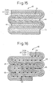
- the folded member 40 shown in FIG. 13 or FIG. 14 is obtained as follows: A green sheet for forming the solid electrolyte layer 42a is sandwiched between a green sheet for forming the cathode layer 42b and a green sheet for forming the anode layer 42c so as to form a single cell layer green sheet for forming the single cell layer 42. Next, the single cell layer green sheet is folded back and forth to form a preform. Next, this preform can be fired under predetermined atmospheric conditions so as to obtain the folded member 40 shown in FIG. 13 or FIG. 14. Further, in the folded member 40 shown in FIG. 13 or FIG. 14, the solid electrolyte layer 42a may be a compact layer or a porous layer.
- the strata of the single cell layer 42 adjoining each other in the vertical direction contact each other by the strata of the cathode layer 42b or by the strata of the anode layer 42c. Therefore, the cathode layer 42b and the anode layer 42c have to be porous layers.
- This embodiment cannot be applied to a single cell layer 42 where the cathode layer 42b and anode layer 42c are compact layers.
- the strata of the single cell layer 42 adjoining each other in the vertical direction have a passage for passing the mixed gas formed between them, so it is possible to form a folded member 40 even by a single cell layer 42 having a cathode layer 42b and anode layer 42c comprised of compact layers.
- the passage for passing the mixed gas is formed by porous layers 44 provided between strata of the single cell layer 42 adjoining each other in the vertical direction.
- porous layers 44 are preferably comprised of an alumina or other ceramic'having an open porosity of at least 20%, preferably 30 to 70%, particularly preferably 40 to 50%.
- porous layer green sheets are fired to obtain porous layers 44 of a predetermined open porosity.
- a single layer cell green sheet is sandwiched between the porous layers 44 fired in advance and the assembly is folded back and forth to form a preform.
- this may be fired under firing conditions for densification of the single cell layer green sheet so as to obtain the folded member 40 shown in FIG. 15.
- the adjoining strata of the single cell layer 42 are provided between them with a plurality of spacer members 46, 46... to form a mixed gas passage.
- the 16 may be electrical insulators or conductors since the strata forming the facing surfaces of the single cell layer 42 are both strata of the anode layer 42c or cathode layer 42b.
- the members may be shaped as rods extending in the width direction of the folded member 40 or as points.
- Each of the folded members 40 shown in FIG. 12 to FIG. 16 is provided with lead wires for taking out the electromotive force from the anode layer 42c and cathode layer 42c, is housed in a rectangular hollow container having heat resistance surrounded by a heater, and can generate power by being heated to a predetermined temperature by the heater and being supplied with mixed gas from one side of the hollow container in the arrow D direction (FIG. 12).
- a plurality of hollow containers housing the folded members 40 may be arranged in parallel or in series.
- the fuel cell according to the present invention is comprised of a single cell layer of a cathode layer, solid electrolyte layer, and anode layer stacked together or a multilayer member of a plurality of single cell layers stacked together spirally rolled up into a spiral member or folded back and forth into a folded member. Therefore, it is possible to easily increase the contact area of the anode layer and cathode layer with the mixed gas without rapidly increasing the size of the spiral member or folded member. As a result, it is possible to reduce the size of a fuel battery using the fuel cells according to the present invention.
Applications Claiming Priority (2)
| Application Number | Priority Date | Filing Date | Title |
|---|---|---|---|
| JP2002248446 | 2002-08-28 | ||
| JP2002248446A JP4249960B2 (ja) | 2002-08-28 | 2002-08-28 | 燃料電池セル |
Publications (2)
| Publication Number | Publication Date |
|---|---|
| EP1394885A1 true EP1394885A1 (de) | 2004-03-03 |
| EP1394885B1 EP1394885B1 (de) | 2008-08-20 |
Family
ID=31492567
Family Applications (1)
| Application Number | Title | Priority Date | Filing Date |
|---|---|---|---|
| EP03255236A Expired - Lifetime EP1394885B1 (de) | 2002-08-28 | 2003-08-22 | Brennstoffzelle |
Country Status (5)
| Country | Link |
|---|---|
| US (1) | US7264899B2 (de) |
| EP (1) | EP1394885B1 (de) |
| JP (1) | JP4249960B2 (de) |
| CA (1) | CA2437324A1 (de) |
| DE (1) | DE60323022D1 (de) |
Cited By (5)
| Publication number | Priority date | Publication date | Assignee | Title |
|---|---|---|---|---|
| WO2003036746A2 (en) * | 2001-10-20 | 2003-05-01 | The University Court Of The University Of St Andrews | Improvements in solid oxide fuel cells and related devices |
| WO2005064731A2 (de) * | 2003-12-23 | 2005-07-14 | Universität Stuttgart | Elektrochemische zellenanordnung in taschenförmiger bauweise |
| EP1703576A3 (de) * | 2005-03-14 | 2007-01-24 | Shinko Electric Industries Co., Ltd. | Energieerzeugungsvorrichtung mit Festoxidbrennstoffzelle |
| WO2009061294A1 (en) * | 2007-11-06 | 2009-05-14 | Nanodynamics Energy, Inc. | Tubular electrochemical cell |
| US8182959B2 (en) | 2007-11-06 | 2012-05-22 | Cp Sofc Ip, Llc | Tubular electrochemical cell |
Families Citing this family (6)
| Publication number | Priority date | Publication date | Assignee | Title |
|---|---|---|---|---|
| GB0715225D0 (en) * | 2007-08-03 | 2007-09-12 | Rolls Royce Fuel Cell Systems | A fuel cell and a method of manufacturing a fuel cell |
| JP5194943B2 (ja) * | 2008-03-28 | 2013-05-08 | 大日本印刷株式会社 | 固体酸化物形燃料電池の製造方法、及びこの方法により製造された固体酸化物形燃料電池 |
| FR2977081B1 (fr) * | 2011-06-24 | 2014-10-24 | Commissariat Energie Atomique | Electrode a diffusion gazeuse de grande capacite |
| JP5628971B1 (ja) * | 2013-06-13 | 2014-11-19 | 日本写真印刷株式会社 | マイクロ流体デバイス及び誘電泳動装置 |
| US8871394B1 (en) * | 2014-03-07 | 2014-10-28 | ZAF Energy Systems, Incorporated | Metal-air battery with reduced gas diffusion layer |
| GB201915438D0 (en) * | 2019-10-24 | 2019-12-11 | Ceres Ip Co Ltd | Metal-supported cell unit |
Citations (6)
| Publication number | Priority date | Publication date | Assignee | Title |
|---|---|---|---|---|
| US4863813A (en) * | 1988-09-15 | 1989-09-05 | Bell Communications Research, Inc. | Primary source of electrical energy using a mixture of fuel and oxidizer |
| US4988582A (en) * | 1990-05-04 | 1991-01-29 | Bell Communications Research, Inc. | Compact fuel cell and continuous process for making the cell |
| US5094928A (en) * | 1990-04-20 | 1992-03-10 | Bell Communications Research, Inc. | Modular fuel cell assembly |
| US5219673A (en) * | 1991-08-23 | 1993-06-15 | Kaun Thomas D | Cell structure for electrochemical devices and method of making same |
| US6063517A (en) * | 1997-10-16 | 2000-05-16 | Southwest Research Institute | Spiral wrapped cylindrical proton exchange membrane fuel cells and methods of making same |
| WO2003036746A2 (en) | 2001-10-20 | 2003-05-01 | The University Court Of The University Of St Andrews | Improvements in solid oxide fuel cells and related devices |
Family Cites Families (5)
| Publication number | Priority date | Publication date | Assignee | Title |
|---|---|---|---|---|
| US4876163A (en) * | 1987-12-18 | 1989-10-24 | Westinghouse Electric Corp. | Generator configuration for solid oxide fuel cells |
| JPH0562692A (ja) | 1991-09-05 | 1993-03-12 | Fuji Electric Corp Res & Dev Ltd | 固体電解質型燃料電池 |
| JPH07282823A (ja) | 1994-04-12 | 1995-10-27 | Kyocera Corp | 円筒型燃料電池セルの製造方法 |
| US6054228A (en) * | 1996-06-06 | 2000-04-25 | Lynntech, Inc. | Fuel cell system for low pressure operation |
| US7049024B2 (en) * | 2003-04-30 | 2006-05-23 | Hewlett-Packard Development Company, L.P. | Membrane electrode assemblies and method for manufacture |
-
2002
- 2002-08-28 JP JP2002248446A patent/JP4249960B2/ja not_active Expired - Fee Related
-
2003
- 2003-08-14 CA CA002437324A patent/CA2437324A1/en not_active Abandoned
- 2003-08-18 US US10/642,342 patent/US7264899B2/en active Active
- 2003-08-22 DE DE60323022T patent/DE60323022D1/de not_active Expired - Lifetime
- 2003-08-22 EP EP03255236A patent/EP1394885B1/de not_active Expired - Lifetime
Patent Citations (6)
| Publication number | Priority date | Publication date | Assignee | Title |
|---|---|---|---|---|
| US4863813A (en) * | 1988-09-15 | 1989-09-05 | Bell Communications Research, Inc. | Primary source of electrical energy using a mixture of fuel and oxidizer |
| US5094928A (en) * | 1990-04-20 | 1992-03-10 | Bell Communications Research, Inc. | Modular fuel cell assembly |
| US4988582A (en) * | 1990-05-04 | 1991-01-29 | Bell Communications Research, Inc. | Compact fuel cell and continuous process for making the cell |
| US5219673A (en) * | 1991-08-23 | 1993-06-15 | Kaun Thomas D | Cell structure for electrochemical devices and method of making same |
| US6063517A (en) * | 1997-10-16 | 2000-05-16 | Southwest Research Institute | Spiral wrapped cylindrical proton exchange membrane fuel cells and methods of making same |
| WO2003036746A2 (en) | 2001-10-20 | 2003-05-01 | The University Court Of The University Of St Andrews | Improvements in solid oxide fuel cells and related devices |
Non-Patent Citations (3)
| Title |
|---|
| "SOFCRoll An advance in Fuel Cell technology", CENTRE OF ADVANCED MATERIALS AT THE UNIVERSITY OF ST ANDREWS, pages 1, XP002989930 |
| JONES F.G.E. AND JOHN T.S. IRVINE: "Co-fired SOFC Electrode-electrolyte-electrode membrane rolls, combining tubular and planar technologies", 5TH EUROPEAN SOLID OXIDE FUEL CELL FORUM, vol. 1, 1 July 2002 (2002-07-01) - 5 July 2002 (2002-07-05), LUCERNE - SWITZERLAND, pages 123 - 131, XP002989928 |
| JONES, FRANCES G.E.: "Electrode versus electrolyte supported cell concepts", 5TH EUROPEAN SOFC FORUM, 1 May 2002 (2002-05-01) - 5 July 2002 (2002-07-05), LUCERNE -SWITSERLAND, pages 1 - 12, XP002989929 |
Cited By (11)
| Publication number | Priority date | Publication date | Assignee | Title |
|---|---|---|---|---|
| WO2003036746A2 (en) * | 2001-10-20 | 2003-05-01 | The University Court Of The University Of St Andrews | Improvements in solid oxide fuel cells and related devices |
| WO2003036746A3 (en) * | 2001-10-20 | 2004-07-01 | Univ St Andrews | Improvements in solid oxide fuel cells and related devices |
| US7569304B2 (en) | 2001-10-20 | 2009-08-04 | The University Court Of The University Of St. Andrews | Fuel cells and related devices |
| WO2005064731A2 (de) * | 2003-12-23 | 2005-07-14 | Universität Stuttgart | Elektrochemische zellenanordnung in taschenförmiger bauweise |
| WO2005064731A3 (de) * | 2003-12-23 | 2006-02-09 | Univ Stuttgart | Elektrochemische zellenanordnung in taschenförmiger bauweise |
| EP1703576A3 (de) * | 2005-03-14 | 2007-01-24 | Shinko Electric Industries Co., Ltd. | Energieerzeugungsvorrichtung mit Festoxidbrennstoffzelle |
| US7659021B2 (en) | 2005-03-14 | 2010-02-09 | Shinko Electric Industries Co., Ltd. | Power generating apparatus using solid oxide fuel cell |
| WO2009061294A1 (en) * | 2007-11-06 | 2009-05-14 | Nanodynamics Energy, Inc. | Tubular electrochemical cell |
| CN101953008A (zh) * | 2007-11-06 | 2011-01-19 | 纳诺Cp有限责任公司 | 管状电化学电池 |
| US8182959B2 (en) | 2007-11-06 | 2012-05-22 | Cp Sofc Ip, Llc | Tubular electrochemical cell |
| AU2007361299B2 (en) * | 2007-11-06 | 2014-01-09 | Nano Cp, Llc | Tubular electrochemical cell |
Also Published As
| Publication number | Publication date |
|---|---|
| DE60323022D1 (de) | 2008-10-02 |
| JP4249960B2 (ja) | 2009-04-08 |
| CA2437324A1 (en) | 2004-02-28 |
| US20040126636A1 (en) | 2004-07-01 |
| EP1394885B1 (de) | 2008-08-20 |
| US7264899B2 (en) | 2007-09-04 |
| JP2004087366A (ja) | 2004-03-18 |
Similar Documents
| Publication | Publication Date | Title |
|---|---|---|
| JP3996861B2 (ja) | 燃料電池セル及び燃料電池 | |
| KR101175599B1 (ko) | 인터커넥터용 재료, 셀간 분리 구조체 및 고체 전해질형 연료 전지 | |
| US20030148160A1 (en) | Anode-supported tubular solid oxide fuel cell stack and method of fabricating the same | |
| US9263749B2 (en) | Fuel cell | |
| CN101868875B (zh) | 横条纹型固体氧化物形燃料电池单元组及燃料电池 | |
| EP2495791B1 (de) | Brennstoffzelle, brennstoffzellenstapel, brennstoffzellenmodul und brennstoffzellenvorrichtung | |
| JP2007134230A (ja) | 燃料電池セル、燃料電池セルスタック及び燃料電池 | |
| EP1394885B1 (de) | Brennstoffzelle | |
| KR101869305B1 (ko) | 셀, 셀 스택 장치, 모듈 및 모듈 수납 장치 | |
| EP2787570A1 (de) | Zellenstapelvorrichtung, brennstoffzellenmodul, brennstoffzellenvorrichtung und verfahren zur herstellung einer zellenstapelvorrichtung | |
| JP2006302643A (ja) | 多孔質材料及び燃料電池セル並びに燃料電池 | |
| JP2012181928A (ja) | 固体酸化物形燃料電池セルおよび燃料電池モジュール | |
| US6599654B2 (en) | Fuel cell and multi-element stack therefor | |
| CN110088965B (zh) | 单电池、单电池堆装置、模块以及模块收纳装置 | |
| JP4593997B2 (ja) | 燃料電池セル用支持体及び燃料電池セル並びに燃料電池 | |
| JP2006127973A (ja) | 燃料電池セル | |
| JP4480377B2 (ja) | 燃料電池セル及び燃料電池 | |
| JP4925574B2 (ja) | 燃料電池セル及び燃料電池 | |
| JP2012178257A (ja) | 燃料電池用多孔質導電性支持体および固体酸化物形燃料電池セル | |
| JP4579527B2 (ja) | 燃料電池セル、燃料電池及び燃料電池セルの製法 | |
| CN111886737B (zh) | 单电池堆装置、模块以及模块收容装置 | |
| US9666881B2 (en) | Solid electrolyte fuel cell | |
| JP4021782B2 (ja) | 燃料電池セル | |
| JP2005190737A (ja) | 燃料電池セル用支持体及び燃料電池セル並びに燃料電池 | |
| JP4412994B2 (ja) | 燃料電池セル用支持基板及び燃料電池セル並びに燃料電池 |
Legal Events
| Date | Code | Title | Description |
|---|---|---|---|
| PUAI | Public reference made under article 153(3) epc to a published international application that has entered the european phase |
Free format text: ORIGINAL CODE: 0009012 |
|
| AK | Designated contracting states |
Kind code of ref document: A1 Designated state(s): AT BE BG CH CY CZ DE DK EE ES FI FR GB GR HU IE IT LI LU MC NL PT RO SE SI SK TR |
|
| AX | Request for extension of the european patent |
Extension state: AL LT LV MK |
|
| TPAC | Observations filed by third parties |
Free format text: ORIGINAL CODE: EPIDOSNTIPA |
|
| 17P | Request for examination filed |
Effective date: 20040820 |
|
| AKX | Designation fees paid |
Designated state(s): DE FR GB |
|
| 17Q | First examination report despatched |
Effective date: 20050323 |
|
| GRAP | Despatch of communication of intention to grant a patent |
Free format text: ORIGINAL CODE: EPIDOSNIGR1 |
|
| GRAS | Grant fee paid |
Free format text: ORIGINAL CODE: EPIDOSNIGR3 |
|
| GRAA | (expected) grant |
Free format text: ORIGINAL CODE: 0009210 |
|
| AK | Designated contracting states |
Kind code of ref document: B1 Designated state(s): DE FR GB |
|
| REG | Reference to a national code |
Ref country code: GB Ref legal event code: FG4D |
|
| REF | Corresponds to: |
Ref document number: 60323022 Country of ref document: DE Date of ref document: 20081002 Kind code of ref document: P |
|
| PLBE | No opposition filed within time limit |
Free format text: ORIGINAL CODE: 0009261 |
|
| STAA | Information on the status of an ep patent application or granted ep patent |
Free format text: STATUS: NO OPPOSITION FILED WITHIN TIME LIMIT |
|
| 26N | No opposition filed |
Effective date: 20090525 |
|
| REG | Reference to a national code |
Ref country code: FR Ref legal event code: PLFP Year of fee payment: 14 |
|
| REG | Reference to a national code |
Ref country code: FR Ref legal event code: PLFP Year of fee payment: 15 |
|
| REG | Reference to a national code |
Ref country code: FR Ref legal event code: PLFP Year of fee payment: 16 |
|
| PGFP | Annual fee paid to national office [announced via postgrant information from national office to epo] |
Ref country code: FR Payment date: 20210715 Year of fee payment: 19 |
|
| PGFP | Annual fee paid to national office [announced via postgrant information from national office to epo] |
Ref country code: GB Payment date: 20210714 Year of fee payment: 19 Ref country code: DE Payment date: 20210713 Year of fee payment: 19 |
|
| REG | Reference to a national code |
Ref country code: DE Ref legal event code: R119 Ref document number: 60323022 Country of ref document: DE |
|
| GBPC | Gb: european patent ceased through non-payment of renewal fee |
Effective date: 20220822 |
|
| PG25 | Lapsed in a contracting state [announced via postgrant information from national office to epo] |
Ref country code: FR Free format text: LAPSE BECAUSE OF NON-PAYMENT OF DUE FEES Effective date: 20220831 Ref country code: DE Free format text: LAPSE BECAUSE OF NON-PAYMENT OF DUE FEES Effective date: 20230301 |
|
| PG25 | Lapsed in a contracting state [announced via postgrant information from national office to epo] |
Ref country code: GB Free format text: LAPSE BECAUSE OF NON-PAYMENT OF DUE FEES Effective date: 20220822 |