EP1394633B1 - System zur Bilderzeugung mit Kartusche - Google Patents
System zur Bilderzeugung mit Kartusche Download PDFInfo
- Publication number
- EP1394633B1 EP1394633B1 EP03019489A EP03019489A EP1394633B1 EP 1394633 B1 EP1394633 B1 EP 1394633B1 EP 03019489 A EP03019489 A EP 03019489A EP 03019489 A EP03019489 A EP 03019489A EP 1394633 B1 EP1394633 B1 EP 1394633B1
- Authority
- EP
- European Patent Office
- Prior art keywords
- cartridge
- image forming
- forming apparatus
- storage area
- main body
- Prior art date
- Legal status (The legal status is an assumption and is not a legal conclusion. Google has not performed a legal analysis and makes no representation as to the accuracy of the status listed.)
- Expired - Lifetime
Links
- 238000000034 method Methods 0.000 claims description 81
- 238000003860 storage Methods 0.000 claims description 78
- 230000015654 memory Effects 0.000 claims description 33
- 239000000463 material Substances 0.000 claims description 19
- 238000004140 cleaning Methods 0.000 claims description 13
- 238000006243 chemical reaction Methods 0.000 claims 1
- 230000014509 gene expression Effects 0.000 description 23
- 238000010276 construction Methods 0.000 description 8
- 230000000694 effects Effects 0.000 description 5
- 238000005299 abrasion Methods 0.000 description 4
- 230000003247 decreasing effect Effects 0.000 description 4
- 230000002093 peripheral effect Effects 0.000 description 3
- 241001354243 Corona Species 0.000 description 2
- 238000005496 tempering Methods 0.000 description 2
- 239000003086 colorant Substances 0.000 description 1
- 239000000470 constituent Substances 0.000 description 1
- 230000001419 dependent effect Effects 0.000 description 1
- 230000006866 deterioration Effects 0.000 description 1
- 238000011161 development Methods 0.000 description 1
- 230000018109 developmental process Effects 0.000 description 1
- 238000010586 diagram Methods 0.000 description 1
- 239000009206 extralife Substances 0.000 description 1
- 230000006870 function Effects 0.000 description 1
- 239000000696 magnetic material Substances 0.000 description 1
- 238000004519 manufacturing process Methods 0.000 description 1
- 230000004044 response Effects 0.000 description 1
- 238000004904 shortening Methods 0.000 description 1
Images


Classifications
-
- G—PHYSICS
- G03—PHOTOGRAPHY; CINEMATOGRAPHY; ANALOGOUS TECHNIQUES USING WAVES OTHER THAN OPTICAL WAVES; ELECTROGRAPHY; HOLOGRAPHY
- G03G—ELECTROGRAPHY; ELECTROPHOTOGRAPHY; MAGNETOGRAPHY
- G03G21/00—Arrangements not provided for by groups G03G13/00 - G03G19/00, e.g. cleaning, elimination of residual charge
- G03G21/16—Mechanical means for facilitating the maintenance of the apparatus, e.g. modular arrangements
- G03G21/18—Mechanical means for facilitating the maintenance of the apparatus, e.g. modular arrangements using a processing cartridge, whereby the process cartridge comprises at least two image processing means in a single unit
- G03G21/1875—Mechanical means for facilitating the maintenance of the apparatus, e.g. modular arrangements using a processing cartridge, whereby the process cartridge comprises at least two image processing means in a single unit provided with identifying means or means for storing process- or use parameters, e.g. lifetime of the cartridge
- G03G21/1878—Electronically readable memory
- G03G21/1889—Electronically readable memory for auto-setting of process parameters, lifetime, usage
-
- G—PHYSICS
- G03—PHOTOGRAPHY; CINEMATOGRAPHY; ANALOGOUS TECHNIQUES USING WAVES OTHER THAN OPTICAL WAVES; ELECTROGRAPHY; HOLOGRAPHY
- G03G—ELECTROGRAPHY; ELECTROPHOTOGRAPHY; MAGNETOGRAPHY
- G03G15/00—Apparatus for electrographic processes using a charge pattern
- G03G15/14—Apparatus for electrographic processes using a charge pattern for transferring a pattern to a second base
- G03G15/16—Apparatus for electrographic processes using a charge pattern for transferring a pattern to a second base of a toner pattern, e.g. a powder pattern, e.g. magnetic transfer
Definitions
- This invention relates to an image forming apparatus such as a copying machine or a laser beam printer of an electrophotographic type, and a cartridge detachably attachable to the image forming apparatus.
- a known image forming apparatus using an electrophotographic recording process for example, a laser beam printer is provided with a photosensitive drum as an image bearing member rotatively driven, a charging roller as charging means for uniformly charging the surface of the photosensitive drum, a laser for exposing the surface of the photosensitive drum to light and forming an electrostatic latent image corresponding to an image signal, developing means for developing the electrostatic latent image with a toner and forming a visible image, a transferring roller for transferring the visible image (developer image) onto recording paper as a sheet, fixing means for fixing the visible image transferred onto the recording paper, cleaning means, etc.
- a laser beam printer is provided with a photosensitive drum as an image bearing member rotatively driven, a charging roller as charging means for uniformly charging the surface of the photosensitive drum, a laser for exposing the surface of the photosensitive drum to light and forming an electrostatic latent image corresponding to an image signal, developing means for developing the electrostatic latent image with a toner and forming a visible image,
- this image forming apparatus it is known to make the photosensitive drum and the charging roller integral with the cleaning means or the developing means and making them into a cartridge, make this cartridge (hereinafter referred to as the process cartridge) detachably attachable to the- image forming apparatus to thereby realize a maintenance-free image forming apparatus.
- the process cartridge detachably attachable to the- image forming apparatus to thereby realize a maintenance-free image forming apparatus.
- This interchanging work is very simple work of opening the main body of the image forming apparatus by one touch, taking out the old process cartridge from the interior of the main body of the image forming apparatus, and mounting an unused new process cartridge on the main body of the image forming apparatus, and can be carried out easily by an operator himself.
- the life (interchange time) of this process cartridge is determined chiefly by the abrasion of the photosensitive drum and the developing roller and the consumption of the toner.
- the abrasion of the photosensitive drum and the developing roller can be schematically calculated from their total number of revolutions.
- the life (interchange time) can be calculated from a total number of printed sheets proportional to the total number of revolutions.
- the consumption of the toner can be detected by toner remaining amount detecting means.
- the amount of remaining toner can be detected each time.
- the process cartridge can be arbitrarily interchanged by the user and therefore, it is desirable that the total number of printed sheets regarding the life of the photosensitive drum and the developing roller be kept in custody in the process cartridge.
- inter-sheet there are generally two methods of making the number of sheets printable within a minute different. To quicken the number of printed sheets, there are a method of increasing the rotating speed itself of the photosensitive drum, and a method of narrowing the interval between sheets being under continuous printing. This interval between the sheets will hereinafter simply be called the inter-sheet.
- this main body does not differ in the relation between the total number of revolutions and the total number of printed sheets from a main body having its rotating speed kept as it is. This is because the number of printed sheets increases in proportion to an increase in the number of revolutions per unit time.
- the life (interchange time) of the photosensitive drum, the developing roller, etc. can be correctly calculated even by a conventional calculating method, even between main bodies differing in printing speed from each other.
- the rotating speed of the photosensitive drum is equal between the respective main bodies, and the conveying speed of the sheet is also equal between the respective main bodies. Accordingly, various conditions concerning an image such as a laser applying condition and a fixing condition can be made constant and therefore, not only the image forming apparatus can be developed within a short period, but also various parts can be made common and therefore, the cost of the apparatus and the reliability of the parts can be improved.
- the inter-sheet is shortened to thereby make the number of printed sheets per unit time (a minute) different, the relation between the total number of revolutions of the photosensitive drum, the developing drum, etc. and the total number of printed sheets becomes different between the main bodies of image forming apparatuses of different features.
- the rate of the time of the inter-sheet during which an image is not printed becomes short. That is, the ratio of the time contributing to printing increases and therefore, in the main body wherein the inter-sheet is short relative to the same total number of revolutions, the total number of printed sheets becomes greater.
- the conventional calculating method is not successful between the main bodies differing in the inter-sheet from each other.
- the user has two kinds of main bodies, i.e., a main body in which the inter-sheet is short and a main body in which the inter-sheet is long. If the process cartridge has interchangeability, there is the possibility of the same process cartridge being alternately mounted on the two main bodies. In this case, there may occur the unreasonableity that the process cartridge reaches its life in one main body and does not reach its life in the other main body.
- the present invention has been made in view of the above-noted problem and an object thereof is to accurately grasp the life (interchange time) of a cartridge having interchangeability and detachably attachable to main bodies of different features.
- an object of the present invention is to accurately judge the life (interchange time) of a cartridge having interchangeability and detachably attachable to main bodies of different features.
- the image forming apparatus has a mounting portion on which a cartridge having at least some of members necessary for image forming and a storage part and detachably attachable to image forming apparatuses of different features is mounted, and a control part for judging the interchange time of the cartridge in conformity with information stored in the storage part, wherein the storage part has a storage area for storing therein information regarding the used amount in each feature of the image forming apparatuses, and the control part judges the interchange time of the cartridge in conformity with the information of the used amount in each feature stored in the storage area of the storage part.
- the cartridge is a cartridge having at least some of members necessary for image forming and a storage part, and detachably attachable to the mounting portions of image forming apparatuses of different features having a control part for judging the interchange time of the cartridge in conformity with information stored in the storage part, characterized in that the storage part has a storage area for storing therein information regarding the used amount in each feature.
- Fig. 1 is a cross-sectional view schematically showing the construction of the image forming parts of color image forming apparatuses utilizing an electrophotographic process according to a first embodiment of the present invention.
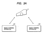
- the image forming apparatus 101 and the image forming apparatus 102 are image forming apparatuses which are the same in apparatus construction but differ in feature. In this case, the interval between sheets P being conveyed differs between the image forming apparatus 101 and the image forming apparatus 102.
- the reference numeral 1 designates rotary drum-shaped electrophotographic photosensitive members (hereinafter referred to as the photosensitive drums), the reference numeral 2 denotes primary charging rollers which are charging means, the reference numeral 3 designates cleaning means, the reference numeral 4 denotes cleaning containers, the reference numeral 5 designates transferring rollers which are transferring means, the reference numeral 6 denotes. developing devices, and the reference numeral 9 designates tension rollers.
- the reference numerals 71 to 74 denote cartridge members which are nonvolatile memories
- the reference numerals 81 to 84 designate process cartridges each having the photosensitive drum 1, the primary charging roller 2, the cleaning means 3, the cleaning container 4, the developing device 6 and the cartridge memories 71 to 74
- the reference numerals 111, 112, 113 and 114 denote mounting portions for mounting the process cartridges 81 to 84 thereon.
- the reference numerals 101 and 102 designate image forming main bodies of discrete kinds differing in feature from each other, and the letter P denotes a transferring material.
- each of the image forming apparatus 101 and 102 is of a construction which has yellow (Y) magenta (M), cyan (C) and black (Bk) image forming units arranged in tandem in succession from below, and the transferring roller 5 as a transferring member provided at the position corresponding to each image forming unit, and in which the transferring material P is conveyed by transferring belt 10, and toner images are transferred by the transferring roller 5 through the transferring belts 10 to thereby form a full-color image on the transferring material P.
- Y yellow
- M magenta
- C cyan
- Bk black
- each of these image forming units is provided with the process cartridges 81 to 84, the transferring rollers 5, the photosensitive drums 1 as image bearing members, and also rotatively driven in a counter-clockwise direction as viewed in Fig. 1 at a predetermined peripheral speed (process speed), the primary charging rollers 2 for uniformly charging the surfaces of the photosensitive drums 1, the developing devices 6 which are developing apparatuses for developing electrostatic latent images formed on the photosensitive drums 1, image exposing means, not shown, for exposing the surfaces of the photosensitive drums 1 to light to thereby form electrostatic latent images thereon, and the cleaning means 3 for removing any residual toners on the photosensitive drums 1.
- Each of the image forming apparatuses 101 and 102 has mounting portions 111 to 114 for mounting the process cartridges 81 to 84 thereon, and the process cartridges are detachably attachable to the mounting portions.
- each of the photosensitive drums 1 is a negatively charged organic photo-conductive (OPC) photosensitive member having a diameter of 30 mm, and the peripheral speed thereof is 90 mm/sec.
- OPC organic photo-conductive
- each of the primary charging rollers 2 constitutes a charging device of an AC contact charging type which follows and contacts with the photosensitive drum 1 to thereby effect charging, and the surface of the photosensitive drum 1 is charged to 600V by the primary charging roller 2 having applied thereto a bias comprising an AC voltage component of 2000 Vpp and 1000 Hz and a DC voltage component of -600V superimposed upon each other.
- the developing devices 6, as shown in Fig. 2 are provided with toner containing portions containing therein so-called nonmagnetic toners of Y, M, C and Bk not containing magnetic materials, and developing rollers rotated in a forward direction relative to the photosensitive drums 1 by a rotatively driving device, not shown, and serve to develop the electrostatic latent images formed on the photosensitive drums 1, by. a contact one-component contact developing process of applying a variable voltage to the developing rollers by the signal of a controller, not shown, and are disposed so as to be opposed to the photosensitive drums 1.
- the image exposing means are comprised of laser diodes, polygon scanners, lens units, etc., and by receiving image exposure from these image exposing means, electrostatic latent images corresponding to the first to fourth color component images (e.g. yellow, magenta, cyan and black component images) of a desired color image are formed on the photosensitive drums 1.
- first to fourth color component images e.g. yellow, magenta, cyan and black component images
- the image exposing means are polygon scanners using laser diodes.
- the writing-out of laser exposure is designed to be effected with a predetermined time delay from a position signal in the polygon scanner called BD for each scanning line in a main scanning direction (a direction orthogonal to the movement of the transferring material), and from a TOP signal starting from a switch in a conveying path in a subscanning direction (the direction of movement of the transferring material), whereby exposure can be effected on the photosensitive drums 1 in timed relationship with one another so that toner images can always be transferred to the same position on the transferring material P.
- BD position signal in the polygon scanner
- the cartridges are vertically arranged to minimize the grounded area of the image forming apparatuses.
- a front door (not shown) only is opened and closed.
- the front door is designed to be opened and closed with the transferring belt 10.
- This transferring belt 10 is in contact with the photosensitive drums 1 with the transferring material P interposed therebetween when a sheet is supplied.
- Fig. 2 typically shows the main bodies to illustrate the difference between the image forming apparatus main bodies 101 and 102 of Fig. 1 .
- These main bodies differ in the number of sheets printable within a minute from each other.
- the image forming apparatus main body 101 can print 12 sheets within a minute. This is referred to as the main body of 12 prints per minute (ppm).
- the image forming apparatus main body 102 can print 16 sheets within a minute. This is referred to as the main body of 16 prints per minute (ppm).
- the routes of the transferring materials P in the two main bodies will hereinafter be described.
- the transferring material P fed by a sheet feeding roller is moved upwardly.
- the toner image formed on the photosensitive drum 1 for the first color (Y) from below is transferred to the transferring material P while being conveyed by the transferring belt 10 through the intermediary of the transferring roller 5
- the toner images on the photosensitive drums 1 are likewise successively superimposed and transferred onto the transferring material P.
- the transferring material is directed to fixing means, not shown, where a color image is printed.
- the inter-sheet W the interval between a transferring material P and a transferring material P
- the inter-sheet W is 150 mm in the main body 101, and is 40 mm in the main body 102.
- this inter-sheet W is shortened by contriving the sheet feeding construction and the temperature tempering of the fixing device. Specifically, in the sheet feeding construction, the inter-sheet W was shortened by increasing the accuracy of the leading edge position of the sheet and the response period of a sensor for the leading edge position.
- the inter-sheet W has been shortened in such a manner as to change the temperature tempering sequence to thereby better a heat resisting grade so that even if a pressure roller is not warmed in the inter-sheet, fixing can be effected.
- the photosensitive drum is abraded in proportion to the number of revolutions thereof.
- the inter-sheet W could be shortened and therefore, the number of revolutions of the photosensitive drums per unit number of sheets can be decreased and the life of the photosensitive drums can be lengthened.
- Fig. 3A shows that a cartridge C can be mounted on both of the image forming apparatus 101 and the image forming apparatus 102.
- Fig. 3B is a block diagram showing the relation between the cartridge memory parts 71-74 and the control part (CPU) of the image forming apparatus main body.
- the cartridge memory part has a storage element M for storing data therein and a memory control part 20 for controlling the reading-out and writing-in of data relative to the storage element M.
- the storage element M can be a nonvolatile memory, and for example, NVRAM, EEPROM, FeRAM or the like can be used as the storage element M.
- This storage element M is provided with storage areas for respective ones of the image forming apparatus main body 101 and the image forming apparatus main body 102 differing in feature from each other.
- As the storage areas there are a used amount information (number of recorded sheets) storage area 11 for the main bodies 101 of different features, a maximum used amount (number of recorded sheets) threshold value storage area 12 for the main bodies 101 of different features, a used amount information (number of recorded sheets) storage area 21 for the main bodies of different features, and a maximum used amount information (number of recorded sheets) threshold value storage area 22 for the main bodies 102 of different features.
- the maximum used amount threshold value information refers to information corresponding to the upper limit of the number of recorded sheets (used amount) recordable, for example, by the use of the image forming apparatus, and if the result of the calculation of the number of recorded sheets which is the life value of the process cartridge to be described below exceeds this threshold value when the process cartridge is inserted into each main body, the main body notifies of the life of the process cartridge C.
- the storage element M further has a storage area 16 for information regarding the end of life (history information) indicating that the cartridge C has reached the end of its life.
- the history information indicating that the cartridge C has reached the end of its life is stored in this storage area, the information can be read out to thereby find the state of the cartridge C, and when a process cartridge unknown to the main body is inserted, the life can be judged on the spot without any extra life calculation being done.
- This information indicative of the end of the life of the cartridge C may be bit information such as 0 or 1, or information indicative of a particular value may be written in.
- the control part (CPU 14) of the image forming apparatus main body will now be described.
- the reference numeral 13 designates a sheet feeding sensor counter which reads the timing of sheet feeding by reading a signal from a sheet feeding sensor (not shown) in the image forming apparatus, and counts fed sheets. Also, a signal indicative of being the image forming apparatus main body 101 is transmitted from the control part (CPU 14) of the image forming apparatus to the memory control part 20 of the process cartridge C. Further, a count value (number of recorded sheets) counted on the basis of a signal from the sheet feeding sensor is transmitted from the control part (CPU 14) to the memory control part 20 of the cartridge memory part. This counted and integrated value is a value corresponding to the used amount of the process cartridge.
- the above-mentioned count value is transmitted from the control part (CPU 14) of the image forming apparatus main body, for example, at predetermined timing after the termination of printing, and is written into the storage element M through the memory control part 20 of the cartridge memory part.
- the timing at which the count value is written into the storage element is not limited to after the termination of printing, but can be suitable timing at a point of time whereat the recording operation of the image forming apparatus main body has been completed.
- the CPU 14 reads out the threshold value information stored in advance in the maximum number of recorded sheets storage area of the storage element M of the cartridge C for the main body 101 and the count value written in the number of recorded sheets storage area for the main body 101, and compares the latter with the threshold value information and judges whether the cartridge C has reached the end of its life. If it is judged that the cartridge C has reached the end of its life, the CPU 14 turns on a lamp 15 for notifying of the end of life according to a signal indicative of the end of life, and also transmits history information indicative of the end of life to the cartridge memory part, and writes it into an end of life information storage area 16 through the memory control part.
- the cartridge C When the cartridge C is mounted on the image forming apparatus 102, as when it is mounted on the image forming apparatus 101, a signal is transmitted from the control part (not shown) of the image forming apparatus 102 to the memory control part 20 of the cartridge memory part, and the memory control part 20 stores information regarding the image forming apparatus 102 into the storage area for the image forming apparatus 102.
- a method of displaying the end of life use may be made of a method of displaying by a lamp (display device) as shown, or a method of transmitting an image forming signal to an external apparatus and causing a display part such as a display in the external apparatus to display.
- the main body 101 and the main body 102 differ in the inter-sheet length from each other as previously described, and differ in process speed from each other. Accordingly, it is necessary to effect life (interchange time) judgment conforming to the expression (3).
- the expression (7) is a life calculating expression in the main body 101.
- the expression (8) is a life calculating expression in the main body 102.
- these expressions are used properly in the respective main bodies, whereby in whichever main body they are substituted, the life can be accurately converted and found.
- the expression (7) is the expression when the cartridge is mounted on the main body 101, and accurately finds the used amount by converting the number of recorded sheets in the main body 102 into the number of recorded sheets in the main body 101 by the use of the ratio between the maximum number of sheets (number of sheets threshold value) 9000 which can be supplied in the main body 101 and the maximum number of sheets (number of sheets threshold value) 12000 which can be supplied in the main body 102.
- the expression (8) is the expression when the cartridge is mounted on the main body 102, and accurately finds the used amount by converting the number of recorded sheets in the main body 101 into the number of recorded sheets in the main body 102 by the use of the ratio between the maximum number of sheets (number of sheets threshold value) 9000 which can be supplied in the main body 101 and the maximum number of sheets (number of sheets threshold value) 12000 which can be supplied in the main body 102.
- the number of recorded sheets supplied in the main body 102 is stored in a used amount information storage area 21 for the main body 102 shown in Fig. 3B .
- the number of recorded sheets supplied in the main body 101 is stored in a used amount information storage area 11 for the main body 101 shown in Fig. 3B .
- the number of recorded sheets supplied in the main body 102 is read out from the storage area 21 of the storage element M of the cartridge C in accordance with the expression (7), and is converted into a number of sheets corresponding to that in the main body 101 by the use of the ratio 9000/12000 between the threshold values of the numbers of recorded sheets, and the number of recorded sheets supplied in the main body 101 is added to that value. If this total number of sheets exceeds 9000 sheets which is the number of sheets threshold value in the main body 101, the CPU 14 of the main body 101 in Fig. 3B judges it and turns on the lamp 15 for notifying of the end of life and also causes history information indicative of the end of life to be stored in the storage area 16 for end of life signal information in the cartridge memory.
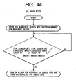
- the flow chart of Fig. 4A for the main body 101 is a flow chart of life judgment (a case following the expression (7)) in a state in which the cartridge has been mounted on the main body 101
- the flow chart of Fig. 4B for the main body 102 is a flow chart of life (interchange time) judgment (a case following the expression (8)) in a state in which the cartridge has been mounted on the main body 102.
- a second embodiment relates to a discrete main body 103 in which the charging process has been changed from an AC bias process to a DC bias process and the life of the photosensitive members has been lengthened, and will hereinafter be described with reference to Fig. 5 .
- Fig. 5 typically shows the main bodies to illustrate the difference between the image forming apparatus main bodies 101 and 103.
- the main body 101 is the same main body as the main body 101 in the first embodiment, and an AC bias is applied to the charging rollers.
- a DC bias is applied to the charging rollers.
- the primary charging rollers 2 of the main body 101 constitute a charging apparatus of an AC contact charging type which follows and contacts with the photosensitive drums 1 to thereby effect charging, and the surfaces of the photosensitive drums 1 are charged to -600V by the primary charging rollers 2 to which is applied a bias comprising an AC voltage component of 2000 Vpp and 1000 Hz and a DC voltage component of -600V superimposed upon each other.
- the primary charging rollers 2 of the main body 103 constitute a charging apparatus of a DC contact charging type which follows and contacts with the photosensitive drums 1 to thereby effect charging, and the surfaces of the photosensitive drums 1 are charged to -600V by the primary charging rollers 2 to which a DC voltage of -1100V is applied.
- each of the photosensitive drums 1 is a negatively charged OPC photosensitive member having a diameter of 30 mm, and the peripheral speed thereof is 90 mm/sec.
- the AC charging process of the main body 101 is great in discharge amount.
- the deterioration of the surfaces of the photosensitive drums is quickened in proportion to the amount of discharge received. That is, in the main body 101, the photosensitive drums are more liable to be abraded than in the main body 103.
- the life (interchange time) as the process cartridge differs between the two main bodies.
- the memory of the process cartridge is used to control the life (interchange time) in conformity with the respective main bodies.
- the main body 101 and the main body 103 differ in the life (interchange time) of the photosensitive drums due to the rubbing of the transferring portion. Accordingly, the life (interchange time) is judged by the following expressions.
- the number of sheets threshold value which can be supplied in the main body 101 as Max 101 is 9000 sheets.
- the life through which sheets can be supplied in the main body 103 has decreased the abrasion of the photosensitive drums and has become 14000 sheets. So, assuming 14000 sheets as Max 103, as in the first embodiment, proper life (interchange time) can be judged in the respective main bodies.
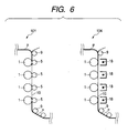
- a third embodiment relates to a discrete main body 104 in which the rubbing pressure between the photosensitive drums and the transferring material P is decreased to thereby lengthen the life of the photosensitive drums, and will hereinafter be described with reference to Fig. 6 .
- Fig. 6 typically shows the main bodies to illustrate the difference between the image forming apparatus main bodies 101 and 104.
- the main body 101 is the same main body as the main body 101 in the first embodiment, and is provided with transferring rollers 5 as transferring members, and the transferring material P is conveyed by a transferring belt 10 and toner images are transferred by the transferring rollers 5 through the transferring belt 10.
- the main body 104 is provided with transferring coronas 18 as transferring members.
- the transferring rollers 5 are pressed against the photosensitive drums 1 with the transferring belt 10 interposed therebetween with total pressure of 1 kg.
- the transferring coronas 18 are in non-contact and the transferring belt 10 is lightly in contact with the photosensitive drums 1.
- the transferring belt 10 is in contact with the photosensitive drums 1 with the transferring material P interposed therebetween when sheets are supplied.
- the main body 101 is higher in contact pressure than the main body 104 and therefore, the photosensitive drums 1 are liable to rub against the transferring belt 10 and the photosensitive drums 1 are liable to be abraded.
- the main body 101 and the main body 104 have a difference in the life of the photosensitive drums 1 due to the rubbing in the transferring part. So, when the same process cartridges are mounted on the respective main bodies, the life (interchange time) as the process cartridge differs between the two main bodies. So, as in the first embodiment, the memory of the process cartridge is used to control the life (interchange time) in conformity with the respective main bodies.
- the main body 101 and the main body 104 differ in the life (interchange time) of the photosensitive drums from each other due to the rubbing in the transferring part. Accordingly, life (interchange time) judgment is effected on the basis of the following expressions.
- the number of sheets threshold value which can be supplied in the main body 101 as Max 101 is 9000 sheets.
- the life through which sheets can be supplied in the main body 104 decreased the abrasion of the photosensitive drums and became 10000 sheets. So, assuming 10000 sheets as Max 104, as in the first embodiment, a proper life (interchange time) can be judged in the respective main bodies.
- color image forming apparatuses have been described as an example, the present invention can also be applied to a monochromatic image forming apparatus.
- a cartridge having a photosensitive drum which is an image bearing member, a primary charging roller, cleaning means, a cleaning container, a developing device and a storage part has been described as an example of the cartridge, the construction of the cartridge is not restricted thereto, but the present invention is also applicable, for example, to a cartridge having at least a developing device and a storage part.
- the used amount information thereof in the main bodies is stored in a storage medium provided on the cartridge, and even if the cartridge is mounted on and used in main bodies of different features, the life (interchange time) of the cartridge can be grasped accurately.
- the used amount information when a cartridge having interchangeability has been inserted into main bodies of different features is stored in a storage medium provided on the cartridge, and it becomes possible to accurately judge the life (interchange time) of the cartridge from the used amount of the main body itself on which the cartridge is mounted and the used amount of the other main body
- a life (interchange time) corresponding to the main body can be judged accurately relative also to the different kinds of main bodies.
- history information indicating that a cartridge has reached the end of its life can also be stored in the storage medium of the cartridge to thereby effect life (interchange time) judgment on the spot when the cartridge has been mounted.
Landscapes
- Physics & Mathematics (AREA)
- General Physics & Mathematics (AREA)
- Engineering & Computer Science (AREA)
- Computer Vision & Pattern Recognition (AREA)
- Control Or Security For Electrophotography (AREA)
- Electrophotography Configuration And Component (AREA)
Claims (14)
- System zum Erzeugen eines Bildes, wobei das System Folgendes aufweist:eine Bilderzeugungsvorrichtung (101), die einen Befestigungsabschnitt (111 bis 114) aufweist, an welchem eine Kartusche (81 bis 84) abnehmbar befestigt ist, undeine Kartusche (81 bis 84), die abnehmbar anbringbar an und austauschbar zwischen der Bilderzeugungsvorrichtung (101) und einer anderen Bilderzeugungsvorrichtung (102 bis 104) ist, und einige Bauelemente (1, 2, 3, 4, 6), die zur Bilderzeugung notwendig sind, und einen Speicherteil (71 bis 74) mit Speicherbereichen (11, 12, 21, 22) zum darin Speichern von Informationen und einen Speichersteuerteil (20) aufweist,wobei ein Fall eines Anbringens der Kartusche an die eine Bilderzeugungsvorrichtung in einer kürzeren Lebensdauer der Kartusche resultiert, im Vergleich zu einem Fall eines Anbringens der Kartusche an die andere Bilderzeugungsvorrichtung, wenn jeweils eine selbe Menge an Bildern in beiden Fällen gedruckt wird, so dass ein Nutzungsgrad der Kartusche in einem Fall, bei dem ein Bild unter einer Bedingung erzeugt ist, unter welcher die Kartusche an der einen Bilderzeugungsvorrichtung angebracht ist, von einem Nutzungsgrad der Kartusche in einem Fall, bei dem ein Bild unter einer Bedingung erzeugt ist, unter welcher die Kartusche an der anderen Bilderzeugungsvorrichtung angebracht ist, verschieden ist,wobei der Speicherteil einen ersten Speicherbereich (11), der konfiguriert ist, um darin Informationen zu speichern, die sich auf den Nutzungsgrad der Kartusche beziehen, wenn die Kartusche an der einen Bilderzeugungsvorrichtung angebracht ist, und einen von dem ersten Speicherbereich (11) verschiedenen zweiten Speicherbereich (21) aufweist, der konfiguriert ist, um darin Informationen zu speichern, die sich auf den Nutzungsgrad der Kartusche beziehen, wenn die Kartusche an der anderen Bilderzeugungsvorrichtung angebracht ist;wobei der Speichersteuerteil (20) konfiguriert ist, umden ersten Speicherbereich (11) in einem Fall auszuwählen, bei dem die Kartusche an der einen Bilderzeugungsvorrichtung angebracht ist, und um den zweiten Speicherbereich (21) in einem Fall auszuwählen, bei dem die Kartusche an der anderen Bilderzeugungsvorrichtung angebracht ist,ein Schreiben der Informationen, die sich auf den Nutzungsgrad der Kartusche beziehen, in den ausgewählten ersten oder zweiten Speicherbereich (11, 21) zu steuern, undein Auslesen der Informationen aus dem Speicherteil zu steuern,wobei die Bilderzeugungsvorrichtung einen Steuerteil (14) aufweist, der konfiguriert ist, um über den Speichersteuerteil (20) die auf den Nutzungsgrad der Kartusche bezogenen jeweiligen Informationen in und aus dem Speicherteil der Kartusche zu schreiben und zu lesen, und um eine Austauschzeit der Kartusche, die sich auf die Lebensdauer der Kartusche bezieht, durch Verarbeiten der in dem ersten Speicherbereich gespeicherten Informationen und der in dem zweiten Speicherbereich gespeicherten Informationen zu bestimmen.
- System nach Anspruch 1, wobei der Steuerteil (14) konfiguriert ist, um Informationen zum Bestimmen der Austauschzeit der Kartusche gemäß in dem ersten Speicherbereich (11) gespeicherten Informationen, die sich auf einen Nutzungsgrad der Kartusche beziehen, wenn sie an der einen Bilderzeugungsvorrichtung angebracht ist, und Informationen zu berechnen, die durch Durchführen eines Umwandlungsprozesses bezüglich Informationen erhalten werden, die sich auf den Nutzungsgrad der Kartusche beziehen, wenn sie an der anderen Bilderzeugungsvorrichtung angebracht ist.
- System nach Anspruch 2, wobei der Speicherteil ferner ein Speichergebiet (12, 22) zum darin Speichern von Information aufweist, die sich auf einen Schwellenwert beziehen, der eine obere Grenze des Nutzungsgrads der Kartusche in jeder der einen Bilderzeugungsvorrichtung und der anderen Bilderzeugungsvorrichtung darstellt, an welcher die Kartusche angebracht ist, und
wobei der Steuerteil (14) konfiguriert ist, um die Informationen zum Bestimmen der Austauschzeit der Kartusche und die Informationen, die sich auf den Schwellenwert beziehen, miteinander zu vergleichen, und konfiguriert ist, um gemäß den Ergebnissen des Vergleichs zu bestimmen, ob die Kartusche die Austauschzeit davon erreicht hat. - System nach Anspruch 3, wobei der Speicherteil ferner ein Speichergebiet (16) zum darin Speichern von Verlaufsinformationen aufweist, die anzeigen, dass die Kartusche die Austauschzeit davon erreicht hat, und
wobei, wenn der Steuerteil (14) bestimmt, dass die Kartusche die Austauschzeit davon erreicht hat, der Steuerteil (14) konfiguriert ist, um in das Speichergebiet zum darin Speichern der Verlaufsinformationen Verlaufsinformationen zu schreiben, die anzeigen, dass die Kartusche die Austauschzeit davon erreicht hat. - System nach Anspruch 1, wobei die Informationen, die sich auf den Nutzungsgrad der Kartusche beziehen, die Anzahl von aufgenommenen Blättern in der Bilderzeugungsvorrichtung darstellen.
- System nach Anspruch 1, wobei die für eine Bilderzeugung notwendigen Bauelemente ein Bildträgerbauelement (1), ein Ladebauelement (2) zum Laden des Bildträgerbauelements, ein Reinigungsbauelement (3, 4) zum Reinigen des Bildträgerbauelements, und eine Entwicklungsvorrichtung (6) zum Zuführen eines Entwicklers zu dem Bildträgerbauelement aufweist.
- System nach Anspruch 1, wobei ein Beförderungsintervall von Übertragungsmaterialien in der einen Bilderzeugungsvorrichtung von einem Beförderungsintervall (W) von Übertragungsmaterialien (P) in der anderen Bilderzeugungsvorrichtung verschieden ist.
- System nach Anspruch 6, wobei ein Ladeprozess des Ladebauelements (2) in der einen Bilderzeugungsvorrichtung von einem Ladeprozess des Ladebauelements (2) in der anderen Bilderzeugungsvorrichtung verschieden ist.
- System nach Anspruch 6, wobei ein Kontaktdruck des Übertragungsbauelements (5, 18) in der einen Bilderzeugungsvorrichtung von einem Kontaktdruck des Übertragungsbauelements (5, 18) in der anderen Bilderzeugungsvorrichtung verschieden ist.
- Kartusche (81 bis 84), die zur Bilderzeugung verwendet wird, wobei die Kartusche abnehmbar anbringbar an und austauschbar zwischen einer ersten Bilderzeugungsvorrichtung (101) und einer zweiten Bilderzeugungsvorrichtung (102 bis 104) ist, und einige Bauelemente (1, 2, 3, 4, 6), die zur Bilderzeugung notwendig sind, und einen Speicherteil (71 bis 74) mit Speicherbereichen (11, 12, 21, 22) zum darin Speichern von Informationen und einen Speichersteuerteil (20) aufweist,
wobei ein Fall eines Anbringens der Kartusche an die erste Bilderzeugungsvorrichtung in einer kürzeren Lebensdauer der Kartusche resultiert, im Vergleich zu einem Fall eines Anbringens der Kartusche an die zweite Bilderzeugungsvorrichtung, wenn jeweils eine selbe Menge an Bildern in beiden Fällen gedruckt wird, so dass ein Nutzungsgrad der Kartusche in einem Fall, bei dem ein Bild unter einer Bedingung erzeugt wird, unter welcher die Kartusche an der ersten Bilderzeugungsvorrichtung angebracht ist, von einem Nutzungsgrad der Kartusche in einem Fall, bei dem ein Bild unter einer Bedingung erzeugt wird, unter welcher die Kartusche an der zweiten Bilderzeugungsvorrichtung angebracht ist, verschieden ist,
wobei der Speicherteil einen ersten Speicherbereich (11), der konfiguriert ist, um darin erste Informationen zu speichern, die sich auf den Nutzungsgrad der Kartusche beziehen, wenn eine Kartusche an der ersten Bilderzeugungsvorrichtung angebracht ist, und einen zweiten Speicherbereich (21) aufweist, der konfiguriert ist, um darin zweite Informationen zu speichern, die sich auf den Nutzungsgrad der Kartusche beziehen, wenn eine Kartusche an der zweiten Bilderzeugungsvorrichtung angebracht ist; und
wobei der Speichersteuerteil (20) konfiguriert ist, um
den ersten Speicherbereich (11) in einem Fall auszuwählen, bei dem die Kartusche an der einen Bilderzeugungsvorrichtung angebracht ist, und um den zweiten Speicherbereich (21) in einem Fall auszuwählen, bei dem die Kartusche an der anderen Bilderzeugungsvorrichtung angebracht ist,
ein Schreiben der Informationen, die sich auf den Nutzungsgrad der Kartusche beziehen, in den ausgewählten ersten oder zweiten Speicherbereich (11, 21) zu steuern, und
ein Auslesen der in dem ersten Speicherbereich gespeicherten Informationen und der in dem zweiten Speicherbereich (11, 21) gespeicherten Informationen getrennt von den in dem ersten Speicherbereich gespeicherten Informationen für eine Verarbeitung zu steuern, um einen Nutzungsgrad der Kartusche zu bestimmen. - Kartusche nach Anspruch 10, wobei der Speicherteil ferner Speicherbereiche zum darin Speichern von Informationen aufweist, die sich auf Schwellenwerte beziehen, die obere Grenzen des Nutzungsgrads von jeder der ersten Bilderzeugungsvorrichtung und der zweiten Bilderzeugungsvorrichtung darstellen.
- Kartusche nach Anspruch 10, wobei der Speicherteil ferner einen Speicherbereich (16) zum darin Speichern von Verlaufsinformationen aufweist, die anzeigen, dass die Kartusche die Austauschzeit erreicht hat.
- Kartusche nach Anspruch 10, wobei die zur Bilderzeugung notwendigen Bauelemente ein Bildträgerbauelement (1), ein Ladebauelement (2) zum Laden des Bildträgerbauelements, ein Reinigungsbauelement (3, 4) zum Reinigen des Bildträgerbauelements, und eine Entwicklungsvorrichtung (6) zum Zuführen eines Entwicklers zu dem Bildträgerbauelement aufweist.
- Kartusche nach Anspruch 10, wobei die Informationen bezüglich des Nutzungsgrads der Kartusche in jeder der ersten Bilderzeugungsvorrichtung und der zweiten Bilderzeugungsvorrichtung eine Anzahl von Blätter darstellen.
Applications Claiming Priority (4)
| Application Number | Priority Date | Filing Date | Title |
|---|---|---|---|
| JP2002253899 | 2002-08-30 | ||
| JP2002253899 | 2002-08-30 | ||
| JP2003302521A JP4298434B2 (ja) | 2002-08-30 | 2003-08-27 | 画像形成装置 |
| JP2003302521 | 2003-08-27 |
Publications (2)
| Publication Number | Publication Date |
|---|---|
| EP1394633A1 EP1394633A1 (de) | 2004-03-03 |
| EP1394633B1 true EP1394633B1 (de) | 2010-11-03 |
Family
ID=31497701
Family Applications (1)
| Application Number | Title | Priority Date | Filing Date |
|---|---|---|---|
| EP03019489A Expired - Lifetime EP1394633B1 (de) | 2002-08-30 | 2003-08-28 | System zur Bilderzeugung mit Kartusche |
Country Status (6)
| Country | Link |
|---|---|
| US (1) | US6954596B2 (de) |
| EP (1) | EP1394633B1 (de) |
| JP (1) | JP4298434B2 (de) |
| KR (1) | KR100555001B1 (de) |
| CN (1) | CN1288510C (de) |
| DE (1) | DE60334763D1 (de) |
Families Citing this family (13)
| Publication number | Priority date | Publication date | Assignee | Title |
|---|---|---|---|---|
| JP4108065B2 (ja) * | 2004-06-16 | 2008-06-25 | シャープ株式会社 | 画像形成装置 |
| KR100823253B1 (ko) * | 2004-09-02 | 2008-04-17 | 삼성전자주식회사 | 이미지 형성 장치 및 이미지 형성장치의 저장부 |
| CN1746783B (zh) * | 2004-09-10 | 2012-03-28 | 佳能株式会社 | 图像形成装置及盒 |
| JP4810205B2 (ja) * | 2005-11-30 | 2011-11-09 | 株式会社リコー | 画像形成装置及び画像形成システム |
| JP2007171799A (ja) * | 2005-12-26 | 2007-07-05 | Fuji Xerox Co Ltd | 画像形成装置、像形成ユニット、像形成ユニットの交換方向、及び像形成ユニットの製造方法 |
| KR100863252B1 (ko) | 2008-02-29 | 2008-10-15 | 삼성전자주식회사 | 현상기와 그 메모리 유닛 및 화상형성장치 |
| JP4676523B2 (ja) * | 2008-09-17 | 2011-04-27 | シャープ株式会社 | 画像形成装置 |
| JP5834640B2 (ja) * | 2011-09-02 | 2015-12-24 | ブラザー工業株式会社 | 画像形成装置及びプログラム |
| JP6685756B2 (ja) * | 2016-02-17 | 2020-04-22 | キヤノン株式会社 | 画像形成装置及びその制御方法、並びにプログラム |
| JP6759748B2 (ja) * | 2016-06-22 | 2020-09-23 | コニカミノルタ株式会社 | 画像形成装置 |
| JP6965513B2 (ja) * | 2016-12-15 | 2021-11-10 | コニカミノルタ株式会社 | 画像形成装置、プログラム、および、画像形成システム |
| JP7106295B2 (ja) | 2018-02-28 | 2022-07-26 | キヤノン株式会社 | 画像形成装置 |
| JP7413799B2 (ja) | 2020-01-29 | 2024-01-16 | ブラザー工業株式会社 | 画像形成装置、画像形成システム、画像形成装置の制御方法及びプログラム |
Family Cites Families (9)
| Publication number | Priority date | Publication date | Assignee | Title |
|---|---|---|---|---|
| US5184178A (en) * | 1988-09-13 | 1993-02-02 | Canon Kabushiki Kaisha | Image recording apparatus having an interchangeable cartridge |
| US4961088A (en) * | 1989-04-20 | 1990-10-02 | Xerox Corporation | Monitor/warranty system for electrostatographic reproducing machines using replaceable cartridges |
| JP2897494B2 (ja) * | 1991-10-04 | 1999-05-31 | キヤノン株式会社 | プロセスカートリッジ |
| JP3270121B2 (ja) * | 1992-06-30 | 2002-04-02 | キヤノン株式会社 | 画像形成装置 |
| US6128448A (en) * | 1998-12-03 | 2000-10-03 | Hewlett-Packard Company | Method and apparatus for toner level monitoring and motion sensing |
| JP2001175133A (ja) | 1999-12-15 | 2001-06-29 | Canon Inc | 現像剤の残量及びその他の消耗品の使用状況報知システム及び画像形成装置 |
| JP2001215862A (ja) * | 2000-01-28 | 2001-08-10 | Canon Inc | 画像形成装置及びこの画像形成装置に着脱可能なカートリッジ |
| US7082660B2 (en) * | 2001-08-24 | 2006-08-01 | Canon Kabushiki Kaisha | Recycling method and image forming apparatus manufactured using recycling method |
| US6792216B2 (en) * | 2002-12-19 | 2004-09-14 | Hewlett-Packard Development Company, L.P. | System for estimating the remaining life of a print cartridge |
-
2003
- 2003-08-27 JP JP2003302521A patent/JP4298434B2/ja not_active Expired - Fee Related
- 2003-08-28 US US10/649,835 patent/US6954596B2/en not_active Expired - Fee Related
- 2003-08-28 EP EP03019489A patent/EP1394633B1/de not_active Expired - Lifetime
- 2003-08-28 DE DE60334763T patent/DE60334763D1/de not_active Expired - Lifetime
- 2003-08-29 KR KR1020030060079A patent/KR100555001B1/ko active IP Right Grant
- 2003-08-29 CN CNB03157923XA patent/CN1288510C/zh not_active Expired - Fee Related
Also Published As
| Publication number | Publication date |
|---|---|
| KR20040021537A (ko) | 2004-03-10 |
| US6954596B2 (en) | 2005-10-11 |
| KR100555001B1 (ko) | 2006-02-24 |
| JP2004110012A (ja) | 2004-04-08 |
| CN1492287A (zh) | 2004-04-28 |
| DE60334763D1 (de) | 2010-12-16 |
| CN1288510C (zh) | 2006-12-06 |
| JP4298434B2 (ja) | 2009-07-22 |
| EP1394633A1 (de) | 2004-03-03 |
| US20040091274A1 (en) | 2004-05-13 |
Similar Documents
| Publication | Publication Date | Title |
|---|---|---|
| US8422897B2 (en) | Image forming apparatus | |
| EP1394633B1 (de) | System zur Bilderzeugung mit Kartusche | |
| US6493519B2 (en) | Image forming apparatus having a plurality of image forming stations, and unit detachably mountable on the apparatus | |
| US8406640B2 (en) | Toner cartridge and control method of displaying the residual toner quantity in the same toner cartridge | |
| US5822646A (en) | Image forming apparatus | |
| US5956541A (en) | Controlling image formation based on amount of developer recovered | |
| US5771420A (en) | Life detecting system for detecting the useful life of a process unit | |
| US10401752B2 (en) | Image forming apparatus | |
| JP6554775B2 (ja) | 画像形成装置 | |
| US9042744B2 (en) | Image forming apparatus | |
| JP4403686B2 (ja) | 画像形成装置 | |
| JP4948100B2 (ja) | トナー消費予測量算出方法、トナー消費予測量算出装置、および画像形成装置 | |
| US6931218B2 (en) | Image forming apparatus and control method therefor, process cartridge and memory device | |
| JP2004294761A (ja) | トナー消費量演算装置および方法と画像形成装置 | |
| US10656554B2 (en) | Image forming apparatus | |
| JP3566468B2 (ja) | 感光体の寿命検知方法、画像形成装置、及びプロセスカートリッジ | |
| JP4882387B2 (ja) | 画像形成装置およびその画像形成方法 | |
| JP4269017B2 (ja) | 画像形成装置ならびにそれに用いる消耗品、その消耗品の判断方法 | |
| JP2002268479A (ja) | 画像形成装置 | |
| JP2010175831A (ja) | 画像形成装置、寿命判定方法、及び寿命判定制御プログラム | |
| JP2002006692A (ja) | 画像形成装置 | |
| JP2002082578A (ja) | 画像形成方法および画像形成装置 | |
| JP4337319B2 (ja) | 画像形成装置、像担持体の寿命検知方法 | |
| JP2004294762A (ja) | トナー消費量演算装置および方法と画像形成装置 | |
| JP3639239B2 (ja) | 画像形成装置 |
Legal Events
| Date | Code | Title | Description |
|---|---|---|---|
| PUAI | Public reference made under article 153(3) epc to a published international application that has entered the european phase |
Free format text: ORIGINAL CODE: 0009012 |
|
| AK | Designated contracting states |
Kind code of ref document: A1 Designated state(s): AT BE BG CH CY CZ DE DK EE ES FI FR GB GR HU IE IT LI LU MC NL PT RO SE SI SK TR |
|
| AX | Request for extension of the european patent |
Extension state: AL LT LV MK |
|
| 17P | Request for examination filed |
Effective date: 20040714 |
|
| 17Q | First examination report despatched |
Effective date: 20040826 |
|
| AKX | Designation fees paid |
Designated state(s): CH DE FR GB IT LI |
|
| 17Q | First examination report despatched |
Effective date: 20040826 |
|
| RTI1 | Title (correction) |
Free format text: SYSTEM FOR FORMING AN IMAGE WITH CARTRIDGE |
|
| GRAP | Despatch of communication of intention to grant a patent |
Free format text: ORIGINAL CODE: EPIDOSNIGR1 |
|
| GRAS | Grant fee paid |
Free format text: ORIGINAL CODE: EPIDOSNIGR3 |
|
| RIN1 | Information on inventor provided before grant (corrected) |
Inventor name: SAITO, MASANOBU Inventor name: HIRAJIMA, MAREHIKO |
|
| GRAA | (expected) grant |
Free format text: ORIGINAL CODE: 0009210 |
|
| AK | Designated contracting states |
Kind code of ref document: B1 Designated state(s): CH DE FR GB IT LI |
|
| REG | Reference to a national code |
Ref country code: GB Ref legal event code: FG4D |
|
| REG | Reference to a national code |
Ref country code: CH Ref legal event code: EP |
|
| REF | Corresponds to: |
Ref document number: 60334763 Country of ref document: DE Date of ref document: 20101216 Kind code of ref document: P |
|
| PLBE | No opposition filed within time limit |
Free format text: ORIGINAL CODE: 0009261 |
|
| STAA | Information on the status of an ep patent application or granted ep patent |
Free format text: STATUS: NO OPPOSITION FILED WITHIN TIME LIMIT |
|
| 26N | No opposition filed |
Effective date: 20110804 |
|
| REG | Reference to a national code |
Ref country code: DE Ref legal event code: R097 Ref document number: 60334763 Country of ref document: DE Effective date: 20110804 |
|
| PG25 | Lapsed in a contracting state [announced via postgrant information from national office to epo] |
Ref country code: IT Free format text: LAPSE BECAUSE OF FAILURE TO SUBMIT A TRANSLATION OF THE DESCRIPTION OR TO PAY THE FEE WITHIN THE PRESCRIBED TIME-LIMIT Effective date: 20101103 |
|
| REG | Reference to a national code |
Ref country code: CH Ref legal event code: PL |
|
| PG25 | Lapsed in a contracting state [announced via postgrant information from national office to epo] |
Ref country code: CH Free format text: LAPSE BECAUSE OF NON-PAYMENT OF DUE FEES Effective date: 20110831 Ref country code: LI Free format text: LAPSE BECAUSE OF NON-PAYMENT OF DUE FEES Effective date: 20110831 |
|
| REG | Reference to a national code |
Ref country code: FR Ref legal event code: PLFP Year of fee payment: 13 |
|
| PGFP | Annual fee paid to national office [announced via postgrant information from national office to epo] |
Ref country code: DE Payment date: 20150831 Year of fee payment: 13 Ref country code: GB Payment date: 20150826 Year of fee payment: 13 |
|
| PGFP | Annual fee paid to national office [announced via postgrant information from national office to epo] |
Ref country code: FR Payment date: 20150826 Year of fee payment: 13 |
|
| REG | Reference to a national code |
Ref country code: DE Ref legal event code: R119 Ref document number: 60334763 Country of ref document: DE |
|
| GBPC | Gb: european patent ceased through non-payment of renewal fee |
Effective date: 20160828 |
|
| REG | Reference to a national code |
Ref country code: FR Ref legal event code: ST Effective date: 20170428 |
|
| PG25 | Lapsed in a contracting state [announced via postgrant information from national office to epo] |
Ref country code: DE Free format text: LAPSE BECAUSE OF NON-PAYMENT OF DUE FEES Effective date: 20170301 Ref country code: GB Free format text: LAPSE BECAUSE OF NON-PAYMENT OF DUE FEES Effective date: 20160828 Ref country code: FR Free format text: LAPSE BECAUSE OF NON-PAYMENT OF DUE FEES Effective date: 20160831 |