EP1393937A2 - Optimierung der Federkennlinie einer Federdämpfereinheit für eine Kraftfahrzeug-Radaufhängung - Google Patents
Optimierung der Federkennlinie einer Federdämpfereinheit für eine Kraftfahrzeug-Radaufhängung Download PDFInfo
- Publication number
- EP1393937A2 EP1393937A2 EP03018836A EP03018836A EP1393937A2 EP 1393937 A2 EP1393937 A2 EP 1393937A2 EP 03018836 A EP03018836 A EP 03018836A EP 03018836 A EP03018836 A EP 03018836A EP 1393937 A2 EP1393937 A2 EP 1393937A2
- Authority
- EP
- European Patent Office
- Prior art keywords
- spring
- damper
- piston rod
- tube
- measuring
- Prior art date
- Legal status (The legal status is an assumption and is not a legal conclusion. Google has not performed a legal analysis and makes no representation as to the accuracy of the status listed.)
- Withdrawn
Links
- 239000000725 suspension Substances 0.000 title claims description 63
- 238000005457 optimization Methods 0.000 title description 6
- 238000012360 testing method Methods 0.000 claims abstract description 63
- 238000000034 method Methods 0.000 claims abstract description 25
- 230000035939 shock Effects 0.000 claims abstract description 13
- 238000005259 measurement Methods 0.000 claims abstract description 12
- 238000009434 installation Methods 0.000 claims description 31
- 239000006096 absorbing agent Substances 0.000 claims description 12
- 238000003780 insertion Methods 0.000 claims description 4
- 230000037431 insertion Effects 0.000 claims description 4
- 239000000463 material Substances 0.000 claims description 3
- 238000004519 manufacturing process Methods 0.000 claims description 2
- 238000006073 displacement reaction Methods 0.000 abstract description 5
- 238000011161 development Methods 0.000 description 4
- 238000013461 design Methods 0.000 description 3
- 238000000418 atomic force spectrum Methods 0.000 description 2
- 238000010276 construction Methods 0.000 description 2
- 238000010586 diagram Methods 0.000 description 2
- 239000002184 metal Substances 0.000 description 2
- 238000007789 sealing Methods 0.000 description 2
- 230000002411 adverse Effects 0.000 description 1
- 238000006243 chemical reaction Methods 0.000 description 1
- 230000006835 compression Effects 0.000 description 1
- 238000007906 compression Methods 0.000 description 1
- 238000013016 damping Methods 0.000 description 1
- 230000001419 dependent effect Effects 0.000 description 1
- 238000011156 evaluation Methods 0.000 description 1
- 230000003203 everyday effect Effects 0.000 description 1
- 230000002349 favourable effect Effects 0.000 description 1
- 239000012530 fluid Substances 0.000 description 1
- 238000005242 forging Methods 0.000 description 1
- 230000001771 impaired effect Effects 0.000 description 1
- 230000035945 sensitivity Effects 0.000 description 1
- 239000007787 solid Substances 0.000 description 1
- 238000010998 test method Methods 0.000 description 1
Images


Classifications
-
- G—PHYSICS
- G01—MEASURING; TESTING
- G01N—INVESTIGATING OR ANALYSING MATERIALS BY DETERMINING THEIR CHEMICAL OR PHYSICAL PROPERTIES
- G01N3/00—Investigating strength properties of solid materials by application of mechanical stress
-
- B—PERFORMING OPERATIONS; TRANSPORTING
- B60—VEHICLES IN GENERAL
- B60G—VEHICLE SUSPENSION ARRANGEMENTS
- B60G15/00—Resilient suspensions characterised by arrangement, location or type of combined spring and vibration damper, e.g. telescopic type
- B60G15/02—Resilient suspensions characterised by arrangement, location or type of combined spring and vibration damper, e.g. telescopic type having mechanical spring
- B60G15/06—Resilient suspensions characterised by arrangement, location or type of combined spring and vibration damper, e.g. telescopic type having mechanical spring and fluid damper
- B60G15/062—Resilient suspensions characterised by arrangement, location or type of combined spring and vibration damper, e.g. telescopic type having mechanical spring and fluid damper the spring being arranged around the damper
- B60G15/063—Resilient suspensions characterised by arrangement, location or type of combined spring and vibration damper, e.g. telescopic type having mechanical spring and fluid damper the spring being arranged around the damper characterised by the mounting of the spring on the damper
-
- B—PERFORMING OPERATIONS; TRANSPORTING
- B60—VEHICLES IN GENERAL
- B60G—VEHICLE SUSPENSION ARRANGEMENTS
- B60G15/00—Resilient suspensions characterised by arrangement, location or type of combined spring and vibration damper, e.g. telescopic type
- B60G15/02—Resilient suspensions characterised by arrangement, location or type of combined spring and vibration damper, e.g. telescopic type having mechanical spring
- B60G15/06—Resilient suspensions characterised by arrangement, location or type of combined spring and vibration damper, e.g. telescopic type having mechanical spring and fluid damper
- B60G15/07—Resilient suspensions characterised by arrangement, location or type of combined spring and vibration damper, e.g. telescopic type having mechanical spring and fluid damper the damper being connected to the stub axle and the spring being arranged around the damper
-
- G—PHYSICS
- G01—MEASURING; TESTING
- G01M—TESTING STATIC OR DYNAMIC BALANCE OF MACHINES OR STRUCTURES; TESTING OF STRUCTURES OR APPARATUS, NOT OTHERWISE PROVIDED FOR
- G01M17/00—Testing of vehicles
- G01M17/007—Wheeled or endless-tracked vehicles
- G01M17/04—Suspension or damping
-
- B—PERFORMING OPERATIONS; TRANSPORTING
- B60—VEHICLES IN GENERAL
- B60G—VEHICLE SUSPENSION ARRANGEMENTS
- B60G2200/00—Indexing codes relating to suspension types
- B60G2200/10—Independent suspensions
- B60G2200/14—Independent suspensions with lateral arms
- B60G2200/142—Independent suspensions with lateral arms with a single lateral arm, e.g. MacPherson type
-
- B—PERFORMING OPERATIONS; TRANSPORTING
- B60—VEHICLES IN GENERAL
- B60G—VEHICLE SUSPENSION ARRANGEMENTS
- B60G2202/00—Indexing codes relating to the type of spring, damper or actuator
- B60G2202/30—Spring/Damper and/or actuator Units
- B60G2202/31—Spring/Damper and/or actuator Units with the spring arranged around the damper, e.g. MacPherson strut
- B60G2202/312—The spring being a wound spring
-
- B—PERFORMING OPERATIONS; TRANSPORTING
- B60—VEHICLES IN GENERAL
- B60G—VEHICLE SUSPENSION ARRANGEMENTS
- B60G2204/00—Indexing codes related to suspensions per se or to auxiliary parts
- B60G2204/10—Mounting of suspension elements
- B60G2204/11—Mounting of sensors thereon
- B60G2204/112—Mounting of sensors thereon on dampers, e.g. fluid dampers
-
- B—PERFORMING OPERATIONS; TRANSPORTING
- B60—VEHICLES IN GENERAL
- B60G—VEHICLE SUSPENSION ARRANGEMENTS
- B60G2204/00—Indexing codes related to suspensions per se or to auxiliary parts
- B60G2204/10—Mounting of suspension elements
- B60G2204/12—Mounting of springs or dampers
- B60G2204/124—Mounting of coil springs
- B60G2204/1242—Mounting of coil springs on a damper, e.g. MacPerson strut
-
- B—PERFORMING OPERATIONS; TRANSPORTING
- B60—VEHICLES IN GENERAL
- B60G—VEHICLE SUSPENSION ARRANGEMENTS
- B60G2206/00—Indexing codes related to the manufacturing of suspensions: constructional features, the materials used, procedures or tools
- B60G2206/01—Constructional features of suspension elements, e.g. arms, dampers, springs
- B60G2206/40—Constructional features of dampers and/or springs
- B60G2206/42—Springs
- B60G2206/426—Coil springs having a particular shape, e.g. curved axis, pig-tail end coils
-
- B—PERFORMING OPERATIONS; TRANSPORTING
- B60—VEHICLES IN GENERAL
- B60G—VEHICLE SUSPENSION ARRANGEMENTS
- B60G2206/00—Indexing codes related to the manufacturing of suspensions: constructional features, the materials used, procedures or tools
- B60G2206/01—Constructional features of suspension elements, e.g. arms, dampers, springs
- B60G2206/90—Maintenance
- B60G2206/99—Suspension element selection procedure depending on loading or performance requirements, e.g. selection of damper, spring or bush
-
- B—PERFORMING OPERATIONS; TRANSPORTING
- B60—VEHICLES IN GENERAL
- B60G—VEHICLE SUSPENSION ARRANGEMENTS
- B60G2400/00—Indexing codes relating to detected, measured or calculated conditions or factors
- B60G2400/60—Load
- B60G2400/64—Wheel forces, e.g. on hub, spindle or bearing
-
- B—PERFORMING OPERATIONS; TRANSPORTING
- B60—VEHICLES IN GENERAL
- B60G—VEHICLE SUSPENSION ARRANGEMENTS
- B60G2401/00—Indexing codes relating to the type of sensors based on the principle of their operation
- B60G2401/12—Strain gauge
- B60G2401/122—Wheatstone bridge circuit
-
- G—PHYSICS
- G01—MEASURING; TESTING
- G01N—INVESTIGATING OR ANALYSING MATERIALS BY DETERMINING THEIR CHEMICAL OR PHYSICAL PROPERTIES
- G01N2203/00—Investigating strength properties of solid materials by application of mechanical stress
- G01N2203/02—Details not specific for a particular testing method
- G01N2203/026—Specifications of the specimen
- G01N2203/0288—Springs
- G01N2203/0292—Coil spring
Definitions
- the invention relates to a method for optimization the spring characteristic of a spring damper unit for a motor vehicle wheel suspension, the spring damper unit Suspension spring and a telescopic shock absorber running through it has and the latter in turn a damper tube, the first end is connectable to the wheel, one in the damper tube reciprocating damper pistons and a piston rod has, the first end attached to the damper piston and in the damper tube by a piston rod guide element is led out of the second end of the damper tube extends out and at its second end with the Vehicle body is articulated, with one end of the Suspension spring on the damper tube and the other end near it second end of the piston rod is fixed immovably.
- the spring damper unit can then guide the wheel, in general referred to as a shock absorber strut, or not leading the wheel.
- the invention also relates to a measuring element for measurement that in a cylinder piston unit, in particular in one Telescopic shock absorber, existing lateral force, the cylinder-piston unit a cylinder tube, one in the cylinder tube has a reciprocating piston and a piston rod, which is attached to the piston and in the longitudinal direction of the Cylinder tube extends.
- McPherson spring damper elements Their goodness depends on the realism of the boundary conditions used for the calculation and the level of detail of the illustration of the considered Structures, especially the characteristic values and the component geometry.
- the first article deals with the optimization of friction in McPherson struts by springs that are a force component have the clamping forces on McPherson struts compensate.
- the third article reports on the setting of the Shear forces on the McPherson strut so that the friction when moving in the direction of rebound and rebound without and with Suspension spring is the same.
- the object of the present invention is therefore a improved process for optimizing the spring characteristic a spring damper unit for a motor vehicle wheel suspension propose.
- a measuring element for such Procedures are proposed.
- the spring characteristics of spring damper units can be optimized in a targeted manner with relatively few steps.
- the time and effort previously required is significantly reduced.
- lateral forces are measured only on the suspension spring as a function of the deflection path, whereby in the spring testing machine the axis of the suspension spring is inclined to the testing machine axis at the same angle as in the installation position in the spring damper unit Piston rod axis, the respective measured lateral force (F Q ) / spring travel (s D ) spring characteristic curves can be overlaid in order to determine a nominal spring characteristic curve for the suspension spring.
- the angle of the axis of the Support spring to the testing machine axis corresponds to the installation position in the spring damper unit to the piston rod axis, considerably reduces the number of development steps required to optimize the spring characteristic of a spring damper unit.
- the piston rod guide member is close to that arranged second end of the damper tube. This will make the lateral force acting on the piston rod guide element in middle area of the longitudinal extension of the piston rod measured. This ensures as far as possible that the lateral force curve a desired over the entire piston rod Corresponds to shear force curve.
- the suspension spring arranged in the spring testing machine so that the position of the Testing machine axis in relation to the suspension spring position of the Corresponds to the piston rod axis. This will make the evaluation of the measurement results simplified because conversions of the measured values are not necessary or at least the effort for this is reduced.
- the determination of the transverse force F Q, test comprises the determination of the position, the direction and the amount of the resulting force and moment vector of the suspension spring. This further simplifies the determination of the lateral force F Q, test .
- the resulting force and moment vector is preferred by measurements at one end or at both Ends of the suspension spring determined. With these measures the Measurement effort kept relatively low.
- the F Q / s D spring line test, target is determined by, at a selected value s D, the difference between the value F Q, installation, and a desired value F Q, installation, is determined and is added to the value F Q, test .
- the F Q / s D spring characteristic test is intended to be determined relatively easily, since it is based on the shear force difference at only a certain value s D.
- the F Q / s D spring characteristic test is determined by installing the F Q / s D spring characteristic , is linearized in a predetermined s D range and the difference to a predetermined one linear F Q / s D spring characteristic curve installation, should be formed in this s D area and is added to the F Q / s D spring characteristic curve test .
- the F Q / s D spring characteristic curve test is to be based on a relatively large s D range.
- the F Q / s D spring characteristic test is intended to be determined such that F Q, installation, is minimized.
- the piston rod guide element acting transverse force with relative simple means can be measured very precisely.
- the measuring element is used instead of the actual piston rod guide attached in the cylinder tube or damper tube and lies with its inner surface or wall on the outer surface the piston rod, which slides along the inner wall moved back and forth.
- the lateral forces are measured there, where in the practical operation of the wheel suspension too occur. Since the sections of the outer wall of the measuring element, on which the measuring elements for measuring the lateral force are arranged are at a distance from the inner wall of the cylinder or Damper tube are arranged, the lateral forces are relative measured without interference. This makes it extremely realistic Measurement of the lateral forces reached.
- the measuring elements are advantageously strain gauges. Strain gauges take up very little space and deliver extremely precise measured values.
- the Pipe section between its inner wall and its outer wall one completely circumferential Slot that extends longitudinally from one end of the Pipe section from beyond the measuring elements to one predetermined distance from the other end of the pipe section.
- the pipe section with a fastening element is preferred attached to the cylinder barrel, the fastener itself extends from one end of the pipe section. hereby the area of the measuring element in which the measuring elements are arranged are kept free from interference in the area the force application of the fastener inevitably occur.
- the measuring element per measuring direction on two measuring elements that are offset on the circumference are arranged to each other. This will make it redundant Measurement of the shear force and a calculation of a torque component possible.
- the measuring element has an outer ring which in Cylinder tube can be fastened coaxially to the cylinder axis, one Inner ring, which is arranged concentrically to the outer ring and to sliding system is formed on the piston rod, and a thin-walled cylindrical wall section, which in Longitudinal direction of the cylinder tube between the outer ring and inner ring is arranged and connects them together and on whose radial outer wall the measuring elements are attached.
- FIG. 1 is schematic a vehicle semi-axle 2 with a McPherson strut 1, a guide arm 3 and a wheel 4 and a stationary Bearing 5 in the vehicle sheet metal or vehicle body 6 and a fixed articulation point 7 for the guide arm 3 shown.
- the McPherson shock absorber leg 1 has a telescopic shock absorber 8 and a suspension spring 9, whose axis to the longitudinal axis of the telescopic shock absorber 8 is inclined.
- This inclination serves to compensate for lateral forces by the suspension spring 9 in the spring damper unit loaded with wheel load, in the illustrated embodiment of the McPherson strut 1.
- the present invention can also be used to optimize non-wheel-guiding spring damper units are used.
- the telescopic shock absorber 8 is made of a damper tube 10, a damper piston which can be moved back and forth in the damper tube 10 11 and a piston rod 12 formed with a first end is attached to the damper piston 11 and the second end from the damper tube 10 towards the vehicle body 6 protrudes and the suspension spring 9 passes through.
- the damper tube 10 is cylindrical and has a first, closed end on that over a steering knuckle 13 is rigidly connected to an axle around which the wheel 4 circulates in a friction-reducing manner. About a not shown here rod articulated to the steering knuckle for example, set the toe angle for straight-ahead driving. The second end of the damper tube 10 is open and facing the vehicle body 6. The damper tube 10 and the Piston rod 12 run to the wheel 4 under one through the Chassis geometry predetermined angle. At or in the free end of the damper tube 10 is a piston rod guide member trained measuring member 14 inserted and fastened by the piston rod 12 is passed through. The measuring element 14 is described in more detail below.
- the piston rod 12 passes through at its second end Head bearing 15, which in the bearing 5 in the vehicle body or Vehicle sheet 6 is stored.
- the head bearing 15 is in the Bearing 5 articulated so that the McPherson strut 1 pivotally mounted in this bearing 5 is.
- the second end of the piston rod 12 passes through in the illustrated Example also bearing 5.
- the suspension spring 9 is as Coil spring formed between an upper spring plate 16 and a lower spring plate 17 is arranged.
- the upper spring plate 16 is for example via a ball bearing on the head bearing 15 and the lower spring plate 17 is for example rigid on the damper tube 10 near its second end attached.
- the axis of the coil spring 9 is to the piston rod 12 inclined by a designable angle.
- the upper end of the suspension spring 9 can, for. B. also on the piston rod 12 or on the piston rod bearing 5 immovable be attached.
- the suspension spring 9 can, for example, also be used as an air spring or Hydrofeder be formed.
- the guide arm 3 is both on the steering knuckle 13 and articulated to the fixed articulation point 7.
- the bearing 5 for the head bearing 15 in the vehicle panel 6 and the articulation point 7 for the guide link 3 are in Regarding the McPherson strut 1 fixed points without significant influence on the deflection of the wheel 4 and can therefore be used to determine the spring characteristic Experimental setup can be simulated, d. H. without components the real vehicle body or the real vehicle axle.
- the semi-axis 2 shown in FIG. 1 is used to determine the transverse forces F Q, installation, occurring in real operation on the piston rod guide element , and the associated damper insertion paths s D, installation, are determined in a realistic manner.
- the wheel 4 is deflected and rebounded in the vertical direction z, ie moved in or against the direction of the arrow shown in FIG. 1.
- the transverse forces F Q occurring , installation are measured with the measuring element 14 on the piston rod 12, ie the transverse forces applied to the measuring element 14 by the piston rod 12.
- the corresponding damper insertion path s D, installation is measured, ie the relative displacement between piston rod 12 and damper tube 10, by means of suitable (not shown) displacement transducers.
- the wheel contact force and the load capacity under the head bearing can also be measured and the force F D acting in the direction of the piston rod can be determined from this.
- F D is composed of the spring force acting in the axial direction of the suspension spring 9 and the friction force acting between damper piston 11 and damper tube 10, the latter proportion being negligibly small in relation to the size of the spring force.
- other forces on the damper such as gas force of the damper, tension stop spring, pressure stop spring, rubber buffer, etc., must also be considered.
- the method according to the invention can therefore be implemented not only by measuring the spring travel or damper insertion travel s D , but instead also by measuring the associated spring force, which essentially corresponds to the force F D parallel to the piston rod when carrying out the test and in practice.
- s D is used to explain the method according to the invention; F D can be used as an alternative and / or for plausibility checks.
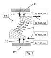
- the suspension spring is removed from the McPherson spring strut 1 and in a spring testing machine 18 measured separately.
- the suspension spring 9 is arranged in the spring testing machine 18 so that the axis of the suspension spring 9 is inclined to the testing machine axis 19 at the same angle as in the installation position in the spring damper leg 1 to the piston rod axis.
- the path s D of the damper piston 11 is thus equal to the stroke in the spring testing machine.
- the horizontal position of the axis 19 of the spring testing machine 18 in the example shown also corresponds to the horizontal position of the axis of the piston rod 12 or the damper tube 10 of the spring damper leg 1.
- the supporting spring 9 is compressed in the testing machine 18 in the direction of the testing machine axis 19, using suitable measuring devices at the ends of the suspension spring 9, the position, the direction and the amount of the resulting force and moment vector 20 of this suspension spring 9 is determined.
- the transverse force F Q, test occurring at the ends of the suspension spring 9 perpendicular to the testing machine axis 19 is determined. From this and from the measured displacement s D, test, the traverse 21 of the spring testing machine 18, ie the spring travel of the suspension spring 9 in the direction of the testing machine axis 19, an F Q / s D spring characteristic test is created, the course of which is at least relevant for comfort Suspension area of the axis is substantially linear.
- the aim is to minimize the frictional forces in the shock absorber leg 1 to the piston rod 12 minimizing attacking lateral forces, d. H. if possible to zero to be brought.
- the construction is designed in such a way that in the main suspension area of the axle the lateral force on the Piston rod guide of the telescopic shock absorber 8 is minimal.
- the F Q / s D spring characteristic curve is installed, is linearized and the difference to the linear F Q / s D spring characteristic curve test is determined.
- this difference is added to the F Q / s D spring characteristic curve test measured in the spring testing machine , is added.
- the transverse force difference even with a single selected damper travel or stroke and therefrom by adding to the Q F / s D -Federkennline testing is a new desired Q F / s D -Federkennline test, to be determined.
- a suspension spring 9 is produced with this new spring characteristic, installed in the spring strut 1 and this in turn installed in the vehicle axle 2. Then, with the new suspension spring 9 - as described above - an F Q / s D spring characteristic curve installation is determined, a determined difference now being between the new F Q / s D spring characteristic curve installation and the predetermined F Q / s D spring characteristic curve installation, should be significantly reduced and may already be within the permissible tolerance range. In the latter case, the optimization of the spring characteristic of the suspension spring 9 is complete. Otherwise, the process described above must be repeated.
- the method according to the invention is based on the knowledge that the F Q / s D spring characteristic installation is dependent, on the one hand, on the suspension spring 9 and, on the other hand, on a large number of parameters, which include the telescopic shock absorber, but which is neither theoretical can still be determined experimentally individually.
- the F Q / s D spring characteristic of the suspension spring 9 can be recorded individually with relatively little effort.
- the F Q / s D spring characteristic of the overall system - as shown in FIG. 1 - is measured and the F Q / s D spring characteristic of the suspension spring 9 is measured and modified by the F Q / s D spring characteristic of the overall system to modify.
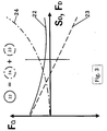
- FIG. 3 shows the individual components of the F Q / s D spring characteristic.
- the solid line represents the resulting F Q / s D spring characteristic curve 22 of the overall system, ie the entire wheel suspension according to FIG. 1.
- This is composed of the F Q / s D spring characteristic curve 23 of the suspension spring 9 shown in dashed lines, which in the Spring testing machine 18 is determined, and from the F Q / s D spring characteristic curve 24, which cannot be determined theoretically or experimentally with reasonable effort, for the rest of the overall system, the time profile of which is shown in broken lines in FIG.
- This representation also applies if the force F D along the direction of the piston rod is used instead of the path S D of the piston rod.
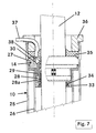
- the measuring element 14 is in the free, second end of the damper tube 10 used.
- the damper tube 10 has in the illustrated Example an outer tube 25 and an inner tube 26, which is arranged in the outer tube 25 and coaxial with this runs.
- the measuring element 14 is made of a solid outer ring 27 which is in the Outer tube 25 of the damper tube 10 is attached centrally, and an inner ring 28 arranged concentrically with the outer ring 27 formed, in which a sliding guide 28a is pressed, the is passed through by the piston rod 12 and on the outer surface is applied.
- Inner ring 28 and outer ring 27 are over one short thin-walled cylindrical tube 29 or one short thin-walled cylindrical wall section with each other connected, which forms the actual measuring body.
- the inner ring 28 extends at a predetermined distance in the axial direction and thus forms one with the wall section 29 circumferential slot 30.
- the transverse force of the piston rod 12 is based on the sliding guide 28a on the inner ring 28 of the measuring element 14. Thereby the inner ring 28 moves relative to the outer ring 27, the thin-walled cylindrical wall portion 29 transversely deformed to the longitudinal axis of the piston rod 12.
- strain gauges a, b; c, d; e, f; g, h are connected together to form a bridge circuit 31, 32.
- These bridge circuits 31, 32 generate signals proportional to the force introduced. Transverse to the respective direction of force, they generate no signal, since such signals from the individual strain gauges cancel each other out in the bridge circuit 31, 32.
- the total lateral force F Q that occurs is recorded as two force components F Qx , F Qy that are perpendicular to one another.
- the measuring element 14 is in the damper tube 10 down by a Sleeve 33 with a high pressure seal 34 and up through a low pressure seal 35 or a dirt scraper included.
- the low pressure seal 35 is in turn by a pressure ring 36 held.
- the pressure ring 36 and the low pressure seal 35 are run through by a cable hose 37 through which the connecting cable 38 of the strain gauges run.
- the measures according to the invention make fine tuning the target configuration and the lateral forces deliberately reduced. This makes the friction in vertical one and one Rebound direction minimal, at least around the intended one Operating point.
- the friction torque when steering is also minimal. This is particularly important when turning the wheels (Articulation) and in the opposite direction to the return of the Wheels in the straight ahead position (steering reset).
Landscapes
- Physics & Mathematics (AREA)
- Mechanical Engineering (AREA)
- Engineering & Computer Science (AREA)
- General Physics & Mathematics (AREA)
- General Health & Medical Sciences (AREA)
- Biochemistry (AREA)
- Analytical Chemistry (AREA)
- Chemical & Material Sciences (AREA)
- Immunology (AREA)
- Pathology (AREA)
- Life Sciences & Earth Sciences (AREA)
- Health & Medical Sciences (AREA)
- Vehicle Body Suspensions (AREA)
- Fluid-Damping Devices (AREA)
- Force Measurement Appropriate To Specific Purposes (AREA)
Abstract
Description
- Figur 1
- in schematischer Darstellung eine Querschnittsansicht durch ein McPherson-Federdämpferbein im in eine Halbachse eingebauten Zustand;
- Figur 2
- in schematischer Darstellung die Tragfeder aus Figur 1, eingebaut in eine Federprüfmaschine;
- Figur 3
- ein Diagramm mit FQ/SD- und FQ/FD-Federkennlinien und - Achskennlinien;
- Figur 4
- eine teilweise geschnittene Seitenansicht eines erfindungsgemäßen Meßgliedes;
- Figur 5
- eine Draufsicht auf das Meßglied aus Figur 4;
- Figur 6
- Schaltbilder der Meßelemente aus Figur 5; und
- Figur 7
- das Meßglied aus Figur 4 und 5 im in ein Dämpferrohr eingebauten Zustand.
Claims (15)
- Verfahren zur Optimierung der Federkennlinie einer Federdämpfereinheit (1) für eine Kraftfahrzeug-Radaufhängung, wobei die Federdämpfereinheit (1) eine Tragfeder (9) und einen diese durchlaufenden Teleskop-Stoßdämpfer (8) aufweist und letzterer seinerseits ein Dämpferrohr (10), dessen erstes Ende mit dem Rad (4) verbindbar ist, einen in dem Dämpferrohr (10) hin- und herbewegbaren Dämpferkolben (11) sowie eine Kolbenstange (12) aufweist, deren erstes Ende am Dämpferkolben (11) befestigt ist und die im Dämpferrohr (10) durch ein Kolbenstangenführungselement (14) geführt ist, sich aus dem zweiten Ende des Dämpferrohrs (10) heraus erstreckt und die an ihrem zweiten Ende mit dem Fahrzeugaufbau (6) gelenkig verbindbar ist, wobei ein Ende der Tragfeder (9) am Dämpferrohr (10) und deren anderes Ende nahe dem zweiten Ende der Kolbenstange (12) unverschieblich befestigt ist, mit den folgenden Schritten:a) Einbauen der Federdämpfereinheit (1) in eine Fahrzeugachse (2);b) Einfedern des Rades (4) und dabei Messen der auf das Kolbenstangenführungselement (14) wirkenden Querkraft FQ,Einbau,ist und des zugehörigen Dämpfereinschubweges sD,Einbau,ist und Erstellen einer entsprechenden FQ/sD-FederkennlinieEinbau,ist;c) falls die FQ/sD-FederkennlinieEinbau,ist von einer FQ/sD-FederkennlinieEinbau,soll um ein vorgegebenes Maß abweicht, Ausbauen der Tragfeder (9) aus der Federdämpfereinheit (1);d) Anordnen der Tragfeder (9) in einer Federprüfmaschine (18) derart, daß die Achse der Tragfeder (9) zur Prüfmaschinenachse (19) in demselben Winkel geneigt ist wie in der Einbaulage in der Federdämpfereinheit (1) zur Kolbenstangenachse;e) Messen des Federweges sD,Prüf,ist der Tragfeder (9) in Richtung der Prüfmaschinenachse (19) und Ermitteln der zugehörigen Querkraft FQ,Prüf,ist quer zur Prüfmaschinenachse (19) und Erstellen einer entsprechenden FQ/sD-FederkennliniePrüf,ist;f) Bestimmen einer FQ/sD-FederkennliniePrüf, soll durch Überlagern der FQ/sD-FederkennliniePrüf, ist mit der FQ/sD-FederkennlinieEinbau,ist;g) Herstellen einer neuen Tragfeder (9), die die neue FQ/sD-FederkennliniePrüf, soll aufweist;h) Wiederholen der Schritte a) und b) und gegebenenfalls c) bis g).
- Verfahren nach Anspruch 1,
dadurch gekennzeichnet, daß der Schritt b) das Anordnen des Kolbenstangenführungselements (14) nahe dem zweiten Ende des Dämpferrohres (10) umfasst. - Verfahren nach Anspruch 1 oder 2,
dadurch gekennzeichnet, dass die Tragfeder (9) in der Federprüfmaschine (18) so angeordnet wird, dass die Lage der Prüfmaschinenachse (19) in Bezug auf die Tragfeder (9) der Lage der Kolbenstangenachse entspricht. - Verfahren nach einem der Ansprüche 1 bis 3,
dadurch gekennzeichnet, daß das Ermitteln der Querkraft FQ,Prüf,ist das Ermitteln der Lage, der Richtung und des Betrags des resultierenden Kraftund Momentenvektors (20) der Tragfeder (9) umfasst. - Verfahren nach Anspruch 4,
dadurch gekennzeichnet, dass der resultierende Kraft- und Momentenvektor (20) durch Messungen an einem der Enden oder an beiden Enden der Tragfeder (9) ermittelt wird. - Verfahren nach einem der Ansprüche 1 bis 5,
dadurch gekennzeichnet, dass die FQ/sD-FederkennliniePrüf,soll bestimmt wird, indem bei einem ausgewählten Wert sD die Differenz zwischen dem Wert FQ,Einbau,ist und einem gewünschten Wert FQ,Einbau,soll ermittelt und zu dem Wert FQ,Prüf,ist addiert wird. - Verfahren nach einem der Ansprüche 1 bis 5,
dadurch gekennzeichnet, daß die FQ/sD-FederkennliniePrüf,soll bestimmt wird, indem die FQ/sD-FederkennlinieEinbau,ist in einem vorgegebenen sD-Bereich linearisiert wird und die Differenz zu einer vorgegebenen linearen FQ/sD-FederkennlinieEinbau,soll in diesem sD-Bereich gebildet und zu der FQ/sD-FederkennliniePrüf,ist addiert wird. - Verfahren nach einem der Ansprüche 1 bis 7,
dadurch gekennzeichnet, daß die FQ/sD-FederkennliniePrüf,soll so bestimmt wird, daß FQ,Einbau,ist minimiert wird. - Meßglied zur Messung der in einer Zylinderkolbeneinheit, insbesondere in einem Teleskop-Stoßdämpfer, vorhandenen Querkraft, wobei die Zylinderkolbeneinheit ein Zylinderrohr (10; 25, 26), einen in dem Zylinderrohr (10; 25, 26) hin- und herbewegbaren Kolben (11) und eine Kolbenstange (12) aufweist, die an dem Kolben (11) befestigt ist und sich in Längsrichtung des Zylinderrohrs (10; 25, 26) erstreckt,
dadurch gekennzeichnet, daß das Meßglied (14) als Rohrabschnitt ausgebildet ist, der von der Kolbenstange (12) durchlaufen werden kann, der in dem Zylinderrohr (10; 25, 26) befestigbar ist und der in Radialrichtung eine Innenwandung sowie eine Außenwandung aufweist, daß die Innenwandung zur vollumfänglichen gleitenden Anlage an die Kolbenstange (12) ausgebildet ist und daß die Außenwandung wenigstens einen Wandungsabschnitt (29) aufweist, der im in das Zylinderrohr (10; 25, 26) eingesetzten Zustand von dessen Innenwandung mit Abstand angeordnet ist und auf dem Meßelemente (a, b; c, d; e, f; g, h) zur Messung der Querkraft angebracht sind. - Meßglied nach Anspruch 9,
dadurch gekennzeichnet, daß die Meßelemente Dehnungsmeßstreifen (a, b; c, d; e, f; g, h) sind. - Meßglied nach Anspruch 9 oder 10,
dadurch gekennzeichnet, daß auf der Innenwandung des Rohrabschnitts Gleitmaterial (28a) angebracht ist. - Meßglied nach einem der Ansprüche 9 bis 11,
dadurch gekennzeichnet, daß der Rohrabschnitt zwischen seiner Innenwandung und seiner Außenwandung einen in Umfangsrichtung vollständig umlaufenden Schlitz (30) aufweist, der sich in Längsrichtung von einem Ende des Rohrabschnitts aus über die Messelemente (a, b; c, d; e, f; g, h) hinaus bis zu einem vorgegebenen Abstand vom anderen Ende des Rohrabschnitts erstreckt. - Meßglied nach einem der Ansprüche 9 bis 12,
dadurch gekennzeichnet, daß der Rohrabschnitt mit einem Befestigungselement am Zylinderrohr befestigt ist, wobei das Befestigungselement sich von einem Ende des Rohrabschnitts aus erstreckt. - Meßglied nach einem der Ansprüche 9 bis 13,
dadurch gekennzeichnet, daß es je Meßrichtung zwei Meßelemente aufweist, die am Umfang versetzt zueinander angeordnet sind. - Meßglied nach einem der Ansprüche 9 bis 14,
dadurch gekennzeichnet, daß es einen Außenring (27), der im Zylinderrohr (10; 25, 26) koaxial zur Zylinderachse befestigbar ist, einen Innenring (28), der zum Außenring (27) konzentrisch angeordnet und zur gleitenden Anlage an die Kolbenstange (12) ausgebildet ist, sowie einen dünnwandigen zylindrischen Wandabschnitt (29) aufweist, der in Längsrichtung des Zylinderrohrs (10; 25, 26) zwischen Außenring (27) und Innenring (28) angeordnet ist und diese miteinander verbindet und auf dessen radialer Außenwandung die Meßelemente (a, b; c, d; e, f; g, h) angebracht sind.
Applications Claiming Priority (2)
| Application Number | Priority Date | Filing Date | Title |
|---|---|---|---|
| DE10238788 | 2002-08-23 | ||
| DE2002138788 DE10238788B4 (de) | 2002-08-23 | 2002-08-23 | Optimierung der Federkennlinie einer Federdämpfereinheit für eine Kraftfahrzeug-Radaufhängung |
Publications (2)
| Publication Number | Publication Date |
|---|---|
| EP1393937A2 true EP1393937A2 (de) | 2004-03-03 |
| EP1393937A3 EP1393937A3 (de) | 2004-12-01 |
Family
ID=31197302
Family Applications (1)
| Application Number | Title | Priority Date | Filing Date |
|---|---|---|---|
| EP03018836A Withdrawn EP1393937A3 (de) | 2002-08-23 | 2003-08-19 | Optimierung der Federkennlinie einer Federdämpfereinheit für eine Kraftfahrzeug-Radaufhängung |
Country Status (2)
| Country | Link |
|---|---|
| EP (1) | EP1393937A3 (de) |
| DE (1) | DE10238788B4 (de) |
Cited By (3)
| Publication number | Priority date | Publication date | Assignee | Title |
|---|---|---|---|---|
| DE102011109713A1 (de) | 2011-08-06 | 2013-02-07 | Audi Ag | Federbein für eine Kraftfahrzeug-Radaufhängung |
| DE102014226225B4 (de) * | 2014-12-17 | 2020-08-27 | Zf Friedrichshafen Ag | Radaufhängungsanordnung |
| CZ310309B6 (cs) * | 2018-09-27 | 2025-02-12 | VÚTS, a.s., Liberec | Měřicí vodítko pro měření radiální komponenty kontaktní síly mezi pístní tyčí a vedením pístní tyče v tlumiči kolového vozidla |
Families Citing this family (3)
| Publication number | Priority date | Publication date | Assignee | Title |
|---|---|---|---|---|
| DE102011102902A1 (de) | 2011-05-31 | 2012-12-06 | GM Global Technology Operations LLC (n. d. Gesetzen des Staates Delaware) | Verfahren zum Kalibrieren eines adaptiven Fahrwerksystems |
| CN114112149B (zh) * | 2021-12-10 | 2023-05-12 | 中国船舶科学研究中心 | 一种运动物体接触载荷的测量装置及测量方法 |
| JP2023166819A (ja) * | 2022-05-10 | 2023-11-22 | ミネベアミツミ株式会社 | 軸受装置、ひずみ検出装置 |
Family Cites Families (3)
| Publication number | Priority date | Publication date | Assignee | Title |
|---|---|---|---|---|
| JPS62286816A (ja) * | 1986-06-03 | 1987-12-12 | Nissan Motor Co Ltd | サスペンシヨン荷重検出装置 |
| DE69627116T2 (de) * | 1995-12-19 | 2003-12-24 | Compagnie Generale Des Etablissements Michelin-Michelin & Cie., Clermont-Ferrand | Feineinstellung eines MacPherson-Federbeines: Vorrichtung zur Einstellung auf dem Federbein und Bank zum Messen |
| US5979218A (en) * | 1997-11-12 | 1999-11-09 | Chrysler Corporation | Strut mount transducer |
-
2002
- 2002-08-23 DE DE2002138788 patent/DE10238788B4/de not_active Expired - Lifetime
-
2003
- 2003-08-19 EP EP03018836A patent/EP1393937A3/de not_active Withdrawn
Non-Patent Citations (3)
| Title |
|---|
| "Allevard Ressorts", 1997, article HASTEY J.P. /BAUDELET,J./GERARD, E./JONES, C./VIEL: "C.: Optimization on Macpherson Suspensions with a Spring,", pages: 119 - 124, 970100 |
| Aufsätze von Wünsche, T./Muhr, K.-H./Biecker, K./Schnaubelt, L.: Side Load Springs as a Solution to Minimize Adverse Side Loads Acting on the McPherson Strut, 940862, SAE SP-1031, S. 11-16 |
| Niepage, P./Müller, H.: ein hybrides Verfahren zur Untersuchung beliebig beanspruchter Schraubendruckfedern ohne Windungsberührung, Draht 37 (1986) 8, S. 457-461 |
Cited By (4)
| Publication number | Priority date | Publication date | Assignee | Title |
|---|---|---|---|---|
| DE102011109713A1 (de) | 2011-08-06 | 2013-02-07 | Audi Ag | Federbein für eine Kraftfahrzeug-Radaufhängung |
| DE102011109713B4 (de) | 2011-08-06 | 2018-03-29 | Audi Ag | Federbein für eine Kraftfahrzeug-Radaufhängung |
| DE102014226225B4 (de) * | 2014-12-17 | 2020-08-27 | Zf Friedrichshafen Ag | Radaufhängungsanordnung |
| CZ310309B6 (cs) * | 2018-09-27 | 2025-02-12 | VÚTS, a.s., Liberec | Měřicí vodítko pro měření radiální komponenty kontaktní síly mezi pístní tyčí a vedením pístní tyče v tlumiči kolového vozidla |
Also Published As
| Publication number | Publication date |
|---|---|
| EP1393937A3 (de) | 2004-12-01 |
| DE10238788A1 (de) | 2004-03-18 |
| DE10238788B4 (de) | 2004-07-29 |
Similar Documents
| Publication | Publication Date | Title |
|---|---|---|
| DE4231641C2 (de) | Federbein für Federungssysteme von Kraftfahrzeugen | |
| DE3823764C2 (de) | Prüfstand zum Prüfen eines Achsenaufbaus eines Nutzfahrzeugs | |
| DE102016001594B3 (de) | Fahrwerksystem für ein Kraftfahrzeug, Kraftfahrzeug | |
| DE3736284C2 (de) | ||
| DE3025478A1 (de) | Belastungstestanlage fuer fahrzeugachsen | |
| DE3943007A1 (de) | Regelanlage fuer die unterdrueckung von rollbewegungen bei einem kraftfahrzeug | |
| DE3935755A1 (de) | Aufhaengesystem fuer kraftfahrzeuge | |
| EP3521791A1 (de) | Lenkungsprüfstand | |
| DE19815197C1 (de) | Schienenfahrzeug mit einem verikalen Stützaktuator | |
| DE2016540C3 (de) | Federung für Kraftfahrzeuge mit Niveauregelung | |
| DE10238788B4 (de) | Optimierung der Federkennlinie einer Federdämpfereinheit für eine Kraftfahrzeug-Radaufhängung | |
| DE19606990A1 (de) | Teleskopartiger Schwingungsdämpfer zwischen dem Aufbau und dem Führungselement eines Rades eines Kraftfahrzeuges | |
| DE3912043C2 (de) | ||
| DE4215852C2 (de) | Einrichtung zum Prüfen eines mindestens ein Federelement umfassenden Bauteils | |
| DE4313973C2 (de) | Aktive Federung einer Masse, insbesondere Fahrerhausfederung eines Nutzfahrzeuges | |
| DD141769A1 (de) | Schwingungsgeminderte fahrerkabine fuer selbstfahrende arbeitsmaschinen | |
| WO2017137189A1 (de) | Schwingungsdämpferanordnung sowie kraftfahrzeug | |
| DE19958178C1 (de) | Feder-Dämpfer-Bein | |
| DE3841771A1 (de) | Rad- bzw. achsabstuetzaggregat | |
| EP1403103B1 (de) | Verstellbares Federbein für Kraftfahrzeuge | |
| DE19651162A1 (de) | Schwingungsdämpfer für eine Überwachungseinrichtung von der Fahrsicherheit dienenden Größen | |
| DE19840619C1 (de) | Passive Wankdämpfung mit mindestens einem Dämpfer pro Fahrzeugachse | |
| DE3934896C2 (de) | Endanschlagdämpfer zur Dämpfung einer in ein Fahrzeugrad eingeleiteten Stoßenergie | |
| EP0450576B1 (de) | Karosserieseitige Lagerung eines Federbeins sowie Verfahren zur Herstellung einer solchen Lagerung | |
| DE102018000149A1 (de) | Kraftfahrzeug |
Legal Events
| Date | Code | Title | Description |
|---|---|---|---|
| PUAI | Public reference made under article 153(3) epc to a published international application that has entered the european phase |
Free format text: ORIGINAL CODE: 0009012 |
|
| AK | Designated contracting states |
Kind code of ref document: A2 Designated state(s): AT BE BG CH CY CZ DE DK EE ES FI FR GB GR HU IE IT LI LU MC NL PT RO SE SI SK TR |
|
| AX | Request for extension of the european patent |
Extension state: AL LT LV MK |
|
| PUAL | Search report despatched |
Free format text: ORIGINAL CODE: 0009013 |
|
| AK | Designated contracting states |
Kind code of ref document: A3 Designated state(s): AT BE BG CH CY CZ DE DK EE ES FI FR GB GR HU IE IT LI LU MC NL PT RO SE SI SK TR |
|
| AX | Request for extension of the european patent |
Extension state: AL LT LV MK |
|
| 17P | Request for examination filed |
Effective date: 20050530 |
|
| AKX | Designation fees paid |
Designated state(s): AT BE BG CH CY CZ DE DK EE ES FI FR GB GR HU IE IT LI LU MC NL PT RO SE SI SK TR |
|
| STAA | Information on the status of an ep patent application or granted ep patent |
Free format text: STATUS: THE APPLICATION IS DEEMED TO BE WITHDRAWN |
|
| 18D | Application deemed to be withdrawn |
Effective date: 20070306 |