EP1391357A2 - Gurtvorrichtung - Google Patents
Gurtvorrichtung Download PDFInfo
- Publication number
- EP1391357A2 EP1391357A2 EP03090214A EP03090214A EP1391357A2 EP 1391357 A2 EP1391357 A2 EP 1391357A2 EP 03090214 A EP03090214 A EP 03090214A EP 03090214 A EP03090214 A EP 03090214A EP 1391357 A2 EP1391357 A2 EP 1391357A2
- Authority
- EP
- European Patent Office
- Prior art keywords
- belt
- guide pin
- locking
- reel
- belt reel
- Prior art date
- Legal status (The legal status is an assumption and is not a legal conclusion. Google has not performed a legal analysis and makes no representation as to the accuracy of the status listed.)
- Granted
Links
Images


Classifications
-
- B—PERFORMING OPERATIONS; TRANSPORTING
- B60—VEHICLES IN GENERAL
- B60R—VEHICLES, VEHICLE FITTINGS, OR VEHICLE PARTS, NOT OTHERWISE PROVIDED FOR
- B60R22/00—Safety belts or body harnesses in vehicles
- B60R22/34—Belt retractors, e.g. reels
- B60R22/36—Belt retractors, e.g. reels self-locking in an emergency
- B60R22/41—Belt retractors, e.g. reels self-locking in an emergency with additional means for preventing locking during unwinding under predetermined conditions
-
- B—PERFORMING OPERATIONS; TRANSPORTING
- B60—VEHICLES IN GENERAL
- B60R—VEHICLES, VEHICLE FITTINGS, OR VEHICLE PARTS, NOT OTHERWISE PROVIDED FOR
- B60R22/00—Safety belts or body harnesses in vehicles
- B60R22/34—Belt retractors, e.g. reels
- B60R22/36—Belt retractors, e.g. reels self-locking in an emergency
- B60R22/38—Belt retractors, e.g. reels self-locking in an emergency responsive only to belt movement
-
- B—PERFORMING OPERATIONS; TRANSPORTING
- B60—VEHICLES IN GENERAL
- B60R—VEHICLES, VEHICLE FITTINGS, OR VEHICLE PARTS, NOT OTHERWISE PROVIDED FOR
- B60R22/00—Safety belts or body harnesses in vehicles
- B60R22/34—Belt retractors, e.g. reels
- B60R22/36—Belt retractors, e.g. reels self-locking in an emergency
- B60R22/405—Belt retractors, e.g. reels self-locking in an emergency responsive to belt movement and vehicle movement
-
- B—PERFORMING OPERATIONS; TRANSPORTING
- B60—VEHICLES IN GENERAL
- B60R—VEHICLES, VEHICLE FITTINGS, OR VEHICLE PARTS, NOT OTHERWISE PROVIDED FOR
- B60R22/00—Safety belts or body harnesses in vehicles
- B60R22/34—Belt retractors, e.g. reels
- B60R2022/3419—Belt retractors, e.g. reels with end lock preventing means
Definitions
- the invention relates to a belt device.
- Known belt devices have belt locks, with the help of which the belt is locked in the event of a jerky unrolling.
- Such Belt locks have a locking element that one jerky unrolling of the belt with the frame of the belt device locked.
- the belt devices often have a high Noise development.
- the object of the present invention is to address these problems to accept. This task is carried out by the independent Claims specified invention solved. advantageous Embodiments of the invention are in the subclaims remove.
- a belt device for a vehicle created with: a seat belt; one on the vehicle chassis rotatably attached belt reel for rolling up and unrolling the safety belt; a first locking device for locking the belt reel against a belt frame; and one to the Locking device coupled guide pin which within a Leadership backdrop between a first and a second position is movably guided, the belt reel in the first position is locked against the belt frame, and in the second Position a locking of the belt reel against the belt frame is prevented.
- the guide pin becomes dependent on the direction of rotation the belt reel is moved to the first or the second position. In order to can already cause an unwanted blocking by means of the direction of rotation the belt reel can be prevented.
- the Guide pin when unrolling the belt in the first and at The belt is moved to the second position.
- the guide link can have a lost motion, in which the introductory grantt occupies said second position. When ingested this position becomes a change of state of the first Locking device generally prevented.
- the guide link can be perpendicular to the axis of rotation of the belt reel run. By arranging the guide link perpendicular to the The axis of rotation can arise from the rotation of the belt reel Centrifugal forces optimal for transferring the guide pin into the second position can be used.
- the guiding backdrop can consist of a longer and a longer one in addition, essentially vertical, shorter backdrop section exist, the first position being at the junction of the two sections opposite end of the longer one Section, and the second position is at the junction of the two sections opposite end of the shorter one Section.
- the longer backdrop section thus serves to transfer the guide pin to the first position and to lock the belt reel.
- the shorter one Link section serves to transfer the guide pin into the second position, in which the belt reel cannot be locked becomes. The forces required for this arise in both cases Rotation of the belt reel.
- the belt device preferably also has a spring element on that the first locking device and the coupled Holds guide pin in a rest position. This will ensures that the guide pin after the Belt roll not at one of the ends of the link sections persists, but immediately to the rest position in the area of Junction of the two backdrop sections returns. This ensures reliable operation even when repeated jerky winding or unrolling of the belt at short intervals.
- the spring element can be a coil spring or a bow spring be educated.
- the first locking device can have a pawl that to lock the belt reel with a frame of Belt device can be locked.
- the belt reel can have the following additional features have: one with the belt reel and the first locking device connected flange; a rotatably attached to the vehicle chassis Ratchet wheel; and a second locking device coupled to the ratchet wheel Locking the ratchet wheel in the event of a jerky rolling of the safety belt; the guide link in the ratchet wheel is provided, and the guide pin when the Ratchet wheel by further rotation of the flange and the first Locking device along the guide link in the direction of first position is moved, thereby locking the Belt roll is triggered by the first locking device, and the guide pin by jerkily rolling up the Seat belt is moved towards the second position whereby the belt reel is locked by the first Locking device is prevented.
- the second locking device can be formed by a pawl be when a predetermined value is exceeded Angular acceleration of the belt reel in a belt unwinding direction Interlocking of a wheel rim engages, causing the ratchet wheel locked against the belt reel, and with further rotation the belt roller opposite the ratchet wheel the guide pin inside the guide link is moved to the first position.
- the belt device has rotatable relative to the belt reel about the belt reel axis Inertial mass element, with the guide link in the Inertial mass element is provided, being exceeded a predetermined angular acceleration of the belt reel Inertial mass element rotated relative to the belt reel and the Guide pin in the guide link from the first to the second Position is moved.
- This configuration has the advantage of being reduced Parts requirements, so that manufacturing effort and costs are reduced are.
- FIGS 7 and 8 schematically parts of a belt device according to a second embodiment of the invention.
- Figure 9 schematically shows parts of a belt device according to a third Embodiment of the invention.
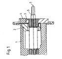
- Figure 1 shows schematically the cross section of a force limiter for a belt system.
- Figure 2 shows the individual parts of the limiter in perspective view.
- the force limiter includes one rotatable spindle 1 with a spindle bearing 2 on which a not shown holding belt can be rolled up and unrolled.
- a relative to Spindle 1 rotatable flange 3 arranged.
- Pawl 4 for locking the flange against one Belt frame provided, for example in a jerky Taking off the belt.
- a torsion or torsion bar 5 is provided, which both ends has a ring gear, by means of which the torsion bar 5 in corresponding recesses of the spindle 1 or the flange 3 is anchored against rotation.
- the torsion bar 5 couples the spindle 1 and the flange 3 with each other, so that when the Limiter (i.e. in the absence of an accident) spindle 1 and the flange 3 can rotate together about an axis of rotation 7 roll up the belt on or off the spindle 1.
- Figure 3 shows schematically a perspective view of a Ratchet wheel 10 and a rim 11 of a belt device a first embodiment of the invention. Like the arrows indicated the wheel rim 11 is placed on the ratchet wheel 10. Alternatively, the ratchet wheel 10 can also be placed on the wheel rim 11 put on.
- the wheel rim 11 is locked to the belt frame while the ratchet wheel 10 is rotatable relative to the belt frame.
- the inner circumferential surface of the wheel rim 11 has teeth 12 provided with which a second pawl 13 latches when for example, the belt is pulled out jerkily.
- This is the Pawl 13 around a on the base of the ratchet wheel 10th arranged axis 14 rotatably mounted.
- the axis 14 lies outside the center of the circular base of the Locking wheel 10. If the belt pulls out suddenly, it turns the pawl 13 against the spring force of a spring 15 to the Axis 14 around, so that the tip 16 of the pawl 13 with the Teeth 12 of the wheel rim 11 locked.
- the ratchet wheel 10 is with the flange 3 via a not shown Tension spring connected. In normal operation, the ratchet wheel 10 rotates at the same speed as the flange 3. The torque is transmitted through the tension spring. If the belt jerky pulled out, the second pawl 13 rotates about Axis 14 around and locked with the teeth 12 of the wheel rim 11, as described above. The ratchet wheel connected to the rim 11 10 is thus locked against the belt frame. The flange 3 with the first pawl 4 now turns against Spring force of the tension spring together with the spindle 1 continues.
- the first pawl is 20 in by means of a guide pin a guide link 18 in the ratchet wheel 10.
- This Leadership does nothing as long as the ratchet wheel 10 is together with which rotates the flange 3.
- the ratchet wheel 10 is like locked to the belt frame as described, then the Flange 3 together with the first pawl 4 opposite Ratchet wheel 10 further.
- the first pawl 4 consequently rotates relative to the ratchet wheel 10, the orientation of the first Pawl 4 during this relative rotation now through the Guide link 18 is determined.
- This leads to the first Pawl 4 engages with the frame of the belt device is brought and thus a further roatation of the flange 3 and the associated spindle 1 blocked.
- the belt lock is therefore active.
- FIG. 4 schematically shows a front view of the ratchet wheel 10 with pawl 13 placed on axis 14
- Arrow 17 is again indicated here how the tip 16 of the Pawl 13 moves outward when a by rotating the Torch caused torque acts on the pawl 13, that is greater than that due to the retention force of the spring 15 generated torque.
- FIG 4 shows the guide pin 20 in its rest position.
- the first Pawl 4 and thus the one with the first pawl 4 connected guide pin 18 are by a not shown Spring element held in the rest position.
- FIG. 5 also shows schematically a frontal view of the Ratchet wheel 10, here the guide pin 20 on a radial external stop 21 of the guide link 18 is present.
- the Moving the guide pin 20 along the backdrop 18 is caused by blocking the ratchet wheel 10 relative to the flange 3, as described above. Due to the relative rotation of the flange 3 together with the first pawl 4 is the one with the first Pawl 4 connected guide pin 20 along the Guide link 18 moved relative to the ratchet wheel 10 until the first pawl 4 locked to the frame of the belt device and activated the belt lock.
- Figures 7 and 8 each show part of a Belt device according to a second embodiment of the invention.
- an inertial mass 25 in the form of a disc provided which is rotatably mounted on the spindle axis 26 and by a prestressed spring element 27 indirectly in its rest position is held.
- the spring element is on the one hand with the Spindle axis 26 and on the other hand with the guide pin 20th coupled.
- the guide pin 20 is the same as in the first embodiment coupled with the first pawl 4 and in one Guide link 18 guided in the inertial mass 25.
- the spring element 27 is designed so that its spring force to the first pawl 4 at a defined angular acceleration and holds the inertial mass 25 in the rest position. At the If the acceleration threshold is exceeded, a Relative movement between the spindle 1 and the inertial mass 25 on. As a result, the guide pin 20 is in the guide link 18 moved and the first pawl 4 in the belt frame be controlled.
- This configuration has the advantage that the number of required individual parts and thus the costs can be reduced. There are also short entry routes and times until Locking the spindle 1. In addition, the Noise of the first pawl 4 reduced.
- Figure 9 shows a belt device according to another Embodiment of the invention.
- the Guide pin 20 by means of a bow spring 30 in the shown Rest position held within the guide link 18.
- the Bow spring 30 prevents free movement of the guide pin and thus the first pawl 4, so that next to one unwanted locking of the spindle 1 also an unwanted Rattling of the pawl 4 or the guide pin 20 prevented becomes.
Landscapes
- Engineering & Computer Science (AREA)
- Mechanical Engineering (AREA)
- Automotive Seat Belt Assembly (AREA)
Abstract
Description
- 1
- Spindel
- 2
- Spindellager
- 3
- Flansch
- 4
- erste Sperrklinke
- 5
- Drehstab
- 7
- Drehachse
- 10
- Sperrrad
- 11
- Radkranz
- 12
- Zähne
- 13
- zweite Sperrklinke
- 14
- Achse
- 15
- Feder
- 16
- Spitze der zweiten Sperrklinke
- 17
- Drehrichtung der zweiten Sperrklinke
- 18
- Führungskulisse
- 20
- Führungsstift
- 21
- Anschlag
- 22
- Totgang
- 25
- Trägheitsmasse
- 26
- Spindelachse
- 27
- Spiralfeder
- 30
- Bügelfeder
Claims (14)
- Gurtvorrichtung für ein Fahrzeug, mit:einem Sicherheitsgurt;einer am Fahrzeugchassis drehbar befestigten Gurtrolle zum Aufund Abrollen des Sicherheitsgurtes;einer ersten Sperrvorrichtung zur Verriegelung der Gurtrolle gegenüber einem Gurtrahmen; undeinem an die Sperrvorrichtung gekoppelten Führungsstift, der innerhalb einer Führungskulisse zwischen einer ersten und einer zweiten Position beweglich geführt ist, wobei in der ersten Position die Gurtrolle gegenüber dem Gurtrahmen verriegelt ist, und in der zweiten Position eine Verriegelung der Gurtrolle gegenüber dem Gurtrahmen verhindert ist.
- Gurtvorrichtung nach Anspruch 1, wobei der Führungsstift abhängig von der Drehrichtung der Gurtrolle in die erste oder die zweite Position bewegt wird.
- Gurtvorrichtung nach Anspruch 2, wobei der Führungsstift bei Abrollen des Gurtes in die erste und bei Aufrollen des Gurtes in die zweite Position bewegt wird.
- Gurtvorrichtung nach einem der vorhergehenden Ansprüche, wobei eine Bewegung des Führungsstiftes in die zweite Position durch die bei der Drehung der Gurtrolle entstehenden Trägheitsmomente der ersten Sperrvorrichtung und/oder des Führungselementes bewirkt wird.
- Gurtvorrichtung nach einem der vorhergehenden Ansprüche, wobei die Führungskulisse einen Totgang aufweist, in welchem der Führungsstift besagte zweite Position einnimmt.
- Gurtvorrichtung nach einem der vorhergehenden Ansprüche, wobei die Führungskulisse senkrecht zur Drehachse der Gurtrolle verläuft.
- Gurtvorrichtung nach einem der vorhergehenden Ansprüche, wobei die Führungskulisse aus einem längeren und einem dazu im wesentlichen senkrechten kürzeren Kulissenabschnitt besteht, und wobei die erste Position sich am der Verbindungsstelle der beiden Abschnitte entgegengesetzten Ende des längeren Abschnittes, und die zweite Position sich am der Verbindungsstelle der beiden Abschnitte entgegengesetzten Ende des kürzeren Abschnittes befindet.
- Gurtvorrichtung nach einem der vorhergehenden Ansprüche, mit einem Federelement, das die erste Sperrvorrichtung und den angekoppelten Führungsstift in einer Ruheposition hält.
- Gurtvorrichtung nach Anspruch 8, wobei das Federelement durch eine Spiralfeder gebildet ist.
- Gurtvorrichtung nach Anspruch 8, wobei das Federelement durch eine Bügelfeder gebildet ist.
- Gurtvorrichtung nach einem der vorhergehenden Ansprüche, wobei die erste Sperrvorrichtung eine Sperrklinke aufweist, die zur Verriegelung der Gurtrolle mit einem Rahmen der Gurtvorrichtung verrastbar ist.
- Gurtvorrichtung nach Anspruch 1, mit:wobei die Führungskulisse in dem Sperrrad vorgesehen ist, und der Führungsstift bei Verriegelung des Sperrrades durch weitere Drehung des Flansches und der ersten Sperrvorrichtung entlang der Führungskulisse in Richtung der ersten Position bewegt wird, wodurch eine Verriegelung der Gurtrolle durch die erste Sperrvorrichtung ausgelöst wird, und wobei der Führungsstift durch ruckartiges Aufrollen des Sicherheitsgurtes in Richtung der zweiten Position bewegt wird, wodurch eine Verriegelung der Gurtrolle durch die erste Sperrvorrichtung verhindert wird.einem mit der Gurtrolle und der ersten Sperrvorrichtung verbundenen Flansch;einem drehbar am Fahrzeugchassis befestigten Sperrrad; undeiner an das Sperrrad gekoppelten zweiten Sperrvorrichtung zur Verriegelung des Sperrrades bei einem ruckartigen Abrollen des Sicherheitsgurtes;
- Gurtvorrichtung nach Anspruch 12, wobei die zweite Sperrvorrichtung durch eine Sperrklinke gebildet ist, die bei Überschreiten einer vorbestimmten Winkelbeschleunigung der Gurtrolle in Gurtabrollrichtung in eine Verzahnung eines Radkranzes eingreift, wodurch das Sperrrad gegenüber der Gurtrolle verriegelt wird, und bei weiterer Rotation der Gurtrolle gegenüber dem Sperrrad der Führungsstift innerhalb der Führungskulisse in die erste Position bewegt wird.
- Gurtvorrichtung nach Anspruch 1, mit:einem relativ zu der Gurtrolle um die Gurtrollenachse drehbaren Trägheitsmassenelement, wobei die Führungskulisse in dem Trägheitsmassenelement vorgesehen ist, wobei bei Überschreiten einer vorbestimmten Winkelbeschleunigung der Gurtrolle das Trägheitsmassenelement gegenüber der Gurtrolle verdreht und der Führungsstift in der Führungskulisse von der ersten in die zweite Position bewegt wird.
Applications Claiming Priority (2)
| Application Number | Priority Date | Filing Date | Title |
|---|---|---|---|
| DE10236858A DE10236858B4 (de) | 2002-08-07 | 2002-08-07 | Gurtvorrichtung |
| DE10236858 | 2002-08-07 |
Publications (3)
| Publication Number | Publication Date |
|---|---|
| EP1391357A2 true EP1391357A2 (de) | 2004-02-25 |
| EP1391357A3 EP1391357A3 (de) | 2004-03-31 |
| EP1391357B1 EP1391357B1 (de) | 2006-12-13 |
Family
ID=30775166
Family Applications (1)
| Application Number | Title | Priority Date | Filing Date |
|---|---|---|---|
| EP03090214A Expired - Lifetime EP1391357B1 (de) | 2002-08-07 | 2003-07-15 | Gurtvorrichtung |
Country Status (5)
| Country | Link |
|---|---|
| US (1) | US6902129B2 (de) |
| EP (1) | EP1391357B1 (de) |
| JP (1) | JP4414174B2 (de) |
| CN (1) | CN1325309C (de) |
| DE (2) | DE10236858B4 (de) |
Cited By (3)
| Publication number | Priority date | Publication date | Assignee | Title |
|---|---|---|---|---|
| WO2009049754A1 (de) * | 2007-10-10 | 2009-04-23 | Autoliv Development Ab | Selbstsperrender gurtaufroller |
| WO2009143984A1 (de) * | 2008-05-27 | 2009-12-03 | Autoliv Development Ab | Sicherheitsgurtaufroller mit sensorabschaltung |
| CN102259632A (zh) * | 2010-05-27 | 2011-11-30 | 株式会社东海理化电机制作所 | 安全带卷绕装置及旋转检测部件的制造方法 |
Families Citing this family (7)
| Publication number | Priority date | Publication date | Assignee | Title |
|---|---|---|---|---|
| JP2005289320A (ja) * | 2004-04-05 | 2005-10-20 | Tokai Rika Co Ltd | ウエビング巻取装置 |
| JP4914201B2 (ja) * | 2006-06-20 | 2012-04-11 | 株式会社東海理化電機製作所 | ウエビング巻取装置 |
| JP4917395B2 (ja) * | 2006-09-19 | 2012-04-18 | 株式会社東海理化電機製作所 | ウエビング巻取装置 |
| JP4976241B2 (ja) * | 2007-09-04 | 2012-07-18 | タカタ株式会社 | シートベルトリトラクタおよびこれを用いたシートベルト装置 |
| JPWO2009107672A1 (ja) * | 2008-02-25 | 2011-07-07 | 学校法人東海大学 | ロボット安全装置、及びロボット |
| CN104554135B (zh) * | 2013-10-09 | 2017-06-06 | 比亚迪股份有限公司 | 安全带卷收器及具有其的安全带装置和汽车 |
| CN107128279B (zh) * | 2017-06-21 | 2023-07-21 | 重庆光大产业有限公司 | 卷收器 |
Family Cites Families (16)
| Publication number | Priority date | Publication date | Assignee | Title |
|---|---|---|---|---|
| DE2423398A1 (de) * | 1974-05-14 | 1975-11-27 | Audi Nsu Auto Union Ag | Abrollsperre fuer sicherheitsgurte in kraftfahrzeugen |
| DE2722744A1 (de) * | 1977-05-20 | 1978-11-23 | Eckhard Dr Ing Hildebrandt | Aufrollvorrichtung fuer sicherheitsgurte von kraftfahrzeugen |
| GB8628148D0 (en) * | 1986-11-25 | 1986-12-31 | Ase Uk Ltd | Vehicle seat belt retractors |
| DE3913631A1 (de) * | 1989-04-25 | 1990-10-31 | Autoflug Gmbh | Gurtaufroller mit deblockiereinrichtung |
| JP2625296B2 (ja) * | 1991-11-13 | 1997-07-02 | 株式会社東海理化電機製作所 | ウエビング巻取装置 |
| DE9410036U1 (de) * | 1994-06-24 | 1994-08-04 | van Riesen GmbH u. Co. KG, 32130 Enger | Gurtbandaufwickel- und Spannvorrichtung |
| DE19680286B4 (de) * | 1995-03-16 | 2004-11-11 | Nsk Ltd. | Gurtaufwickelvorrichtung mit einer Notfallsperreinrichtung |
| DE19541430C2 (de) | 1995-11-07 | 2001-04-26 | Autoliv Dev | Elektrisch gesteuerter Sicherheitsgurtaufroller |
| DE29608209U1 (de) | 1996-05-06 | 1996-09-05 | Trw Occupant Restraint Systems Gmbh, 73551 Alfdorf | Gurtaufroller für Fahrzeugsicherheitsgurte |
| DE29720817U1 (de) | 1997-11-24 | 1998-03-26 | Trw Occupant Restraint Systems Gmbh, 73551 Alfdorf | Gurtaufroller zum Einbau in einer umlegbaren Rückenlehne |
| DE29807227U1 (de) * | 1998-04-21 | 1998-09-17 | TRW Occupant Restraint Systems GmbH & Co. KG, 73553 Alfdorf | Gurtaufroller, insbesondere für ein Kinder-Sicherheitsgurtrückhaltesystem |
| KR100259716B1 (ko) * | 1998-04-30 | 2000-08-01 | 정몽훈 | 시트벨트용 텐션 리듀서 |
| JP3645445B2 (ja) * | 1999-04-09 | 2005-05-11 | 株式会社東海理化電機製作所 | ウエビング巻取装置 |
| JP3727515B2 (ja) * | 2000-07-12 | 2005-12-14 | 株式会社東海理化電機製作所 | ウエビング巻取装置 |
| JP4925498B2 (ja) | 2000-07-12 | 2012-04-25 | 富士重工業株式会社 | フェールセーフ機能を有する車外監視装置 |
| DE20019468U1 (de) * | 2000-11-16 | 2001-03-29 | TRW Occupant Restraint Systems GmbH & Co. KG, 73553 Alfdorf | Gurtaufroller für einen Fahrzeug-Sicherheitsgurt |
-
2002
- 2002-08-07 DE DE10236858A patent/DE10236858B4/de not_active Expired - Fee Related
-
2003
- 2003-07-15 EP EP03090214A patent/EP1391357B1/de not_active Expired - Lifetime
- 2003-07-15 DE DE50305936T patent/DE50305936D1/de not_active Expired - Lifetime
- 2003-08-01 US US10/632,093 patent/US6902129B2/en not_active Expired - Lifetime
- 2003-08-04 JP JP2003316051A patent/JP4414174B2/ja not_active Expired - Fee Related
- 2003-08-07 CN CNB031274129A patent/CN1325309C/zh not_active Expired - Fee Related
Cited By (4)
| Publication number | Priority date | Publication date | Assignee | Title |
|---|---|---|---|---|
| WO2009049754A1 (de) * | 2007-10-10 | 2009-04-23 | Autoliv Development Ab | Selbstsperrender gurtaufroller |
| WO2009143984A1 (de) * | 2008-05-27 | 2009-12-03 | Autoliv Development Ab | Sicherheitsgurtaufroller mit sensorabschaltung |
| US8672252B2 (en) | 2008-05-27 | 2014-03-18 | Autoliv Development Ab | Seat belt retractor with sensor cutoff |
| CN102259632A (zh) * | 2010-05-27 | 2011-11-30 | 株式会社东海理化电机制作所 | 安全带卷绕装置及旋转检测部件的制造方法 |
Also Published As
| Publication number | Publication date |
|---|---|
| DE50305936D1 (de) | 2007-01-25 |
| DE10236858B4 (de) | 2004-06-09 |
| US6902129B2 (en) | 2005-06-07 |
| DE10236858A1 (de) | 2004-02-26 |
| US20040104293A1 (en) | 2004-06-03 |
| CN1483615A (zh) | 2004-03-24 |
| EP1391357B1 (de) | 2006-12-13 |
| JP2004161256A (ja) | 2004-06-10 |
| EP1391357A3 (de) | 2004-03-31 |
| JP4414174B2 (ja) | 2010-02-10 |
| CN1325309C (zh) | 2007-07-11 |
Similar Documents
| Publication | Publication Date | Title |
|---|---|---|
| DE19541449C2 (de) | Sicherheitsgurtblockiervorrichtung | |
| DE69209737T2 (de) | Gurtaufrollvorrichtung | |
| DE3342478A1 (de) | Gurtaufroller | |
| DE3520915C2 (de) | ||
| DE1430366B2 (de) | Selbstsperrender Gurtaufroller für Sicherheitsgurte | |
| DE19907962B4 (de) | Sicherheitsgurtvorrichtung mit Gurtstraffer | |
| DE2419937C2 (de) | Aufwickelvorrichtung mit Gurtkraftbegrenzung | |
| DE60025699T2 (de) | Gurtaufroller | |
| DE2556400A1 (de) | Einziehvorrichtung fuer sicherheitsgurte | |
| EP2456641B1 (de) | Gurtaufroller für einen fahrzeugsicherheitsgurt | |
| EP1391357A2 (de) | Gurtvorrichtung | |
| EP1359067B1 (de) | Gurtaufroller für einen Fahrzeug-Sicherheitsgurt | |
| DE4311201C2 (de) | Sicherheitsgurtaufroller mit Klemmvorrichtung | |
| EP2709878B1 (de) | Gurtaufroller mit steuerverzahnung | |
| DE3049564C2 (de) | ||
| DE3402422C2 (de) | ||
| EP3669848B1 (de) | Retraktor-rückhaltesystem, verfahren und verwendung eines solchen, insbesondere zur sicherung von rollstühlen in fahrzeugen | |
| DE102016108791A1 (de) | Gurtaufroller für Sicherheitsgurte | |
| DE2730326A1 (de) | Vorrichtung zum zurueckziehen und aufrollen eines sicherheitsgurtes | |
| DE20217632U1 (de) | Gurtaufroller | |
| DE3248426C2 (de) | ||
| EP1285827A1 (de) | Gurtaufroller für einen Fahrzeugsicherheitsgurt | |
| DE3873878T2 (de) | Gurtband-aufroller. | |
| DE2610870A1 (de) | Gurtaufroller fuer fahrzeug-sicherheitsgurte | |
| DE2648429C2 (de) | Einziehvorrichtung mit Zugentlastung für Sicherheitsgurte |
Legal Events
| Date | Code | Title | Description |
|---|---|---|---|
| PUAI | Public reference made under article 153(3) epc to a published international application that has entered the european phase |
Free format text: ORIGINAL CODE: 0009012 |
|
| PUAL | Search report despatched |
Free format text: ORIGINAL CODE: 0009013 |
|
| AK | Designated contracting states |
Kind code of ref document: A2 Designated state(s): AT BE BG CH CY CZ DE DK EE ES FI FR GB GR HU IE IT LI LU MC NL PT RO SE SI SK TR |
|
| AX | Request for extension of the european patent |
Extension state: AL LT LV MK |
|
| AK | Designated contracting states |
Kind code of ref document: A3 Designated state(s): AT BE BG CH CY CZ DE DK EE ES FI FR GB GR HU IE IT LI LU MC NL PT RO SE SI SK TR |
|
| AX | Request for extension of the european patent |
Extension state: AL LT LV MK |
|
| RIC1 | Information provided on ipc code assigned before grant |
Ipc: 7B 60R 22/38 B Ipc: 7B 60R 22/41 A Ipc: 7B 60R 22/405 B |
|
| 17P | Request for examination filed |
Effective date: 20040929 |
|
| AKX | Designation fees paid |
Designated state(s): DE FR GB SE |
|
| 17Q | First examination report despatched |
Effective date: 20050610 |
|
| GRAP | Despatch of communication of intention to grant a patent |
Free format text: ORIGINAL CODE: EPIDOSNIGR1 |
|
| GRAS | Grant fee paid |
Free format text: ORIGINAL CODE: EPIDOSNIGR3 |
|
| GRAA | (expected) grant |
Free format text: ORIGINAL CODE: 0009210 |
|
| AK | Designated contracting states |
Kind code of ref document: B1 Designated state(s): DE FR GB SE |
|
| REG | Reference to a national code |
Ref country code: GB Ref legal event code: FG4D Free format text: NOT ENGLISH |
|
| RAP2 | Party data changed (patent owner data changed or rights of a patent transferred) |
Owner name: TAKATA - PETRI AG |
|
| REF | Corresponds to: |
Ref document number: 50305936 Country of ref document: DE Date of ref document: 20070125 Kind code of ref document: P |
|
| REG | Reference to a national code |
Ref country code: SE Ref legal event code: TRGR |
|
| GBT | Gb: translation of ep patent filed (gb section 77(6)(a)/1977) |
Effective date: 20070222 |
|
| ET | Fr: translation filed | ||
| PLBE | No opposition filed within time limit |
Free format text: ORIGINAL CODE: 0009261 |
|
| STAA | Information on the status of an ep patent application or granted ep patent |
Free format text: STATUS: NO OPPOSITION FILED WITHIN TIME LIMIT |
|
| 26N | No opposition filed |
Effective date: 20070914 |
|
| PGFP | Annual fee paid to national office [announced via postgrant information from national office to epo] |
Ref country code: SE Payment date: 20090708 Year of fee payment: 7 |
|
| REG | Reference to a national code |
Ref country code: DE Ref legal event code: R082 Ref document number: 50305936 Country of ref document: DE Representative=s name: MAIKOWSKI & NINNEMANN PATENTANWAELTE, DE |
|
| PG25 | Lapsed in a contracting state [announced via postgrant information from national office to epo] |
Ref country code: SE Free format text: LAPSE BECAUSE OF NON-PAYMENT OF DUE FEES Effective date: 20100716 |
|
| REG | Reference to a national code |
Ref country code: DE Ref legal event code: R082 Ref document number: 50305936 Country of ref document: DE Representative=s name: MAIKOWSKI & NINNEMANN PATENTANWAELTE, DE Effective date: 20120904 Ref country code: DE Ref legal event code: R081 Ref document number: 50305936 Country of ref document: DE Owner name: TAKATA AKTIENGESELLSCHAFT, DE Free format text: FORMER OWNER: TAKATA-PETRI AG, 63743 ASCHAFFENBURG, DE Effective date: 20120904 Ref country code: DE Ref legal event code: R082 Ref document number: 50305936 Country of ref document: DE Representative=s name: MAIKOWSKI & NINNEMANN PATENTANWAELTE PARTNERSC, DE Effective date: 20120904 |
|
| PGFP | Annual fee paid to national office [announced via postgrant information from national office to epo] |
Ref country code: GB Payment date: 20140709 Year of fee payment: 12 |
|
| REG | Reference to a national code |
Ref country code: FR Ref legal event code: PLFP Year of fee payment: 13 |
|
| PGFP | Annual fee paid to national office [announced via postgrant information from national office to epo] |
Ref country code: FR Payment date: 20150629 Year of fee payment: 13 |
|
| GBPC | Gb: european patent ceased through non-payment of renewal fee |
Effective date: 20150715 |
|
| PG25 | Lapsed in a contracting state [announced via postgrant information from national office to epo] |
Ref country code: GB Free format text: LAPSE BECAUSE OF NON-PAYMENT OF DUE FEES Effective date: 20150715 |
|
| PG25 | Lapsed in a contracting state [announced via postgrant information from national office to epo] |
Ref country code: FR Free format text: LAPSE BECAUSE OF NON-PAYMENT OF DUE FEES Effective date: 20160801 |
|
| REG | Reference to a national code |
Ref country code: FR Ref legal event code: ST Effective date: 20170331 |
|
| PGFP | Annual fee paid to national office [announced via postgrant information from national office to epo] |
Ref country code: DE Payment date: 20170929 Year of fee payment: 15 |
|
| REG | Reference to a national code |
Ref country code: DE Ref legal event code: R119 Ref document number: 50305936 Country of ref document: DE |
|
| PG25 | Lapsed in a contracting state [announced via postgrant information from national office to epo] |
Ref country code: DE Free format text: LAPSE BECAUSE OF NON-PAYMENT OF DUE FEES Effective date: 20190201 |