EP1390657B1 - Passage tournant pour systemes fluidiques - Google Patents
Passage tournant pour systemes fluidiques Download PDFInfo
- Publication number
- EP1390657B1 EP1390657B1 EP02740341A EP02740341A EP1390657B1 EP 1390657 B1 EP1390657 B1 EP 1390657B1 EP 02740341 A EP02740341 A EP 02740341A EP 02740341 A EP02740341 A EP 02740341A EP 1390657 B1 EP1390657 B1 EP 1390657B1
- Authority
- EP
- European Patent Office
- Prior art keywords
- rotor
- stator
- rotary
- rotary transmission
- transmission leadthrough
- Prior art date
- Legal status (The legal status is an assumption and is not a legal conclusion. Google has not performed a legal analysis and makes no representation as to the accuracy of the status listed.)
- Expired - Lifetime
Links
- 239000012530 fluid Substances 0.000 title claims abstract description 30
- 230000005540 biological transmission Effects 0.000 title claims abstract 16
- 239000003921 oil Substances 0.000 description 11
- 239000000446 fuel Substances 0.000 description 3
- 238000007789 sealing Methods 0.000 description 3
- 238000010276 construction Methods 0.000 description 2
- 230000005484 gravity Effects 0.000 description 2
- 239000010720 hydraulic oil Substances 0.000 description 2
- 230000006978 adaptation Effects 0.000 description 1
- 230000009286 beneficial effect Effects 0.000 description 1
- 238000011109 contamination Methods 0.000 description 1
- 230000001419 dependent effect Effects 0.000 description 1
- 238000011161 development Methods 0.000 description 1
- 230000018109 developmental process Effects 0.000 description 1
- 230000007613 environmental effect Effects 0.000 description 1
- 230000002349 favourable effect Effects 0.000 description 1
- 238000009434 installation Methods 0.000 description 1
- 238000012423 maintenance Methods 0.000 description 1
- 238000004519 manufacturing process Methods 0.000 description 1
- 230000000149 penetrating effect Effects 0.000 description 1
- 230000000284 resting effect Effects 0.000 description 1
Images
Classifications
-
- F—MECHANICAL ENGINEERING; LIGHTING; HEATING; WEAPONS; BLASTING
- F16—ENGINEERING ELEMENTS AND UNITS; GENERAL MEASURES FOR PRODUCING AND MAINTAINING EFFECTIVE FUNCTIONING OF MACHINES OR INSTALLATIONS; THERMAL INSULATION IN GENERAL
- F16L—PIPES; JOINTS OR FITTINGS FOR PIPES; SUPPORTS FOR PIPES, CABLES OR PROTECTIVE TUBING; MEANS FOR THERMAL INSULATION IN GENERAL
- F16L39/00—Joints or fittings for double-walled or multi-channel pipes or pipe assemblies
- F16L39/04—Joints or fittings for double-walled or multi-channel pipes or pipe assemblies allowing adjustment or movement
Definitions
- the invention relates to a rotary feedthrough for fluid systems according to the preamble of claim 1.
- a rotary feedthrough is for example from DE-U 1782490 known.
- fluid systems in particular in machines or vehicles with hydraulic drive rotary feedthroughs are used to ensure fluid channels between mutually movable components.
- Such fluid systems are used, for example, in construction machines or agricultural machines.
- Known rotary unions are used, inter alia, to allow cross-country vehicles with hydraulic drive entanglement between the front and rear axles, since the mutual connections of such a rotary feedthrough allow the mutual rotation about a rotation axis.
- Known rotary unions usually consist of two at least partially nested rotating elements, one of which is referred to as a stator and the other as a rotor.
- the rotary element designated as a stator is stationary relative to the reference system, for example a machine frame, while the rotary element designated rotor is rotatable with respect to this reference system.
- stator and rotor is used only to distinguish two rotary elements, wherein, depending on the reference system, the rotary element called a stator does not have to be statically fixed.
- the fluid lines are guided over outer or inner grooves of the stator and / or the rotor and thus have the shape of an annular groove or a Ringsegmentnut.
- many different fluid lines e.g. for hydraulic oil, compressed air, fuel, etc. are performed.
- the object of the invention is to propose a rotary feedthrough, by means of which increases the mobility of a fluid system, in particular a hydraulic system and thus new applications are developed.
- At least one further rotor is provided, which is at least partially coaxial to a part of the stator and to this about a second, different from the first axis of rotation of the first rotor axis of rotation.
- a rotary feedthrough according to the invention can also be used to allow in addition to the crossing of the wheels and steering movements of two axes to each other, as is the case with so-called articulated steering.
- Such vehicles buckle when steering around a vertical axis of rotation and are considerably more agile than vehicles with conventional Radlenkisme.
- a rotary feedthrough according to the invention can be mounted as a central unit for a plurality of fluid lines and is able to ensure the required mobility of the fluid lines permanently sealed even at high working pressures.
- the stator is constructed in several parts.
- the production and installation of a rotary feedthrough according to the invention is considerably facilitated.
- such a rotary feedthrough also maintenance and repair friendly, since they partially at the site can be dismantled and repaired by replacing individual stator spare parts is possible.
- the first and the second rotor are at least partially sleeve-shaped, so that they can enclose the corresponding counterpart of the stator.
- This corresponds to the design of known rotary unions and in particular offers the advantage of attaching different fluid ports outside the rotor in different axial position.
- the reverse construction is conceivable, i. a sleeve-shaped configuration of the stator, in which case one or both rotors must be introduced as an inner part in such a stator.
- a third rotor is provided.
- Such a third rotor can be arranged to be rotatable about a third axis of rotation.
- the third rotor can be rotatably connected either to the above-mentioned stator or to one of the two aforementioned rotors.
- That one rotor must be provided with a part which is designed as a stator for the third rotor, which includes the lines to be carried out.
- the rotary feedthrough according to the invention still represents a unit to be handled as a whole with the resulting advantages in terms of assembly, repair and the number of parts required.
- the third rotor can also be designed so that it is rotatable about the same axis of rotation, as one of the two aforementioned rotors.
- the third rotor allows greater freedom in the spatial configuration of a rotary feedthrough according to the invention.
- a rotary feedthrough for fluid systems usually many fluid lines are rotatably coupled together.
- the corresponding channels in the rotor or in the stator are in this case arranged axially annularly or annular segment-shaped. If the length of a rotor and the associated stator is limited for design reasons, the reliable implementation of further fluid channels can be ensured by attaching a further rotor.
- weight distribution can be achieved with the help of another third rotor.
- a second and a third rotor which are arranged on both sides of a stator, are combined with the first rotor in a cross-shaped or T-shaped manner, a center of gravity position results in the vicinity of the central axis of the rotary feedthrough in the longitudinal direction of the first rotor.
- Such weight distribution is, for example, when used in Vehicles beneficial to ensure a balanced ride in curves or on slopes.
- a leakage fluid return e.g. for leakage oil, integrated in the rotary feedthrough.
- This is generally advantageous in all types of hydraulic systems, since the external seal of the rotary feedthrough is significantly improved by this measure.
- one or more leakage fluid recirculations are provided in the area of the rotary feedthrough between a pressure line and the outer area. Due to the non-pressurized leakage fluid return, pressurized lines are shielded to a certain extent further inside the rotary union. The external tightness of the rotary feedthrough is in this arrangement ultimately only between the non-pressurized leakage fluid line and the external environment to produce. However, the sealing of a non-pressurized line can be realized considerably easier and better than is the case with high-pressure lines.
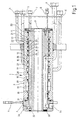
- the rotary feedthrough 1 in this case comprises two rotary parts, a stator 2 and a rotor 3.
- the stator 2 is provided with a flange 4, by means of which the rotary feedthrough is to be fastened at the place of use.
- the rotor 3 is sleeve-shaped and pushed onto the stator 2. Thus, the rotor 3 is rotatable relative to the stator 2 with respect to the axis of rotation D.
- the illustrated embodiment shows how several lines are performed with different sized cross section through a rotary feedthrough.
- the terminal 5 of the rotor 3 is connected to the annular groove 12. Regardless of the angular position of the rotor 3 in relation to the stator 2 thus results in a connection between the Terminal 5 and the axis-parallel bore 32 and thus to the radial bore 34.
- the radial bore 34 can be used for example via an internal thread as a stator-side external connection.
- the connection 9 via the annular groove 15, the axis-parallel bore 33 and the radial bore 35 is performed independently of the angular position of the rotor 3 in relation to the stator 2.
- the external sealing of such a rotary feedthrough can advantageously be improved by providing a leakage oil return in such a way that the high-pressure-carrying channels are shielded towards the outside by the leakage oil return.
- pressures of the order of a few hundred bar are certainly present.
- the high pressure lines are connected via the annular grooves 16, 17, 18 to different high pressure pumps, e.g. a crane hydraulic pump, a rotary pump and an auxiliary pump connected, it is advantageously in the outdoor area thereto, for. provided in the adjacent annular groove 15 a leakage oil return to intercept there penetrating leak oil from the pressure lines.
- the further outward connecting lines can be used for low-pressure channels, for example, for one or more compressed air or fuel lines.
- a hydraulic oil return line 19 is arranged with a large cross-section, which also represents a low-pressure line and at the same time can serve as a leak oil return.
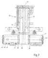
- FIG. 2 now shows a rotary feedthrough 36 according to the invention with a first rotor 37 and a stator 38, the first rotor 37 and the part of the stator 38 located in the region of the first rotor 37 being in accordance with FIG FIG. 1 described structure of a rotary feedthrough corresponds.
- the stator 38 has two extensions 39, 40, which extend transversely to the axis of rotation D 1 on both sides of the stator 38 to the outside. On the extensions 39, 40, a second rotor 41 and a third rotor 42 are pushed.
- the extensions 39, 40 of the stator 38 have according to the structure of the rotary feedthrough according to FIG. 1 Axially parallel bores (not shown in detail) with respect to the axis of rotation D 2 , which are connected to axis-parallel channels (also not shown in detail) with respect to the axis of rotation D 1 .
- the channels arranged in the stator in the area of the first rotor 37 and parallel to the axis of rotation D 1 branch, as it were, into the two extensions 39, 40 into the regions of the second rotor 41 and of the third rotor 42.
- connection openings of the second or third rotor 41, 42 Three such connection openings 43 are shown by way of example on the third rotor 42.
- the connections can be made in a suitable manner, for example via flange connections or screw-in thread.
- a rotary feedthrough according to the invention allows the twisting of the mutual connections about two axes of rotation D 1 , D 2 . If, for example, the connection 46 of the first rotor 37 is connected to the connection opening 44 of the third rotor 42, then Based on the illustrated embodiment immediately recognizable that the connection opening 44 with respect to the terminal 46 both about the rotation axis D 1 and about the rotation axis D 2 is rotatable.
- the rotary feedthrough according to the invention can be used, for example, in an off-highway vehicle with a hydraulic drive whose front part can pivot with respect to the rear part about the axis of rotation D 2 , wherein the front part and the rear part of such a vehicle or its Laufradachsen is simultaneously 29ränkbar about the axis of rotation D 1 . It can thus be created with a rotary feedthrough 36 of the illustrated type an off-road vehicle with hydraulic drive, as it can follow the ground contour even in an extremely cropped terrain without the vehicle rests between the axles or the wheels lose the grip.
- the rotary feedthrough 36 can here as well as the rotary feedthrough 1 not only for performing hydraulic lines, but at the same time of other fluid lines, such as fuel lines, compressed air lines, etc. are used.
- the complete fluid system of a machine or a vehicle can be passed through such multiple rotary joints.
Landscapes
- Engineering & Computer Science (AREA)
- General Engineering & Computer Science (AREA)
- Mechanical Engineering (AREA)
- Joints Allowing Movement (AREA)
- Hydraulic Motors (AREA)
- Quick-Acting Or Multi-Walled Pipe Joints (AREA)
- Motor Power Transmission Devices (AREA)
- Cyclones (AREA)
Claims (11)
- Passage tournant (36) pour le système fluidique d'un système hydraulique comportant un premier élément tournant désigné en tant que premier rotor (37) et un deuxième élément tournant désigné en tant que stator (38), lesquels sont agencés au moins partiellement de manière coaxiale l'un par rapport à l'autre et de manière rotative autour d'un premier axe de rotation D,
caractérisé en ce qu'un troisième élément tournant désigné en tant que deuxième rotor (41) est agencé au moins partiellement de manière coaxiale par rapport à une partie (39) du stator (38) et de manière rotative par rapport à celui-ci autour d'un second axe de rotation D2 différent du premier axe de rotation D1. - Passage tournant selon la revendication 1,
caractérisé en ce que le stator (38) est composé de plusieurs parties. - Passage tournant selon l'une des revendications précédentes, caractérisé en ce qu'il est prévu une liaison à bride tenant à la pression entre les différentes parties de stator.
- Passage tournant selon l'une des revendications précédentes, caractérisé en ce que le premier et/ou les autres rotors (37, 41, 42) sont réalisés au moins partiellement en forme de manchons et entourent une partie correspondante du stator (38).
- Passage tournant selon l'une des revendications précédentes, caractérisé en ce qu'il est prévu un troisième rotor (42).
- Passage tournant selon l'une des revendications précédentes, caractérisé en ce que le troisième rotor (42) est également agencé de manière rotative autour du second axe de rotation D2 du deuxième rotor (41).
- Passage tournant selon l'une des revendications précédentes, caractérisé en ce que le deuxième rotor (41) et le troisième rotor (42) sont agencés des deux côtés du stator (38), de sorte qu'il en résulte un passage tournant (36) en forme de T ou de croix.
- Passage tournant selon l'une des revendications précédentes, caractérisé en ce qu'il est prévu dans le passage tournant un retour de fluide de fuite.
- Passage tournant selon l'une des revendications précédentes, caractérisé en ce que le retour de fluide de fuite est agencé entre une conduite à haute pression et la zone extérieure du passage tournant.
- Machine comportant un système fluidique,
caractérisée en ce qu'il est prévu un passage tournant selon l'une des revendications 1 à 9. - Véhicule comportant un système fluidique,
caractérisé en ce qu'il est prévu un passage tournant selon l'une des revendications 1 à 9.
Applications Claiming Priority (3)
| Application Number | Priority Date | Filing Date | Title |
|---|---|---|---|
| DE10125991A DE10125991A1 (de) | 2001-05-29 | 2001-05-29 | Drehdurchführung für Fuidsysteme |
| DE10125991 | 2001-05-29 | ||
| PCT/DE2002/001705 WO2002097318A1 (fr) | 2001-05-29 | 2002-05-11 | Passage tournant pour systemes fluidiques |
Publications (2)
| Publication Number | Publication Date |
|---|---|
| EP1390657A1 EP1390657A1 (fr) | 2004-02-25 |
| EP1390657B1 true EP1390657B1 (fr) | 2009-03-25 |
Family
ID=7686427
Family Applications (1)
| Application Number | Title | Priority Date | Filing Date |
|---|---|---|---|
| EP02740341A Expired - Lifetime EP1390657B1 (fr) | 2001-05-29 | 2002-05-11 | Passage tournant pour systemes fluidiques |
Country Status (5)
| Country | Link |
|---|---|
| US (1) | US7156426B2 (fr) |
| EP (1) | EP1390657B1 (fr) |
| AT (1) | ATE426773T1 (fr) |
| DE (2) | DE10125991A1 (fr) |
| WO (1) | WO2002097318A1 (fr) |
Families Citing this family (12)
| Publication number | Priority date | Publication date | Assignee | Title |
|---|---|---|---|---|
| US7083200B2 (en) * | 2003-08-28 | 2006-08-01 | Focal Technologies Corporation | Fluid rotary union |
| US20090051164A1 (en) * | 2005-12-16 | 2009-02-26 | Dominik Lirsch | Connection Element for Connecting to a Tubular Piece |
| DE102006048885A1 (de) * | 2006-10-17 | 2008-04-24 | Zf Friedrichshafen Ag | Drehdurchführung, insbesondere für den Antriebsstrang eines Fahrzeugs |
| DE102009012462A1 (de) | 2009-03-12 | 2010-10-07 | Hytrac Gmbh | Drehdurchführung und Dichtelement für eine Drehdurchführung |
| US20140145429A1 (en) * | 2011-07-19 | 2014-05-29 | Volvo Construction Equipment Ab | Swivel joint for construction machinery |
| DE202011051737U1 (de) * | 2011-10-24 | 2011-11-04 | Ptg Reifendruckregelsysteme Gmbh | Drehdurchführung als Teil einer Reifendruckregelanlage eines Fahrzeuges |
| CN103322354A (zh) * | 2013-06-28 | 2013-09-25 | 长治清华机械厂 | 回转接头 |
| WO2015043594A1 (fr) * | 2013-09-25 | 2015-04-02 | Schaeffler Technologies AG & Co. KG | Dispositif de transfert de liquides |
| US9970577B2 (en) | 2013-09-27 | 2018-05-15 | The Procter & Gamble Company | Rotary union |
| DE202015105859U1 (de) | 2015-11-04 | 2017-02-07 | Ptg Reifendruckregelsysteme Gmbh | Radventilanordnung sowie Reifendruckregelanlage mit wenigstens einer solchen Radventilanordnung |
| US11117426B1 (en) | 2021-03-24 | 2021-09-14 | Ptg Reifendruckregelsysteme Gmbh | Rotary transmission leadthrough as part of a tire pressure control system |
| US12135102B2 (en) * | 2023-02-23 | 2024-11-05 | Axis Forestry Inc. | Swivel connector |
Family Cites Families (16)
| Publication number | Priority date | Publication date | Assignee | Title |
|---|---|---|---|---|
| US573280A (en) * | 1896-12-15 | Photo-litho | ||
| US386881A (en) * | 1888-07-31 | William m | ||
| US991501A (en) * | 1908-10-03 | 1911-05-09 | William A Hardwick | Pipe-coupling. |
| US1228541A (en) * | 1916-06-17 | 1917-06-05 | Votaw S Durbin | Swivel-coupling for pipe-lines. |
| US1788500A (en) * | 1926-02-24 | 1931-01-13 | Jr William C Uhri | Swivel joint for plural conduits |
| US2083970A (en) * | 1936-01-06 | 1937-06-15 | Ind Patents Corp | Pipe joint |
| US2139226A (en) * | 1937-05-06 | 1938-12-06 | Ingersoll Rand Co | Water connection |
| DE690434C (de) | 1938-11-03 | 1940-04-25 | Otto Fleischer Dr Ing | Vorrichtung zum Vorpfaenden von Traegern |
| US2354416A (en) * | 1943-05-04 | 1944-07-25 | Chiksan Tool Company | Swing joint |
| US2501638A (en) * | 1948-02-02 | 1950-03-21 | Chiksan Co | Circulating head |
| US2717141A (en) * | 1951-05-17 | 1955-09-06 | Harry F Livingston | Adjustable supports providing universal movement |
| DE1782490U (de) * | 1958-11-29 | 1959-02-05 | Bischoff Werke K G Vorm Pfings | Vielstrom-drehgelenk fuer hydraulische leitungen. |
| US4362324A (en) * | 1980-03-24 | 1982-12-07 | Haskel Engineering & Supply Company | Jointed high pressure conduit |
| DE4318060A1 (de) * | 1993-05-31 | 1994-12-01 | Josef Rupprecht | Schwenkarmvorrichtung |
| US5372389A (en) * | 1993-06-22 | 1994-12-13 | Graco Inc. | Nozzle swivel joint |
| US5405173A (en) * | 1993-08-16 | 1995-04-11 | T & S Brass And Bronze Works, Inc. | Fluid conducting joint |
-
2001
- 2001-05-29 DE DE10125991A patent/DE10125991A1/de not_active Withdrawn
-
2002
- 2002-05-11 EP EP02740341A patent/EP1390657B1/fr not_active Expired - Lifetime
- 2002-05-11 US US10/478,995 patent/US7156426B2/en not_active Expired - Lifetime
- 2002-05-11 AT AT02740341T patent/ATE426773T1/de active
- 2002-05-11 DE DE50213390T patent/DE50213390D1/de not_active Expired - Lifetime
- 2002-05-11 WO PCT/DE2002/001705 patent/WO2002097318A1/fr not_active Ceased
Also Published As
| Publication number | Publication date |
|---|---|
| ATE426773T1 (de) | 2009-04-15 |
| US20040113424A1 (en) | 2004-06-17 |
| WO2002097318A1 (fr) | 2002-12-05 |
| EP1390657A1 (fr) | 2004-02-25 |
| DE10125991A1 (de) | 2002-12-05 |
| US7156426B2 (en) | 2007-01-02 |
| DE50213390D1 (de) | 2009-05-07 |
Similar Documents
| Publication | Publication Date | Title |
|---|---|---|
| EP1390657B1 (fr) | Passage tournant pour systemes fluidiques | |
| EP2586630B1 (fr) | Passage tournant | |
| EP2513547B1 (fr) | Passage de rotation radial avec une douille | |
| DE60205641T2 (de) | Zur verbindung zweier röhrenförmiger elemente verwendete kupplung und montageverfahren dafür | |
| DE69219642T2 (de) | Flüssigkeitssteuerung mit lastgesteuerter Priorität-Durchflussregelmöglichkeit | |
| DE8524633U1 (de) | Luftfeder mit pneumatischen Anschluß | |
| DE19815313C2 (de) | Fahrstabilisator für Kraftfahrzeuge | |
| EP3990790B1 (fr) | Kit de construction avec bloc de commande hydraulique et axe hydraulique | |
| WO2001006116A1 (fr) | Raccord et carter pour un systeme d'injection de carburant pourvu d'un accumulateur de carburant haute pression | |
| DE19815314A1 (de) | Hydraulisch betätigter Drehsteller | |
| DE69812107T2 (de) | Bidirektionale drehkupplung für fluide | |
| DE20121787U1 (de) | Drehdurchführung für Fluidsysteme | |
| DE3630200A1 (de) | Hydraulisches servoventil | |
| DE102019004659A1 (de) | Armatursicherung für hydraulikschlauchkupplungen, baumaschine und verfahren | |
| EP1136337A1 (fr) | Cylindre combiné de frein de service et à ressort | |
| EP2761189B1 (fr) | Vérrin hydraulique avec dispositif de soupape | |
| EP0655558B1 (fr) | Soupape pneumatique avec au moins deux modules fixés l'un à l'autre | |
| DE10243697A1 (de) | Schwenkmotor | |
| DE60008004T2 (de) | Verbindungsanordnung von zwei rohrenden | |
| EP1153216B1 (fr) | Tubulure de raccordement et boitier pour un systeme d'injection de carburant | |
| WO2002037003A1 (fr) | Bloc de commande de sous-groupes soupapes | |
| DE4324666A1 (de) | Drehventil für einen hydraulischen Stempel | |
| DE2359195A1 (de) | Steckverbindung zum verbinden von elektrischen und fluidischen leitungen | |
| EP3165390B1 (fr) | Ensemble moyeu de roue comprenant un moteur hydraulique pivotant | |
| DE4424460C2 (de) | Hydrozyklon |
Legal Events
| Date | Code | Title | Description |
|---|---|---|---|
| PUAI | Public reference made under article 153(3) epc to a published international application that has entered the european phase |
Free format text: ORIGINAL CODE: 0009012 |
|
| 17P | Request for examination filed |
Effective date: 20031030 |
|
| AK | Designated contracting states |
Kind code of ref document: A1 Designated state(s): AT BE CH CY DE DK ES FI FR GB GR IE IT LI LU MC NL PT SE TR |
|
| AX | Request for extension of the european patent |
Extension state: AL LT LV MK RO SI |
|
| GRAP | Despatch of communication of intention to grant a patent |
Free format text: ORIGINAL CODE: EPIDOSNIGR1 |
|
| GRAS | Grant fee paid |
Free format text: ORIGINAL CODE: EPIDOSNIGR3 |
|
| GRAA | (expected) grant |
Free format text: ORIGINAL CODE: 0009210 |
|
| AK | Designated contracting states |
Kind code of ref document: B1 Designated state(s): AT BE CH CY DE DK ES FI FR GB GR IE IT LI LU MC NL PT SE TR |
|
| REG | Reference to a national code |
Ref country code: GB Ref legal event code: FG4D Free format text: NOT ENGLISH |
|
| REG | Reference to a national code |
Ref country code: CH Ref legal event code: EP |
|
| REG | Reference to a national code |
Ref country code: IE Ref legal event code: FG4D Free format text: LANGUAGE OF EP DOCUMENT: GERMAN |
|
| REF | Corresponds to: |
Ref document number: 50213390 Country of ref document: DE Date of ref document: 20090507 Kind code of ref document: P |
|
| REG | Reference to a national code |
Ref country code: CH Ref legal event code: NV Representative=s name: KELLER & PARTNER PATENTANWAELTE AG |
|
| PG25 | Lapsed in a contracting state [announced via postgrant information from national office to epo] |
Ref country code: FI Free format text: LAPSE BECAUSE OF FAILURE TO SUBMIT A TRANSLATION OF THE DESCRIPTION OR TO PAY THE FEE WITHIN THE PRESCRIBED TIME-LIMIT Effective date: 20090325 |
|
| PG25 | Lapsed in a contracting state [announced via postgrant information from national office to epo] |
Ref country code: SE Free format text: LAPSE BECAUSE OF FAILURE TO SUBMIT A TRANSLATION OF THE DESCRIPTION OR TO PAY THE FEE WITHIN THE PRESCRIBED TIME-LIMIT Effective date: 20090625 |
|
| NLV1 | Nl: lapsed or annulled due to failure to fulfill the requirements of art. 29p and 29m of the patents act | ||
| REG | Reference to a national code |
Ref country code: IE Ref legal event code: FD4D |
|
| PG25 | Lapsed in a contracting state [announced via postgrant information from national office to epo] |
Ref country code: PT Free format text: LAPSE BECAUSE OF FAILURE TO SUBMIT A TRANSLATION OF THE DESCRIPTION OR TO PAY THE FEE WITHIN THE PRESCRIBED TIME-LIMIT Effective date: 20090901 Ref country code: ES Free format text: LAPSE BECAUSE OF FAILURE TO SUBMIT A TRANSLATION OF THE DESCRIPTION OR TO PAY THE FEE WITHIN THE PRESCRIBED TIME-LIMIT Effective date: 20090706 |
|
| PG25 | Lapsed in a contracting state [announced via postgrant information from national office to epo] |
Ref country code: NL Free format text: LAPSE BECAUSE OF FAILURE TO SUBMIT A TRANSLATION OF THE DESCRIPTION OR TO PAY THE FEE WITHIN THE PRESCRIBED TIME-LIMIT Effective date: 20090325 |
|
| PG25 | Lapsed in a contracting state [announced via postgrant information from national office to epo] |
Ref country code: MC Free format text: LAPSE BECAUSE OF NON-PAYMENT OF DUE FEES Effective date: 20090531 |
|
| PG25 | Lapsed in a contracting state [announced via postgrant information from national office to epo] |
Ref country code: IE Free format text: LAPSE BECAUSE OF FAILURE TO SUBMIT A TRANSLATION OF THE DESCRIPTION OR TO PAY THE FEE WITHIN THE PRESCRIBED TIME-LIMIT Effective date: 20090325 Ref country code: DK Free format text: LAPSE BECAUSE OF FAILURE TO SUBMIT A TRANSLATION OF THE DESCRIPTION OR TO PAY THE FEE WITHIN THE PRESCRIBED TIME-LIMIT Effective date: 20090325 |
|
| PLBE | No opposition filed within time limit |
Free format text: ORIGINAL CODE: 0009261 |
|
| STAA | Information on the status of an ep patent application or granted ep patent |
Free format text: STATUS: NO OPPOSITION FILED WITHIN TIME LIMIT |
|
| 26N | No opposition filed |
Effective date: 20091229 |
|
| PG25 | Lapsed in a contracting state [announced via postgrant information from national office to epo] |
Ref country code: GR Free format text: LAPSE BECAUSE OF FAILURE TO SUBMIT A TRANSLATION OF THE DESCRIPTION OR TO PAY THE FEE WITHIN THE PRESCRIBED TIME-LIMIT Effective date: 20090626 |
|
| PG25 | Lapsed in a contracting state [announced via postgrant information from national office to epo] |
Ref country code: LU Free format text: LAPSE BECAUSE OF NON-PAYMENT OF DUE FEES Effective date: 20090511 |
|
| PG25 | Lapsed in a contracting state [announced via postgrant information from national office to epo] |
Ref country code: TR Free format text: LAPSE BECAUSE OF FAILURE TO SUBMIT A TRANSLATION OF THE DESCRIPTION OR TO PAY THE FEE WITHIN THE PRESCRIBED TIME-LIMIT Effective date: 20090325 |
|
| PG25 | Lapsed in a contracting state [announced via postgrant information from national office to epo] |
Ref country code: CY Free format text: LAPSE BECAUSE OF FAILURE TO SUBMIT A TRANSLATION OF THE DESCRIPTION OR TO PAY THE FEE WITHIN THE PRESCRIBED TIME-LIMIT Effective date: 20090325 |
|
| PGFP | Annual fee paid to national office [announced via postgrant information from national office to epo] |
Ref country code: GB Payment date: 20140521 Year of fee payment: 13 |
|
| PGFP | Annual fee paid to national office [announced via postgrant information from national office to epo] |
Ref country code: CH Payment date: 20140521 Year of fee payment: 13 Ref country code: AT Payment date: 20140512 Year of fee payment: 13 Ref country code: FR Payment date: 20140527 Year of fee payment: 13 |
|
| PGFP | Annual fee paid to national office [announced via postgrant information from national office to epo] |
Ref country code: BE Payment date: 20140523 Year of fee payment: 13 |
|
| REG | Reference to a national code |
Ref country code: CH Ref legal event code: PCAR Free format text: NEW ADDRESS: EIGERSTRASSE 2 POSTFACH, 3000 BERN 14 (CH) |
|
| PGFP | Annual fee paid to national office [announced via postgrant information from national office to epo] |
Ref country code: DE Payment date: 20150615 Year of fee payment: 14 |
|
| PGFP | Annual fee paid to national office [announced via postgrant information from national office to epo] |
Ref country code: IT Payment date: 20150514 Year of fee payment: 14 |
|
| REG | Reference to a national code |
Ref country code: CH Ref legal event code: PL |
|
| REG | Reference to a national code |
Ref country code: AT Ref legal event code: MM01 Ref document number: 426773 Country of ref document: AT Kind code of ref document: T Effective date: 20150511 |
|
| GBPC | Gb: european patent ceased through non-payment of renewal fee |
Effective date: 20150511 |
|
| PG25 | Lapsed in a contracting state [announced via postgrant information from national office to epo] |
Ref country code: CH Free format text: LAPSE BECAUSE OF NON-PAYMENT OF DUE FEES Effective date: 20150531 Ref country code: LI Free format text: LAPSE BECAUSE OF NON-PAYMENT OF DUE FEES Effective date: 20150531 |
|
| REG | Reference to a national code |
Ref country code: FR Ref legal event code: ST Effective date: 20160129 |
|
| PG25 | Lapsed in a contracting state [announced via postgrant information from national office to epo] |
Ref country code: AT Free format text: LAPSE BECAUSE OF NON-PAYMENT OF DUE FEES Effective date: 20150511 |
|
| PG25 | Lapsed in a contracting state [announced via postgrant information from national office to epo] |
Ref country code: GB Free format text: LAPSE BECAUSE OF NON-PAYMENT OF DUE FEES Effective date: 20150511 |
|
| PG25 | Lapsed in a contracting state [announced via postgrant information from national office to epo] |
Ref country code: FR Free format text: LAPSE BECAUSE OF NON-PAYMENT OF DUE FEES Effective date: 20150601 |
|
| REG | Reference to a national code |
Ref country code: DE Ref legal event code: R119 Ref document number: 50213390 Country of ref document: DE |
|
| PG25 | Lapsed in a contracting state [announced via postgrant information from national office to epo] |
Ref country code: IT Free format text: LAPSE BECAUSE OF NON-PAYMENT OF DUE FEES Effective date: 20160511 |
|
| PG25 | Lapsed in a contracting state [announced via postgrant information from national office to epo] |
Ref country code: DE Free format text: LAPSE BECAUSE OF NON-PAYMENT OF DUE FEES Effective date: 20161201 |
|
| PG25 | Lapsed in a contracting state [announced via postgrant information from national office to epo] |
Ref country code: BE Free format text: LAPSE BECAUSE OF NON-PAYMENT OF DUE FEES Effective date: 20150531 |