EP1390657B1 - Rotary transmission leadthrough for fluid systems - Google Patents
Rotary transmission leadthrough for fluid systems Download PDFInfo
- Publication number
- EP1390657B1 EP1390657B1 EP02740341A EP02740341A EP1390657B1 EP 1390657 B1 EP1390657 B1 EP 1390657B1 EP 02740341 A EP02740341 A EP 02740341A EP 02740341 A EP02740341 A EP 02740341A EP 1390657 B1 EP1390657 B1 EP 1390657B1
- Authority
- EP
- European Patent Office
- Prior art keywords
- rotor
- stator
- rotary
- rotary transmission
- transmission leadthrough
- Prior art date
- Legal status (The legal status is an assumption and is not a legal conclusion. Google has not performed a legal analysis and makes no representation as to the accuracy of the status listed.)
- Expired - Lifetime
Links
- 239000012530 fluid Substances 0.000 title claims abstract description 30
- 230000005540 biological transmission Effects 0.000 title claims abstract 16
- 239000003921 oil Substances 0.000 description 11
- 239000000446 fuel Substances 0.000 description 3
- 238000007789 sealing Methods 0.000 description 3
- 238000010276 construction Methods 0.000 description 2
- 230000005484 gravity Effects 0.000 description 2
- 239000010720 hydraulic oil Substances 0.000 description 2
- 230000006978 adaptation Effects 0.000 description 1
- 230000009286 beneficial effect Effects 0.000 description 1
- 238000011109 contamination Methods 0.000 description 1
- 230000001419 dependent effect Effects 0.000 description 1
- 238000011161 development Methods 0.000 description 1
- 230000018109 developmental process Effects 0.000 description 1
- 230000007613 environmental effect Effects 0.000 description 1
- 230000002349 favourable effect Effects 0.000 description 1
- 238000009434 installation Methods 0.000 description 1
- 238000012423 maintenance Methods 0.000 description 1
- 238000004519 manufacturing process Methods 0.000 description 1
- 230000000149 penetrating effect Effects 0.000 description 1
- 230000000284 resting effect Effects 0.000 description 1
Images
Classifications
-
- F—MECHANICAL ENGINEERING; LIGHTING; HEATING; WEAPONS; BLASTING
- F16—ENGINEERING ELEMENTS AND UNITS; GENERAL MEASURES FOR PRODUCING AND MAINTAINING EFFECTIVE FUNCTIONING OF MACHINES OR INSTALLATIONS; THERMAL INSULATION IN GENERAL
- F16L—PIPES; JOINTS OR FITTINGS FOR PIPES; SUPPORTS FOR PIPES, CABLES OR PROTECTIVE TUBING; MEANS FOR THERMAL INSULATION IN GENERAL
- F16L39/00—Joints or fittings for double-walled or multi-channel pipes or pipe assemblies
- F16L39/04—Joints or fittings for double-walled or multi-channel pipes or pipe assemblies allowing adjustment or movement
Definitions
- the invention relates to a rotary feedthrough for fluid systems according to the preamble of claim 1.
- a rotary feedthrough is for example from DE-U 1782490 known.
- fluid systems in particular in machines or vehicles with hydraulic drive rotary feedthroughs are used to ensure fluid channels between mutually movable components.
- Such fluid systems are used, for example, in construction machines or agricultural machines.
- Known rotary unions are used, inter alia, to allow cross-country vehicles with hydraulic drive entanglement between the front and rear axles, since the mutual connections of such a rotary feedthrough allow the mutual rotation about a rotation axis.
- Known rotary unions usually consist of two at least partially nested rotating elements, one of which is referred to as a stator and the other as a rotor.
- the rotary element designated as a stator is stationary relative to the reference system, for example a machine frame, while the rotary element designated rotor is rotatable with respect to this reference system.
- stator and rotor is used only to distinguish two rotary elements, wherein, depending on the reference system, the rotary element called a stator does not have to be statically fixed.
- the fluid lines are guided over outer or inner grooves of the stator and / or the rotor and thus have the shape of an annular groove or a Ringsegmentnut.
- many different fluid lines e.g. for hydraulic oil, compressed air, fuel, etc. are performed.
- the object of the invention is to propose a rotary feedthrough, by means of which increases the mobility of a fluid system, in particular a hydraulic system and thus new applications are developed.
- At least one further rotor is provided, which is at least partially coaxial to a part of the stator and to this about a second, different from the first axis of rotation of the first rotor axis of rotation.
- a rotary feedthrough according to the invention can also be used to allow in addition to the crossing of the wheels and steering movements of two axes to each other, as is the case with so-called articulated steering.
- Such vehicles buckle when steering around a vertical axis of rotation and are considerably more agile than vehicles with conventional Radlenkisme.
- a rotary feedthrough according to the invention can be mounted as a central unit for a plurality of fluid lines and is able to ensure the required mobility of the fluid lines permanently sealed even at high working pressures.
- the stator is constructed in several parts.
- the production and installation of a rotary feedthrough according to the invention is considerably facilitated.
- such a rotary feedthrough also maintenance and repair friendly, since they partially at the site can be dismantled and repaired by replacing individual stator spare parts is possible.
- the first and the second rotor are at least partially sleeve-shaped, so that they can enclose the corresponding counterpart of the stator.
- This corresponds to the design of known rotary unions and in particular offers the advantage of attaching different fluid ports outside the rotor in different axial position.
- the reverse construction is conceivable, i. a sleeve-shaped configuration of the stator, in which case one or both rotors must be introduced as an inner part in such a stator.
- a third rotor is provided.
- Such a third rotor can be arranged to be rotatable about a third axis of rotation.
- the third rotor can be rotatably connected either to the above-mentioned stator or to one of the two aforementioned rotors.
- That one rotor must be provided with a part which is designed as a stator for the third rotor, which includes the lines to be carried out.
- the rotary feedthrough according to the invention still represents a unit to be handled as a whole with the resulting advantages in terms of assembly, repair and the number of parts required.
- the third rotor can also be designed so that it is rotatable about the same axis of rotation, as one of the two aforementioned rotors.
- the third rotor allows greater freedom in the spatial configuration of a rotary feedthrough according to the invention.
- a rotary feedthrough for fluid systems usually many fluid lines are rotatably coupled together.
- the corresponding channels in the rotor or in the stator are in this case arranged axially annularly or annular segment-shaped. If the length of a rotor and the associated stator is limited for design reasons, the reliable implementation of further fluid channels can be ensured by attaching a further rotor.
- weight distribution can be achieved with the help of another third rotor.
- a second and a third rotor which are arranged on both sides of a stator, are combined with the first rotor in a cross-shaped or T-shaped manner, a center of gravity position results in the vicinity of the central axis of the rotary feedthrough in the longitudinal direction of the first rotor.
- Such weight distribution is, for example, when used in Vehicles beneficial to ensure a balanced ride in curves or on slopes.
- a leakage fluid return e.g. for leakage oil, integrated in the rotary feedthrough.
- This is generally advantageous in all types of hydraulic systems, since the external seal of the rotary feedthrough is significantly improved by this measure.
- one or more leakage fluid recirculations are provided in the area of the rotary feedthrough between a pressure line and the outer area. Due to the non-pressurized leakage fluid return, pressurized lines are shielded to a certain extent further inside the rotary union. The external tightness of the rotary feedthrough is in this arrangement ultimately only between the non-pressurized leakage fluid line and the external environment to produce. However, the sealing of a non-pressurized line can be realized considerably easier and better than is the case with high-pressure lines.
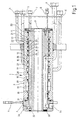
- the rotary feedthrough 1 in this case comprises two rotary parts, a stator 2 and a rotor 3.
- the stator 2 is provided with a flange 4, by means of which the rotary feedthrough is to be fastened at the place of use.
- the rotor 3 is sleeve-shaped and pushed onto the stator 2. Thus, the rotor 3 is rotatable relative to the stator 2 with respect to the axis of rotation D.
- the illustrated embodiment shows how several lines are performed with different sized cross section through a rotary feedthrough.
- the terminal 5 of the rotor 3 is connected to the annular groove 12. Regardless of the angular position of the rotor 3 in relation to the stator 2 thus results in a connection between the Terminal 5 and the axis-parallel bore 32 and thus to the radial bore 34.
- the radial bore 34 can be used for example via an internal thread as a stator-side external connection.
- the connection 9 via the annular groove 15, the axis-parallel bore 33 and the radial bore 35 is performed independently of the angular position of the rotor 3 in relation to the stator 2.
- the external sealing of such a rotary feedthrough can advantageously be improved by providing a leakage oil return in such a way that the high-pressure-carrying channels are shielded towards the outside by the leakage oil return.
- pressures of the order of a few hundred bar are certainly present.
- the high pressure lines are connected via the annular grooves 16, 17, 18 to different high pressure pumps, e.g. a crane hydraulic pump, a rotary pump and an auxiliary pump connected, it is advantageously in the outdoor area thereto, for. provided in the adjacent annular groove 15 a leakage oil return to intercept there penetrating leak oil from the pressure lines.
- the further outward connecting lines can be used for low-pressure channels, for example, for one or more compressed air or fuel lines.
- a hydraulic oil return line 19 is arranged with a large cross-section, which also represents a low-pressure line and at the same time can serve as a leak oil return.
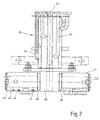
- FIG. 2 now shows a rotary feedthrough 36 according to the invention with a first rotor 37 and a stator 38, the first rotor 37 and the part of the stator 38 located in the region of the first rotor 37 being in accordance with FIG FIG. 1 described structure of a rotary feedthrough corresponds.
- the stator 38 has two extensions 39, 40, which extend transversely to the axis of rotation D 1 on both sides of the stator 38 to the outside. On the extensions 39, 40, a second rotor 41 and a third rotor 42 are pushed.
- the extensions 39, 40 of the stator 38 have according to the structure of the rotary feedthrough according to FIG. 1 Axially parallel bores (not shown in detail) with respect to the axis of rotation D 2 , which are connected to axis-parallel channels (also not shown in detail) with respect to the axis of rotation D 1 .
- the channels arranged in the stator in the area of the first rotor 37 and parallel to the axis of rotation D 1 branch, as it were, into the two extensions 39, 40 into the regions of the second rotor 41 and of the third rotor 42.
- connection openings of the second or third rotor 41, 42 Three such connection openings 43 are shown by way of example on the third rotor 42.
- the connections can be made in a suitable manner, for example via flange connections or screw-in thread.
- a rotary feedthrough according to the invention allows the twisting of the mutual connections about two axes of rotation D 1 , D 2 . If, for example, the connection 46 of the first rotor 37 is connected to the connection opening 44 of the third rotor 42, then Based on the illustrated embodiment immediately recognizable that the connection opening 44 with respect to the terminal 46 both about the rotation axis D 1 and about the rotation axis D 2 is rotatable.
- the rotary feedthrough according to the invention can be used, for example, in an off-highway vehicle with a hydraulic drive whose front part can pivot with respect to the rear part about the axis of rotation D 2 , wherein the front part and the rear part of such a vehicle or its Laufradachsen is simultaneously 29ränkbar about the axis of rotation D 1 . It can thus be created with a rotary feedthrough 36 of the illustrated type an off-road vehicle with hydraulic drive, as it can follow the ground contour even in an extremely cropped terrain without the vehicle rests between the axles or the wheels lose the grip.
- the rotary feedthrough 36 can here as well as the rotary feedthrough 1 not only for performing hydraulic lines, but at the same time of other fluid lines, such as fuel lines, compressed air lines, etc. are used.
- the complete fluid system of a machine or a vehicle can be passed through such multiple rotary joints.
Landscapes
- Engineering & Computer Science (AREA)
- General Engineering & Computer Science (AREA)
- Mechanical Engineering (AREA)
- Joints Allowing Movement (AREA)
- Hydraulic Motors (AREA)
- Quick-Acting Or Multi-Walled Pipe Joints (AREA)
- Motor Power Transmission Devices (AREA)
- Cyclones (AREA)
Abstract
Description
Die Erfindung betrifft eine Drehdurchführung für Fluidsysteme nach dem Oberbegriff des Anspruchs 1. Solch eine Drehdurchführung ist beispielsweise aus der
In Fluidsystemen, insbesondere in Maschinen oder Fahrzeugen mit Hydraulikantrieb werden Drehdurchführungen verwendet, um Fluidkanäle zwischen zueinander beweglichen Bauteilen sicherzustellen. Solche Fluidsysteme finden beispielsweise bei Baumaschinen oder Landmaschinen Anwendung.In fluid systems, in particular in machines or vehicles with hydraulic drive rotary feedthroughs are used to ensure fluid channels between mutually movable components. Such fluid systems are used, for example, in construction machines or agricultural machines.
Bekannte Drehdurchführungen werden unter anderem eingesetzt, um bei geländegängigen Fahrzeugen mit Hydraulikantrieb eine Verschränkung zwischen der Vorder- und der Hinterachse zu ermöglichen, da die beiderseitigen Anschlüsse einer solchen Drehdurchführung die gegenseitige Verdrehung um eine Drehachse erlauben.Known rotary unions are used, inter alia, to allow cross-country vehicles with hydraulic drive entanglement between the front and rear axles, since the mutual connections of such a rotary feedthrough allow the mutual rotation about a rotation axis.
Bisherige Geländefahrzeuge können dem Verlauf eines kupierten Geländes nur bedingt folgen, da bei einer zu starken Änderung des Neigungswinkels das Fahrzeug entweder am Boden aufsitzt oder aber bei ausreichender Geschwindigkeit die Laufräder einer Achse vom Boden abheben. Bekannte Drehdurchführungen bestehen in der Regel aus zwei wenigstens teilweise ineinander gesteckten Drehelementen, wovon eines als Stator und das andere als Rotor bezeichnet wird. Das als Stator bezeichnete Drehelement ist hierbei bezogen auf das Bezugssystem, beispielsweise einen Maschinenrahmen ortsfest, während das als Rotor bezeichnete Drehelement bezüglich diesem Bezugssystem verdrehbar ist. Im Folgenden wird die Bezeichnung Stator und Rotor lediglich zur Unterscheidung zweier Drehelemente verwendet, wobei je nach Bezugssystem das als Stator bezeichnete Drehelement nicht statisch fixiert sein muss.Previous all-terrain vehicles can follow the course of a cropped terrain only conditionally, since too strong a change in the angle of inclination, the vehicle is either seated on the ground or at sufficient speed to lift the wheels of an axle from the ground. Known rotary unions usually consist of two at least partially nested rotating elements, one of which is referred to as a stator and the other as a rotor. In this case, the rotary element designated as a stator is stationary relative to the reference system, for example a machine frame, while the rotary element designated rotor is rotatable with respect to this reference system. In the following, the term stator and rotor is used only to distinguish two rotary elements, wherein, depending on the reference system, the rotary element called a stator does not have to be statically fixed.
Die Fluidleitungen werden hierbei über Außen- bzw. Innennuten des Stators und/oder des Rotors geführt und weisen demnach die Form einer Ringnut oder einer Ringsegmentnut auf. Durch eine solche Drehdurchführung können viele verschiedene Fluidleitungen, z.B. für Hydrauliköl, Pressluft, Treibstoff, usw. geführt werden.The fluid lines are guided over outer or inner grooves of the stator and / or the rotor and thus have the shape of an annular groove or a Ringsegmentnut. By such a rotary feedthrough, many different fluid lines, e.g. for hydraulic oil, compressed air, fuel, etc. are performed.
Aufgabe der Erfindung ist es, eine Drehdurchführung vorzuschlagen, mittels der die Beweglichkeit eines Fluidsystems, insbesondere eines Hydrauliksystems erhöht und somit neue Anwendungsgebiete erschlossen werden.The object of the invention is to propose a rotary feedthrough, by means of which increases the mobility of a fluid system, in particular a hydraulic system and thus new applications are developed.
Diese Aufgabe wird ausgehend von einer Drehdurchführung der einleitend genannten Art durch die kennzeichnenden Merkmale des Anspruchs 1 gelöst.This object is achieved on the basis of a rotary feedthrough of the aforementioned type by the characterizing features of claim 1.
Durch die in den Unteransprüchen genannten Maßnahmen sind vorteilhafte Ausführungen und Weiterbildungen der Erfindung möglich.The measures mentioned in the dependent claims advantageous embodiments and developments of the invention are possible.
Dementsprechend wird bei einer erfindungsgemäßen Drehdurchführung wenigstens ein weiterer Rotor vorgesehen, der wenigstens teilweise zu einem Teil des Stators koaxial und zu diesem um eine zweite, von der ersten Drehachse des ersten Rotors verschiedene Drehachse drehbar ist.Accordingly, in a rotary feedthrough according to the invention at least one further rotor is provided, which is at least partially coaxial to a part of the stator and to this about a second, different from the first axis of rotation of the first rotor axis of rotation.
Hierdurch ergibt sich eine Drehdurchführung, die für das zugehörige Fluidsystem neue Anwendungsmöglichkeiten erschließt. So kann beispielsweise im Falle eines Hydrauliksystems für geländegängige Fahrzeuge nicht nur die Verschränkung der Achsen, sondern eine Schwenkbewegung zwischen dem Vorder- und der Hinterteil des Fahrzeugs vorgesehen werden. So kann beispielsweise in einem solchen Fahrzeug ein Knickgelenk vorgesehen werden, das ein Knicken des Fahrzeugs um eine horizontale Drehachse erlaubt. Ein solches Fahrzeug ist in der Lage, auch in extrem kupiertem Gelände der Bodenkontur zu folgen, ohne dass das Fahrzeug auf dem Boden aufliegt oder die Laufräder vom Boden abheben.This results in a rotary feedthrough, which opens up new applications for the associated fluid system. Thus, for example, in the case of a hydraulic system for all-terrain vehicles not only the interlocking of the axles, but a pivoting movement between the front and the rear of the vehicle can be provided. Thus, for example, in such a vehicle, an articulated joint can be provided, which allows buckling of the vehicle about a horizontal axis of rotation. Such a vehicle is able to follow the ground contour even in extremely hilly terrain without the vehicle resting on the ground or lifting the wheels off the ground.
In einer anderen Ausführungsform kann eine erfindungsgemäße Drehdurchführung auch dadurch verwendet werden, neben dem Verschränken der Laufräder auch Lenkbewegungen zweier Achsen zueinander zu ermöglichen, wie dies bei sogenannten Knicklenkungen der Fall ist. Derartige Fahrzeuge knicken beim Lenken um eine vertikale Drehachse ein und sind erheblich wendiger als Fahrzeuge mit herkömmlichen Radlenkungen.In another embodiment, a rotary feedthrough according to the invention can also be used to allow in addition to the crossing of the wheels and steering movements of two axes to each other, as is the case with so-called articulated steering. Such vehicles buckle when steering around a vertical axis of rotation and are considerably more agile than vehicles with conventional Radlenkungen.
Eine erfindungsgemäße Drehdurchführung kann als zentrale Baueinheit für eine Vielzahl von Fluidleitungen angebracht werden und ist in der Lage, die erforderliche Beweglichkeit der Fluidleitungen dauerhaft dichtend auch bei hohen Arbeitsdrücken zu gewährleisten.A rotary feedthrough according to the invention can be mounted as a central unit for a plurality of fluid lines and is able to ensure the required mobility of the fluid lines permanently sealed even at high working pressures.
In einer Weiterbildung der Erfindung wird der Stator mehrteilig aufgebaut. Hierdurch wird die Fertigung und Montage einer erfindungsgemäßen Drehdurchführung erheblich erleichtert. Insbesondere ergibt sich eine größere Gestaltungsfreiheit für konstruktive Detaillösungen bei einer erfindungsgemäßen Drehdurchführung. Darüber hinaus ist eine derartige Drehdurchführung auch wartungs- und reparaturfreundlicher, da sie teilweise am Einsatzort zerlegbar ist und eine Reparatur durch Austausch einzelner Stator-Ersatzteile möglich ist.In one embodiment of the invention, the stator is constructed in several parts. As a result, the production and installation of a rotary feedthrough according to the invention is considerably facilitated. In particular, there is a greater freedom of design for detailed structural solutions in a rotary feedthrough according to the invention. In addition, such a rotary feedthrough also maintenance and repair friendly, since they partially at the site can be dismantled and repaired by replacing individual stator spare parts is possible.
Da derartige mehrteilige Statoren auch hohen Arbeitsdrücken im montierten Zustand standhalten müssen, ist eine dichte Verbindung zwischen den einzelnen Teilen zwingend erforderlich. Hierbei haben sich Flanschverbindungen mit entsprechenden Dichtflächen und Einlegedichtungen bewährt. Darüber hinaus können an einem derartigen Flansch zugleich Halteelemente zur Befestigung der erfindungsgemäßen Drehdurchführung am Einsatzort angebracht werden.Since such multi-part stators must withstand high working pressures in the mounted state, a tight connection between the individual parts is absolutely necessary. This flange connections have proven with corresponding sealing surfaces and insert seals. In addition, retaining elements for fastening the rotary union according to the invention at the place of use can be attached to such a flange at the same time.
In einer besonderen Ausführungsform der Erfindung werden der erste und der zweite Rotor wenigstens teilweise hülsenförmig ausgebildet, so dass sie das entsprechende Gegenstück des Stators umschließen können. Dies entspricht der Bauform bekannter Drehdurchführungen und bietet insbesondere den Vorteil, verschiedene Fluidanschlüsse außen am Rotor in unterschiedlicher axialer Position anzubringen. Grundsätzlich ist jedoch auch die umgekehrte Bauform denkbar, d.h. eine hülsenförmige Ausgestaltung des Stators, wobei in diesem Fall ein oder beide Rotoren als Innenteil in einen solchen Stator eingebracht werden müssen.In a particular embodiment of the invention, the first and the second rotor are at least partially sleeve-shaped, so that they can enclose the corresponding counterpart of the stator. This corresponds to the design of known rotary unions and in particular offers the advantage of attaching different fluid ports outside the rotor in different axial position. In principle, however, the reverse construction is conceivable, i. a sleeve-shaped configuration of the stator, in which case one or both rotors must be introduced as an inner part in such a stator.
In einer weiteren vorteilhaften Ausführungsform der Erfindung wird ein dritter Rotor vorgesehen. Ein solcher dritter Rotor kann dabei um eine dritte Drehachse drehbar angeordnet werden. Dabei kann der dritte Rotor je nach Anwendungsfall entweder mit dem oben genannten Stator drehbar verbunden werden oder aber mit einem der beiden vorgenannten Rotoren. Zur Verbindung des dritten Rotors mit einem der beiden vorgenannten Rotoren, muss derjenige Rotor mit einem Teil versehen werden, das als Stator für den dritten Rotor ausgebildet ist, der die durchzuführenden Leitungen beinhaltet. Eine solche Bauform bringt einen zusätzlichen Freiheitsgrad in der Verdrehbarkeit der Drehdurchführung mit sich, so dass beispielsweise ein geländegängiges Fahrzeug mit einer so ausgebildeten Drehdurchführung eine Verschränkung der Achsen, eine Knicklenkung und zugleich eine Bodenanpassung durch ein Knickgelenk um eine horizontale Achse ermöglicht.In a further advantageous embodiment of the invention, a third rotor is provided. Such a third rotor can be arranged to be rotatable about a third axis of rotation. Depending on the application, the third rotor can be rotatably connected either to the above-mentioned stator or to one of the two aforementioned rotors. To connect the third rotor with one of the two aforementioned rotors, that one rotor must be provided with a part which is designed as a stator for the third rotor, which includes the lines to be carried out. Such a design brings with it an additional degree of freedom in the rotatability of the rotary feedthrough itself, so that, for example, an all-terrain vehicle with a rotary feedthrough formed in this way enables an interlocking of the axles, an articulated steering and, at the same time, a ground adaptation by means of an articulated joint about a horizontal axis.
Dabei stellt die erfindungsgemäße Drehdurchführung nach wie vor eine als Ganzes handzuhabende Baueinheit mit den sich dadurch ergebenden Vorteilen hinsichtlich der Montage, der Reparatur sowie der Anzahl der erforderlichen Teile dar.In this case, the rotary feedthrough according to the invention still represents a unit to be handled as a whole with the resulting advantages in terms of assembly, repair and the number of parts required.
Der dritte Rotor kann jedoch auch so ausgebildet sein, dass er um die gleiche Drehachse drehbar angeordnet ist, wie einer der beiden vorgenannten Rotoren. In diesem Fall ermöglicht der dritte Rotor eine größere Freiheit in der räumlichen Ausgestaltung einer erfindungsgemäßen Drehdurchführung. Bei einer Drehdurchführung für Fluidsysteme werden, wie oben angeführt, in der Regel sehr viele Fluidleitungen drehbar miteinander gekoppelt. Die entsprechenden Kanäle im Rotor bzw. im Stator sind hierbei axial voneinander ringförmig oder ringsegmentförmig angeordnet. Sofern die Länge eines Rotors sowie des dazugehörigen Statorteils aus konstruktiven Gründen beschränkt ist, kann durch das Anbringen eines weiteren Rotors die zuverlässige Durchführung weiterer Fluidkanäle gewährleistet werden.However, the third rotor can also be designed so that it is rotatable about the same axis of rotation, as one of the two aforementioned rotors. In this case, the third rotor allows greater freedom in the spatial configuration of a rotary feedthrough according to the invention. In a rotary feedthrough for fluid systems, as stated above, usually many fluid lines are rotatably coupled together. The corresponding channels in the rotor or in the stator are in this case arranged axially annularly or annular segment-shaped. If the length of a rotor and the associated stator is limited for design reasons, the reliable implementation of further fluid channels can be ensured by attaching a further rotor.
Darüber hinaus kann unter Beibehaltung einer hohen Anzahl von Fluidkanälen eine je nach Anwendungsfall günstiger Gewichtsverteilung mit Hilfe eines weiteren dritten Rotors erzielt werden. Wird beispielsweise in einer vorteilhaften Ausführungsform ein zweiter und ein dritter Rotor, die beidseits eines Stators angeordnet sind, mit dem ersten Rotor kreuz bzw. T-förmig kombiniert, so ergibt sich eine Schwerpunktslage in der Nähe der Mittelachse der Drehdurchführung in Längsrichtung des ersten Rotors. Eine solche Gewichtsverteilung ist beispielsweise beim Einsatz in Fahrzeugen von Vorteil, um ein ausgewogenes Fahrverhalten in Kurven oder in Hanglage zu gewährleisten.In addition, while maintaining a high number of fluid channels depending on the application favorable weight distribution can be achieved with the help of another third rotor. For example, in an advantageous embodiment, if a second and a third rotor, which are arranged on both sides of a stator, are combined with the first rotor in a cross-shaped or T-shaped manner, a center of gravity position results in the vicinity of the central axis of the rotary feedthrough in the longitudinal direction of the first rotor. Such weight distribution is, for example, when used in Vehicles beneficial to ensure a balanced ride in curves or on slopes.
In einer besonderen Ausführungsform einer Fluiddurchführung gemäß der Erfindung wird zudem eine Leckfluidrückführung, z.B. für Lecköl, in die Drehdurchführung integriert. Dies ist generell bei allen Arten von Hydrauliksystemen von Vorteil, da die Außendichtigkeit der Drehdurchführung durch diese Maßnahme deutlich verbessert wird.In a particular embodiment of a fluid passage according to the invention, a leakage fluid return, e.g. for leakage oil, integrated in the rotary feedthrough. This is generally advantageous in all types of hydraulic systems, since the external seal of the rotary feedthrough is significantly improved by this measure.
Insbesondere bei einem Einsatz in einem Fahrzeug ist die Außendichtigkeit von besonders großer Bedeutung, da hierdurch nicht nur das äußere Erscheinungsbild der Drehdurchführung betroffen ist, sondern auch die Ölverluste deutlich reduziert, wenn nicht ganz vermieden werden. Ölverluste sind bei Fahrzeugen vor allem aus Gründen der Umweltkontamination unerwünscht. Darüber hinaus müssen übermäßige Ölverluste im Ölvorrat regelmäßig ergänzt werden.In particular, when used in a vehicle, the external density of particularly great importance, since this not only the appearance of the rotary feedthrough is affected, but also significantly reduces the oil losses, if not completely avoided. Oil losses are undesirable in vehicles, especially for reasons of environmental contamination. In addition, excessive oil losses in the oil supply must be added regularly.
Vorteilhafterweise werden eine oder mehrere Leckfluidrückführungen im Bereich der Drehdurchführung zwischen einer Druckleitung und dem Außenbereich vorgesehen. Durch die drucklose Leckfluidrückführung werden gewissermaßen druckführende Leitungen weiter im Innern der Drehdurchführung nach außen hin abgeschirmt. Die Außendichtigkeit der Drehdurchführung ist bei dieser Anordnung letztendes nur noch zwischen der drucklosen Leckfluidleitung und der äußeren Umgebung herzustellen. Die Abdichtung einer drucklosen Leitung lässt sich jedoch erheblich einfacher und besser realisieren, als dies bei Hochdruckleitungen der Fall ist.Advantageously, one or more leakage fluid recirculations are provided in the area of the rotary feedthrough between a pressure line and the outer area. Due to the non-pressurized leakage fluid return, pressurized lines are shielded to a certain extent further inside the rotary union. The external tightness of the rotary feedthrough is in this arrangement ultimately only between the non-pressurized leakage fluid line and the external environment to produce. However, the sealing of a non-pressurized line can be realized considerably easier and better than is the case with high-pressure lines.
Ein Ausführungsbeispiel der Erfindung ist in der Zeichnung dargestellt und wird anhand der Figuren nachfolgend näher erläutert.An embodiment of the invention is illustrated in the drawing and will be explained in more detail with reference to FIGS.
Im Einzelnen zeigen
- Figur 1
- einen Längsschnitt durch eine Drehdurchführung für ein Fluidsytsem und
- Figur 2
- eine Draufsicht auf eine erfindungsgemäße Drehdurchführung.
- FIG. 1
- a longitudinal section through a rotary feedthrough for a Fluidystsem and
- FIG. 2
- a plan view of a rotary feedthrough according to the invention.
Die Drehdurchführung 1 umfasst hierbei zwei Drehteile, einen Stator 2 und einen Rotor 3. Der Stator 2 ist mit einem Flansch 4 versehen, mittels dem die Drehdurchführung am Einsatzort zu befestigen ist.The rotary feedthrough 1 in this case comprises two rotary parts, a stator 2 and a
Der Rotor 3 ist hülsenförmig ausgebildet und auf den Stator 2 aufgeschoben. Somit ist der Rotor 3 bezüglich der Drehachse D gegenüber dem Stator 2 drehbar.The
Am Rotor 3 sind verschiedene Anschlüsse 5 bis 10 angebracht, die in nicht näher dargestellter Weise in verschiedene Ringnuten 11 bis 19 des Rotors 3 münden. Die Ringnuten 11 bis 3 sind mit Hilfe von Dichtungen 20 bis 31 untereinander und gegenüber der äußeren Umgebung abgedichtet. Jede der Ringnuten 11 bis 19 ist über achsenparallel verlaufende Bohrungen im Stator 2 sowie entsprechende radiale Bohrungen im Endbereich des Stators 2 fortgesetzt. Beispielhaft sind die achsenparallelen Bohrungen 32 und 33 dargestellt, die mit den jeweils zugehörigen Radialbohrungen 34 und 35 über den Stator 2 nach außen geführt sind.On the
Das dargestellte Ausführungsbeispiel zeigt, wie mehrere Leitungen mit unterschiedlich großem Querschnitt durch eine Drehdurchführung geführt sind. So ist beispielsweise der Anschluss 5 des Rotors 3 mit der Ringnut 12 verbunden. Unabhängig von der Winkelstellung des Rotors 3 im Bezug zum Stator 2 ergibt sich somit eine Verbindung zwischen dem Anschluss 5 und der achsenparallelen Bohrung 32 und somit zur Radialbohrung 34. Die Radialbohrung 34 kann beispielsweise über ein Innengewinde als statorseitiger Außenanschluss verwendet werden. Auf die gleiche Weise wird der Anschluss 9 über die Ringnut 15, die achsenparallele Bohrung 33 sowie die Radialbohrung 35 unabhängig von der Winkelstellung des Rotors 3 im Bezug zum Stator 2 durchgeführt.The illustrated embodiment shows how several lines are performed with different sized cross section through a rotary feedthrough. For example, the
Die Außenabdichtung einer solchen Drehdurchführung kann vorteilhafterweise dadurch verbessert werden, dass eine Leckölrückführung derart vorgesehen ist, dass die hochdruckführenden Kanäle nach außen hin durch die Leckölrückführung abgeschirmt sind. In Hydrauliksystemen sind durchaus Drücke in der Größenordnung von einigen hundert bar vorhanden. Sind beispielsweise im vorliegenden Fall die Hochdruckleitungen über die Ringnuten 16, 17, 18, an verschiedene Hochdruckpumpen, z.B. eine Kranhydraulikpumpe, eine Drehwerkpumpe und eine Hilfspumpe angeschlossen, so wird vorteilhafterweise im Außenbereich hierzu, z.B. in der benachbarten Ringnut 15 eine Leckölrückführung vorgesehen, um dorthin eindringendes Lecköl aus den Druckleitungen abzufangen. Die weiter außen anschließenden Leitungen können für Niederdruckkanäle Verwendung finden, beispielsweise für ein oder mehrere Druckluft- oder Treibstoffleitungen.The external sealing of such a rotary feedthrough can advantageously be improved by providing a leakage oil return in such a way that the high-pressure-carrying channels are shielded towards the outside by the leakage oil return. In hydraulic systems, pressures of the order of a few hundred bar are certainly present. For example, in the present case, the high pressure lines are connected via the
Auf der anderen Seite der Hochdruckleitungen 16, 17, 18 ist mit einem großen Querschnitt eine Hydraulikölrücklaufleitung 19 angeordnet, die ebenfalls eine Niederdruckleitung darstellt und zugleich als Leckölrückführung dienen kann.On the other side of the high-
Durch die Abschirmung von Hydraulikhochdruckleitungen mit Hilfe von Leckölrückführungsleitungen wird die Außendichtigkeit der Drehdurchführung entscheidend verbessert.By shielding hydraulic high-pressure lines with the help of leak oil return lines, the external tightness of the rotary feedthrough is decisively improved.
Nunmehr weist der Stator 38 zwei Fortsätze 39, 40 auf, die sich quer zur Drehachse D1 beidseits des Stators 38 nach außen hin erstrecken. Auf die Fortsätze 39, 40 sind ein zweiter Rotor 41 sowie ein dritter Rotor 42 aufgeschoben.Now, the
Die Fortsätze 39, 40 des Stators 38 weisen entsprechend dem Aufbau der Drehdurchführung gemäß
Dort wiederum findet in einer entsprechenden Weise, wie anhand der Drehdurchführung gemäß
Eine erfindungsgemäße Drehdurchführung erlaubt das Verdrehen der beiderseitigen Anschlüsse um zwei Drehachsen D1, D2. Ist beispielsweise der Anschluss 46 des ersten Rotors 37 mit der Anschlussöffnung 44 des dritten Rotors 42 verbunden, so ist anhand des dargestellten Ausführungsbeispiels sofort erkennbar, dass die Anschlussöffnung 44 gegenüber dem Anschluss 46 sowohl um die Drehachse D1 als auch um die Drehachse D2 verdrehbar ist.A rotary feedthrough according to the invention allows the twisting of the mutual connections about two axes of rotation D 1 , D 2 . If, for example, the
Die Anordnung des zweiten und dritten Rotors 41, 42 beidseits des Stators 38 ergibt eine T- oder Kreuz-Form, so dass der Schwerpunkt der Drehdurchführung 36 in der Nähe der Drehachse D1 liegt. Abweichungen hiervon ergeben sich durch die unterschiedliche Ausbildung des zweiten bzw. dritten Rotors 41, 42 sowie der zugehörigen Statorteile.The arrangement of the second and
Die erfindungsgemäße Drehdurchführung ist beispielsweise bei einem geländegängigen Fahrzeug mit Hydraulikantrieb einsetzbar, dessen Vorderteil bezüglich dem Hinterteil um die Drehachse D2 schwenken kann, wobei das Vorderteil und das Hinterteil eines solchen Fahrzeugs oder deren Laufradachsen zugleich um die Drehachse D1 verschränkbar ist. Es kann somit mit einer Drehdurchführung 36 der dargestellten Art ein geländegängiges Fahrzeug mit Hydraulikantrieb geschaffen werden, da es auch in einem extrem kupierten Gelände der Bodenkontur folgen kann, ohne dass das Fahrzeug zwischen den Achsen aufliegt oder die Laufräder die Bodenhaftung verlieren.The rotary feedthrough according to the invention can be used, for example, in an off-highway vehicle with a hydraulic drive whose front part can pivot with respect to the rear part about the axis of rotation D 2 , wherein the front part and the rear part of such a vehicle or its Laufradachsen is simultaneously verschränkbar about the axis of rotation D 1 . It can thus be created with a
Die Drehdurchführung 36 kann hierbei ebenso wie die Drehdurchführung 1 nicht nur zum Durchführen von Hydraulikleitungen, sondern zugleich von weiteren Fluidleitungen, beispielsweise Treibstoffleitungen, Druckluftleitungen, etc. Verwendung finden. Das komplette Fluidsystem einer Maschine bzw. eines Fahrzeugs kann durch solche Mehrfachdrehdurchführungen geleitet werden.The
- 11
- DrehdurchführungRotary union
- 22
- Statorstator
- 33
- Rotorrotor
- 44
- Flanschflange
- 55
- Anschlussconnection
- 66
- Anschlussconnection
- 77
- Anschlussconnection
- 88th
- Anschlussconnection
- 99
- Anschlussconnection
- 1010
- Anschlussconnection
- 1111
- Ringnutring groove
- 1212
- Ringnutring groove
- 1313
- Ringnutring groove
- 1414
- Ringnutring groove
- 1515
- Ringnutring groove
- 1616
- Ringnutring groove
- 1717
- Ringnutring groove
- 1818
- Ringnutring groove
- 1919
- Ringnutring groove
- 2020
- Dichtungpoetry
- 2121
- Dichtungpoetry
- 2222
- Dichtungpoetry
- 2323
- Dichtungpoetry
- 2424
- Dichtungpoetry
- 2525
- Dichtungpoetry
- 2626
- Dichtungpoetry
- 2727
- Dichtungpoetry
- 2828
- Dichtungpoetry
- 2929
- Dichtungpoetry
- 3030
- Dichtungpoetry
- 3131
- Dichtungpoetry
- 3232
- achsenparallele Bohrungaxis parallel bore
- 3333
- achsenparallele Bohrungaxis parallel bore
- 3434
- Radialbohrungradial bore
- 3535
- Radialbohrungradial bore
- 3636
- DrehdurchführungRotary union
- 3737
- erster Rotorfirst rotor
- 3838
- Statorstator
- 3939
- Fortsatzextension
- 4040
- Fortsatzextension
- 4141
- zweiter Rotorsecond rotor
- 4242
- dritter Rotorthird rotor
- 4343
- AnschlüssöffnungAnschlüssöffnung
- 4444
- Anschlussöffnungport opening
- 4545
- Anschlussöffnungport opening
- 4646
- Anschlussconnection
Claims (11)
- A rotary transmission leadthrough (36) for a fluid system for a hydraulic system, having a first rotary element designated as the first rotor (37) and a second rotary element designated as the stator (38), which rotary elements are arranged at least partly coaxially to one another and so as to be rotatable about a first rotation axis D1, characterised in that a third rotary element designated as second rotor (41) is arranged at least partly coaxially to one part (39) of the stator (38) and so as to be rotatable relative to the latter about a second rotation axis D2 different from the first rotation axis D1.
- The rotary transmission leadthrough according to claim 1, characterised in that the stator (38) consists of multiple parts.
- The rotary transmission leadthrough according to one of the preceding claims, characterised in that a pressure-tight flange connection is provided between different stator parts.
- The rotary transmission leadthrough according to one of the preceding claims, characterised in that the first and/or additional rotors (37, 41, 42) are designed at least partly to have a sleeve shape and enclose a corresponding part of the stator (38).
- The rotary transmission leadthrough according to one of the preceding claims, characterised in that a third rotor (42) is provided.
- The rotary transmission leadthrough according to one of the preceding claims, characterised in that the third rotor (42) is also arranged so as to be rotatable about the second rotation axis D2 of the second rotor (41).
- The rotary transmission leadthrough according to one of the preceding claims, characterised in that the second and the third rotor (41, 42) are arranged on both sides of the stator (38), so that a T-shape or cross shape of the rotary transmission leadthrough (36) is obtained.
- The rotary transmission leadthrough according to one of the preceding claims, characterised In that a leakage-fluid return is provided in the rotary transmission leadthrough.
- The rotary transmission leadthrough according to one of the preceding claims, characterised in that the leakage-fluid return is arranged between a high-pressure line and the outer region of the rotary transmission leadthrough.
- A machine comprising a fluid system, characterised in that a rotary transmission leadthrough according to one of claims 1 to 9 is provided.
- A vehicle comprising a fluid system, characterised In that a rotary transmission leadthrough according to one of claims 1 to 9 is provided.
Applications Claiming Priority (3)
| Application Number | Priority Date | Filing Date | Title |
|---|---|---|---|
| DE10125991A DE10125991A1 (en) | 2001-05-29 | 2001-05-29 | Rotary union for fluid systems |
| DE10125991 | 2001-05-29 | ||
| PCT/DE2002/001705 WO2002097318A1 (en) | 2001-05-29 | 2002-05-11 | Rotary transmission leadthrough for fluid systems |
Publications (2)
| Publication Number | Publication Date |
|---|---|
| EP1390657A1 EP1390657A1 (en) | 2004-02-25 |
| EP1390657B1 true EP1390657B1 (en) | 2009-03-25 |
Family
ID=7686427
Family Applications (1)
| Application Number | Title | Priority Date | Filing Date |
|---|---|---|---|
| EP02740341A Expired - Lifetime EP1390657B1 (en) | 2001-05-29 | 2002-05-11 | Rotary transmission leadthrough for fluid systems |
Country Status (5)
| Country | Link |
|---|---|
| US (1) | US7156426B2 (en) |
| EP (1) | EP1390657B1 (en) |
| AT (1) | ATE426773T1 (en) |
| DE (2) | DE10125991A1 (en) |
| WO (1) | WO2002097318A1 (en) |
Families Citing this family (12)
| Publication number | Priority date | Publication date | Assignee | Title |
|---|---|---|---|---|
| US7083200B2 (en) * | 2003-08-28 | 2006-08-01 | Focal Technologies Corporation | Fluid rotary union |
| US20090051164A1 (en) * | 2005-12-16 | 2009-02-26 | Dominik Lirsch | Connection Element for Connecting to a Tubular Piece |
| DE102006048885A1 (en) * | 2006-10-17 | 2008-04-24 | Zf Friedrichshafen Ag | Rotary feedthrough, in particular for the drive train of a vehicle |
| DE102009012462A1 (en) | 2009-03-12 | 2010-10-07 | Hytrac Gmbh | Rotary feedthrough and sealing element for a rotary feedthrough |
| US20140145429A1 (en) * | 2011-07-19 | 2014-05-29 | Volvo Construction Equipment Ab | Swivel joint for construction machinery |
| DE202011051737U1 (en) * | 2011-10-24 | 2011-11-04 | Ptg Reifendruckregelsysteme Gmbh | Rotary feedthrough as part of a tire pressure control system of a vehicle |
| CN103322354A (en) * | 2013-06-28 | 2013-09-25 | 长治清华机械厂 | Rotary joint |
| WO2015043594A1 (en) * | 2013-09-25 | 2015-04-02 | Schaeffler Technologies AG & Co. KG | Device for transferring liquids |
| US9970577B2 (en) | 2013-09-27 | 2018-05-15 | The Procter & Gamble Company | Rotary union |
| DE202015105859U1 (en) | 2015-11-04 | 2017-02-07 | Ptg Reifendruckregelsysteme Gmbh | Wheel valve arrangement and tire pressure control system with at least one such wheel valve arrangement |
| US11117426B1 (en) | 2021-03-24 | 2021-09-14 | Ptg Reifendruckregelsysteme Gmbh | Rotary transmission leadthrough as part of a tire pressure control system |
| US12135102B2 (en) * | 2023-02-23 | 2024-11-05 | Axis Forestry Inc. | Swivel connector |
Family Cites Families (16)
| Publication number | Priority date | Publication date | Assignee | Title |
|---|---|---|---|---|
| US573280A (en) * | 1896-12-15 | Photo-litho | ||
| US386881A (en) * | 1888-07-31 | William m | ||
| US991501A (en) * | 1908-10-03 | 1911-05-09 | William A Hardwick | Pipe-coupling. |
| US1228541A (en) * | 1916-06-17 | 1917-06-05 | Votaw S Durbin | Swivel-coupling for pipe-lines. |
| US1788500A (en) * | 1926-02-24 | 1931-01-13 | Jr William C Uhri | Swivel joint for plural conduits |
| US2083970A (en) * | 1936-01-06 | 1937-06-15 | Ind Patents Corp | Pipe joint |
| US2139226A (en) * | 1937-05-06 | 1938-12-06 | Ingersoll Rand Co | Water connection |
| DE690434C (en) | 1938-11-03 | 1940-04-25 | Otto Fleischer Dr Ing | Device for pre-pinning girders |
| US2354416A (en) * | 1943-05-04 | 1944-07-25 | Chiksan Tool Company | Swing joint |
| US2501638A (en) * | 1948-02-02 | 1950-03-21 | Chiksan Co | Circulating head |
| US2717141A (en) * | 1951-05-17 | 1955-09-06 | Harry F Livingston | Adjustable supports providing universal movement |
| DE1782490U (en) * | 1958-11-29 | 1959-02-05 | Bischoff Werke K G Vorm Pfings | MULTI-FLOW SWIVEL JOINT FOR HYDRAULIC LINES. |
| US4362324A (en) * | 1980-03-24 | 1982-12-07 | Haskel Engineering & Supply Company | Jointed high pressure conduit |
| DE4318060A1 (en) * | 1993-05-31 | 1994-12-01 | Josef Rupprecht | Pivot-arm apparatus |
| US5372389A (en) * | 1993-06-22 | 1994-12-13 | Graco Inc. | Nozzle swivel joint |
| US5405173A (en) * | 1993-08-16 | 1995-04-11 | T & S Brass And Bronze Works, Inc. | Fluid conducting joint |
-
2001
- 2001-05-29 DE DE10125991A patent/DE10125991A1/en not_active Withdrawn
-
2002
- 2002-05-11 EP EP02740341A patent/EP1390657B1/en not_active Expired - Lifetime
- 2002-05-11 US US10/478,995 patent/US7156426B2/en not_active Expired - Lifetime
- 2002-05-11 AT AT02740341T patent/ATE426773T1/en active
- 2002-05-11 DE DE50213390T patent/DE50213390D1/en not_active Expired - Lifetime
- 2002-05-11 WO PCT/DE2002/001705 patent/WO2002097318A1/en not_active Ceased
Also Published As
| Publication number | Publication date |
|---|---|
| ATE426773T1 (en) | 2009-04-15 |
| US20040113424A1 (en) | 2004-06-17 |
| WO2002097318A1 (en) | 2002-12-05 |
| EP1390657A1 (en) | 2004-02-25 |
| DE10125991A1 (en) | 2002-12-05 |
| US7156426B2 (en) | 2007-01-02 |
| DE50213390D1 (en) | 2009-05-07 |
Similar Documents
| Publication | Publication Date | Title |
|---|---|---|
| EP1390657B1 (en) | Rotary transmission leadthrough for fluid systems | |
| EP2586630B1 (en) | Rotary feed-through | |
| EP2513547B1 (en) | Radial rotary feedthrough with a bushing | |
| DE60205641T2 (en) | CLUTCH AND ASSEMBLY PROCESS USED TO CONNECT TWO TUBE ELEMENTS | |
| DE69219642T2 (en) | Liquid control with load-controlled priority flow control option | |
| DE8524633U1 (en) | Air spring with pneumatic connection | |
| DE19815313C2 (en) | Driving stabilizer for motor vehicles | |
| EP3990790B1 (en) | Construction kit with hydraulic control block and hydraulic axle | |
| WO2001006116A1 (en) | Connection and housing for a fuel injection system with a high-pressure fuel accumulator | |
| DE19815314A1 (en) | Hydraulically operated turntable | |
| DE69812107T2 (en) | BIDIRECTIONAL SWIVEL COUPLING FOR FLUIDS | |
| DE20121787U1 (en) | Rotary transmission lead-through incorporates rotor and stator and s second rotary element on rotary axes | |
| DE3630200A1 (en) | Hydraulic servo valve | |
| DE102019004659A1 (en) | VALVE LOCKING FOR HYDRAULIC HOSE COUPLINGS, CONSTRUCTION MACHINE AND PROCESS | |
| EP1136337A1 (en) | Combined service and spring brake cylinder | |
| EP2761189B1 (en) | Hydraulic cylinder with valve device | |
| EP0655558B1 (en) | Pneumatic valve device with at least two fixed together subassemblies | |
| DE10243697A1 (en) | Swing motor operated by pressurised medium comprises cylinder with rib on inside wall and motor shaft with vane inside cylinder with holding elements on each side | |
| DE60008004T2 (en) | CONNECTING ARRANGEMENT OF TWO PIPE ENDS | |
| EP1153216B1 (en) | Connector and housing for a fuel injection system | |
| WO2002037003A1 (en) | Block for controlling valve subassemblies | |
| DE4324666A1 (en) | Rotary valve for a hydraulic stamp | |
| DE2359195A1 (en) | Combined fluid and electrical connector - has contact pins and sockets encircling concentric fluid channels with sealing ring | |
| EP3165390B1 (en) | Hub assembly having a pivotable hydraulic motor | |
| DE4424460C2 (en) | Hydrocyclone |
Legal Events
| Date | Code | Title | Description |
|---|---|---|---|
| PUAI | Public reference made under article 153(3) epc to a published international application that has entered the european phase |
Free format text: ORIGINAL CODE: 0009012 |
|
| 17P | Request for examination filed |
Effective date: 20031030 |
|
| AK | Designated contracting states |
Kind code of ref document: A1 Designated state(s): AT BE CH CY DE DK ES FI FR GB GR IE IT LI LU MC NL PT SE TR |
|
| AX | Request for extension of the european patent |
Extension state: AL LT LV MK RO SI |
|
| GRAP | Despatch of communication of intention to grant a patent |
Free format text: ORIGINAL CODE: EPIDOSNIGR1 |
|
| GRAS | Grant fee paid |
Free format text: ORIGINAL CODE: EPIDOSNIGR3 |
|
| GRAA | (expected) grant |
Free format text: ORIGINAL CODE: 0009210 |
|
| AK | Designated contracting states |
Kind code of ref document: B1 Designated state(s): AT BE CH CY DE DK ES FI FR GB GR IE IT LI LU MC NL PT SE TR |
|
| REG | Reference to a national code |
Ref country code: GB Ref legal event code: FG4D Free format text: NOT ENGLISH |
|
| REG | Reference to a national code |
Ref country code: CH Ref legal event code: EP |
|
| REG | Reference to a national code |
Ref country code: IE Ref legal event code: FG4D Free format text: LANGUAGE OF EP DOCUMENT: GERMAN |
|
| REF | Corresponds to: |
Ref document number: 50213390 Country of ref document: DE Date of ref document: 20090507 Kind code of ref document: P |
|
| REG | Reference to a national code |
Ref country code: CH Ref legal event code: NV Representative=s name: KELLER & PARTNER PATENTANWAELTE AG |
|
| PG25 | Lapsed in a contracting state [announced via postgrant information from national office to epo] |
Ref country code: FI Free format text: LAPSE BECAUSE OF FAILURE TO SUBMIT A TRANSLATION OF THE DESCRIPTION OR TO PAY THE FEE WITHIN THE PRESCRIBED TIME-LIMIT Effective date: 20090325 |
|
| PG25 | Lapsed in a contracting state [announced via postgrant information from national office to epo] |
Ref country code: SE Free format text: LAPSE BECAUSE OF FAILURE TO SUBMIT A TRANSLATION OF THE DESCRIPTION OR TO PAY THE FEE WITHIN THE PRESCRIBED TIME-LIMIT Effective date: 20090625 |
|
| NLV1 | Nl: lapsed or annulled due to failure to fulfill the requirements of art. 29p and 29m of the patents act | ||
| REG | Reference to a national code |
Ref country code: IE Ref legal event code: FD4D |
|
| PG25 | Lapsed in a contracting state [announced via postgrant information from national office to epo] |
Ref country code: PT Free format text: LAPSE BECAUSE OF FAILURE TO SUBMIT A TRANSLATION OF THE DESCRIPTION OR TO PAY THE FEE WITHIN THE PRESCRIBED TIME-LIMIT Effective date: 20090901 Ref country code: ES Free format text: LAPSE BECAUSE OF FAILURE TO SUBMIT A TRANSLATION OF THE DESCRIPTION OR TO PAY THE FEE WITHIN THE PRESCRIBED TIME-LIMIT Effective date: 20090706 |
|
| PG25 | Lapsed in a contracting state [announced via postgrant information from national office to epo] |
Ref country code: NL Free format text: LAPSE BECAUSE OF FAILURE TO SUBMIT A TRANSLATION OF THE DESCRIPTION OR TO PAY THE FEE WITHIN THE PRESCRIBED TIME-LIMIT Effective date: 20090325 |
|
| PG25 | Lapsed in a contracting state [announced via postgrant information from national office to epo] |
Ref country code: MC Free format text: LAPSE BECAUSE OF NON-PAYMENT OF DUE FEES Effective date: 20090531 |
|
| PG25 | Lapsed in a contracting state [announced via postgrant information from national office to epo] |
Ref country code: IE Free format text: LAPSE BECAUSE OF FAILURE TO SUBMIT A TRANSLATION OF THE DESCRIPTION OR TO PAY THE FEE WITHIN THE PRESCRIBED TIME-LIMIT Effective date: 20090325 Ref country code: DK Free format text: LAPSE BECAUSE OF FAILURE TO SUBMIT A TRANSLATION OF THE DESCRIPTION OR TO PAY THE FEE WITHIN THE PRESCRIBED TIME-LIMIT Effective date: 20090325 |
|
| PLBE | No opposition filed within time limit |
Free format text: ORIGINAL CODE: 0009261 |
|
| STAA | Information on the status of an ep patent application or granted ep patent |
Free format text: STATUS: NO OPPOSITION FILED WITHIN TIME LIMIT |
|
| 26N | No opposition filed |
Effective date: 20091229 |
|
| PG25 | Lapsed in a contracting state [announced via postgrant information from national office to epo] |
Ref country code: GR Free format text: LAPSE BECAUSE OF FAILURE TO SUBMIT A TRANSLATION OF THE DESCRIPTION OR TO PAY THE FEE WITHIN THE PRESCRIBED TIME-LIMIT Effective date: 20090626 |
|
| PG25 | Lapsed in a contracting state [announced via postgrant information from national office to epo] |
Ref country code: LU Free format text: LAPSE BECAUSE OF NON-PAYMENT OF DUE FEES Effective date: 20090511 |
|
| PG25 | Lapsed in a contracting state [announced via postgrant information from national office to epo] |
Ref country code: TR Free format text: LAPSE BECAUSE OF FAILURE TO SUBMIT A TRANSLATION OF THE DESCRIPTION OR TO PAY THE FEE WITHIN THE PRESCRIBED TIME-LIMIT Effective date: 20090325 |
|
| PG25 | Lapsed in a contracting state [announced via postgrant information from national office to epo] |
Ref country code: CY Free format text: LAPSE BECAUSE OF FAILURE TO SUBMIT A TRANSLATION OF THE DESCRIPTION OR TO PAY THE FEE WITHIN THE PRESCRIBED TIME-LIMIT Effective date: 20090325 |
|
| PGFP | Annual fee paid to national office [announced via postgrant information from national office to epo] |
Ref country code: GB Payment date: 20140521 Year of fee payment: 13 |
|
| PGFP | Annual fee paid to national office [announced via postgrant information from national office to epo] |
Ref country code: CH Payment date: 20140521 Year of fee payment: 13 Ref country code: AT Payment date: 20140512 Year of fee payment: 13 Ref country code: FR Payment date: 20140527 Year of fee payment: 13 |
|
| PGFP | Annual fee paid to national office [announced via postgrant information from national office to epo] |
Ref country code: BE Payment date: 20140523 Year of fee payment: 13 |
|
| REG | Reference to a national code |
Ref country code: CH Ref legal event code: PCAR Free format text: NEW ADDRESS: EIGERSTRASSE 2 POSTFACH, 3000 BERN 14 (CH) |
|
| PGFP | Annual fee paid to national office [announced via postgrant information from national office to epo] |
Ref country code: DE Payment date: 20150615 Year of fee payment: 14 |
|
| PGFP | Annual fee paid to national office [announced via postgrant information from national office to epo] |
Ref country code: IT Payment date: 20150514 Year of fee payment: 14 |
|
| REG | Reference to a national code |
Ref country code: CH Ref legal event code: PL |
|
| REG | Reference to a national code |
Ref country code: AT Ref legal event code: MM01 Ref document number: 426773 Country of ref document: AT Kind code of ref document: T Effective date: 20150511 |
|
| GBPC | Gb: european patent ceased through non-payment of renewal fee |
Effective date: 20150511 |
|
| PG25 | Lapsed in a contracting state [announced via postgrant information from national office to epo] |
Ref country code: CH Free format text: LAPSE BECAUSE OF NON-PAYMENT OF DUE FEES Effective date: 20150531 Ref country code: LI Free format text: LAPSE BECAUSE OF NON-PAYMENT OF DUE FEES Effective date: 20150531 |
|
| REG | Reference to a national code |
Ref country code: FR Ref legal event code: ST Effective date: 20160129 |
|
| PG25 | Lapsed in a contracting state [announced via postgrant information from national office to epo] |
Ref country code: AT Free format text: LAPSE BECAUSE OF NON-PAYMENT OF DUE FEES Effective date: 20150511 |
|
| PG25 | Lapsed in a contracting state [announced via postgrant information from national office to epo] |
Ref country code: GB Free format text: LAPSE BECAUSE OF NON-PAYMENT OF DUE FEES Effective date: 20150511 |
|
| PG25 | Lapsed in a contracting state [announced via postgrant information from national office to epo] |
Ref country code: FR Free format text: LAPSE BECAUSE OF NON-PAYMENT OF DUE FEES Effective date: 20150601 |
|
| REG | Reference to a national code |
Ref country code: DE Ref legal event code: R119 Ref document number: 50213390 Country of ref document: DE |
|
| PG25 | Lapsed in a contracting state [announced via postgrant information from national office to epo] |
Ref country code: IT Free format text: LAPSE BECAUSE OF NON-PAYMENT OF DUE FEES Effective date: 20160511 |
|
| PG25 | Lapsed in a contracting state [announced via postgrant information from national office to epo] |
Ref country code: DE Free format text: LAPSE BECAUSE OF NON-PAYMENT OF DUE FEES Effective date: 20161201 |
|
| PG25 | Lapsed in a contracting state [announced via postgrant information from national office to epo] |
Ref country code: BE Free format text: LAPSE BECAUSE OF NON-PAYMENT OF DUE FEES Effective date: 20150531 |