EP1388732A1 - Verfahren zur Bestimmung des Massenträgheitsmomentes eines elektromotorischen Antriebssystems - Google Patents
Verfahren zur Bestimmung des Massenträgheitsmomentes eines elektromotorischen Antriebssystems Download PDFInfo
- Publication number
- EP1388732A1 EP1388732A1 EP03016287A EP03016287A EP1388732A1 EP 1388732 A1 EP1388732 A1 EP 1388732A1 EP 03016287 A EP03016287 A EP 03016287A EP 03016287 A EP03016287 A EP 03016287A EP 1388732 A1 EP1388732 A1 EP 1388732A1
- Authority
- EP
- European Patent Office
- Prior art keywords
- inertia
- current
- acceleration
- motor
- constant
- Prior art date
- Legal status (The legal status is an assumption and is not a legal conclusion. Google has not performed a legal analysis and makes no representation as to the accuracy of the status listed.)
- Granted
Links
- 238000000034 method Methods 0.000 title claims description 29
- 230000001133 acceleration Effects 0.000 claims abstract description 73
- 238000009472 formulation Methods 0.000 claims description 2
- 239000000203 mixture Substances 0.000 claims description 2
- 230000001105 regulatory effect Effects 0.000 claims description 2
- 238000004364 calculation method Methods 0.000 description 5
- 238000012360 testing method Methods 0.000 description 4
- 230000001419 dependent effect Effects 0.000 description 3
- 238000013461 design Methods 0.000 description 2
- 230000003044 adaptive effect Effects 0.000 description 1
- 238000004458 analytical method Methods 0.000 description 1
- 230000033228 biological regulation Effects 0.000 description 1
- 230000005540 biological transmission Effects 0.000 description 1
- 238000012937 correction Methods 0.000 description 1
- 238000010586 diagram Methods 0.000 description 1
- 238000011156 evaluation Methods 0.000 description 1
- 238000012804 iterative process Methods 0.000 description 1
- 238000003754 machining Methods 0.000 description 1
- 238000004519 manufacturing process Methods 0.000 description 1
- 239000000463 material Substances 0.000 description 1
- 238000005293 physical law Methods 0.000 description 1
Images


Classifications
-
- G—PHYSICS
- G01—MEASURING; TESTING
- G01M—TESTING STATIC OR DYNAMIC BALANCE OF MACHINES OR STRUCTURES; TESTING OF STRUCTURES OR APPARATUS, NOT OTHERWISE PROVIDED FOR
- G01M1/00—Testing static or dynamic balance of machines or structures
- G01M1/10—Determining the moment of inertia
-
- Y—GENERAL TAGGING OF NEW TECHNOLOGICAL DEVELOPMENTS; GENERAL TAGGING OF CROSS-SECTIONAL TECHNOLOGIES SPANNING OVER SEVERAL SECTIONS OF THE IPC; TECHNICAL SUBJECTS COVERED BY FORMER USPC CROSS-REFERENCE ART COLLECTIONS [XRACs] AND DIGESTS
- Y10—TECHNICAL SUBJECTS COVERED BY FORMER USPC
- Y10S—TECHNICAL SUBJECTS COVERED BY FORMER USPC CROSS-REFERENCE ART COLLECTIONS [XRACs] AND DIGESTS
- Y10S388/00—Electricity: motor control systems
- Y10S388/923—Specific feedback condition or device
- Y10S388/93—Load or torque
Definitions
- the invention relates to a method for determining the mass moment of inertia of a electromotive drive system for a machine, in particular a machine tool.
- the ratio of the engine mass moment of inertia must (which refers to the drive motor in the strict sense, i.e. on the runner, and with a rotating drive equal to the moment of inertia of the rotor) to the load moment of inertia (which refers to the remaining components of the electromotive drive, such as e.g. a clutch, a Ball screw, other transmission elements, a movable by the drive Table, etc.).
- the motor mass moment of inertia and the load moment of inertia have to stand in a certain relationship to each other To achieve a high control quality in the control of an electric motor drive.
- the quotient of the motor mass moment of inertia and the load moment of inertia is a decisive factor for assessing controllability and the expected Control quality of an electric motor drive system. If the quotient is outside of the area in which it enables high-quality regulation Measures to further optimize the rules often do not lead to the desired success.
- the (total) mass moment of inertia of the drive system i.e. the sum of the motor mass moment of inertia and the moment of inertia of the load, taking into account the maximum current of the drive motor and the calculate the maximum achievable acceleration of the motor.
- the Quotient of motor moment of inertia and load moment of inertia Value between 1 and 2 desired. This is used in the manufacture of a machine, for example a machine tool, usually already considered by the manufacturer. However, subsequent changes will result in boundary conditions, e.g. the subsequent change of a component of the machine, to changes in the quotient, so that it can take a value outside the desired range. This, in turn, may result in making changes to one after another Machine another drive motor must be used to control the controllability of To enable drive with a sufficient control quality.
- the value of the engine mass moment of inertia of the drive motor in the strict sense is usually known and represents a constant size (if not on the drive motor even changes are made), it is sufficient, the moment of inertia to determine the total electromotive drive. Will this be the Deducted motor mass moment of inertia, we obtain as a result of the load moment of inertia, which in turn is the calculation of the actual value of the quotient Motor mass moment of inertia and load moment of inertia allowed.
- EP 0827 265 B1 a control constant determination system of an electrical Motor for driving a machine tool for determining control constants described, among other things, determines the moment of inertia can be.
- An iterative method is used, which is based on a correction model including control deviations in the control of the engine based.
- an iterative process always has the disadvantage that it is in terms of his Accuracy is limited and also due to its error rate is not mandatory for All operating conditions leads to an optimal result.
- the invention is therefore based on the problem, a new, improved method for Determination of the mass moment of inertia of an electromotive drive system for a machine, in particular a machine tool to provide.
- This problem is inventively achieved by a method having the features of the claim 1 solved.
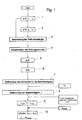
- a compensation current of the drive system is first determined, the at constant engine speed losses occurring, in the way, that at constant engine speed no further power requirement in addition to Compensation current exists. Then the acceleration current is determined which generates a defined (constant) motor acceleration when at constant motor speed occurring losses are compensated. From this acceleration current Finally, the mass moment of inertia is calculated.
- the inventive solution is an analytical method for determining the Mass moment of inertia of an electric motor drive provided, with which determines the mass moment of inertia from the acceleration current, the generates a defined engine speed when at constant engine speed (Engine speed) occurring losses are compensated. That is, at the accelerating current it is a current that only accelerates the Motors causes. Those portions of the current that contribute to the compensation of losses constant engine speed, in particular friction and re-magnetization losses, serve as compensation current separate from the acceleration current considered.
- the compensation current the required to operate the drive at a constant motor speed. This is determined by the drive at least two different engine speeds operated, each constant during a predetermined period are and preferably have the same amount but opposite sign. From this, it is possible to determine the compensation current needed to achieve the Keep motor speed constant at a predetermined value, that is the during operation of the drive with constant engine speed occurring losses fully compensated, so no decrease in engine speed due to Losses occurs.
- the drive for determining the Compensation stream operated at four different engine speeds, each of which has two equal magnitude but opposite sign.
- the electric motor drive is associated with a control device with which the Speed of the drive motor is controlled, then corresponds to the compensation current the pilot control current, with which the speed controller compensates for the losses, the Operation of the drive with constant motor speed occur.
- the operation of a Electromotive drive with speed precontrol is known; this will be For example, refer to the Heidenhain brochure on the iTNC 530 contouring system ( May 2002).
- the drive is preferably at two operated different engine accelerations, each for a given Period are constant and have opposite sign.
- the acceleration current is the one current that is required solely for engine acceleration is, ie the difference of the total required during operation of the electric motor drive Current (total torque current) and that for the compensation of losses required current (compensation current or pilot current).
- acceleration feedforward be used as a constant parameter the ratio of acceleration current and motor acceleration, in particular angular acceleration, indicates.
- the acceleration precontrol is thus a measure of which acceleration current is required to achieve a certain engine acceleration. As described above, this size can be determined when the compensation current is known, ie those parts of the total torque current, the are required to compensate for losses at constant engine acceleration.
- the physical law is used, according to which the acceleration equals the quotient of the acting drive torque (for example the torque) and the Moment of inertia of the drive is.
- the electric drive torque can be here again represent as product of the acceleration current and an engine constant, which in the case of a rotating drive motor is called the torque constant becomes. This results in the representation of the engine acceleration in dependence from the moment of inertia.
- the load moment of inertia can be calculated by the mass moment of inertia of the drive system, the (known, constant) engine mass moment of inertia is deducted. This in turn allows the calculation of the quotient Motor mass moment of inertia and load moment of inertia. This quotient will then by means of an output device, e.g. visually (by means of a screen, a Printer or the like.) Or audible, so that the quotient directly to Is available and can be checked if this as an important parameter for the Controllability of the drive system within a certain, advantageous range of values lies.
- an output device e.g. visually (by means of a screen, a Printer or the like.) Or audible, so that the quotient directly to Is available and can be checked if this as an important parameter for the Controllability of the drive system within a certain, advantageous range of values lies.
- the inventive method is not only suitable for electric motor drives of machines that drive a rotor in the form of a rotor, but also for drives with a linear motor and so-called direct drives.
- an electric motor drive system for a machine tool comprising a drive motor and the drive motor Downstream components, e.g. a clutch, a dome spindle, gear elements and a translationally moving table of the machine tool includes.
- determining the resulting mass moment of inertia of this drive system can be the quotient of the motor mass moment of inertia and the Determine load moment of inertia. Because at the engine mass moment of inertia it is a constant that is known for the particular engine type and usually specified by the manufacturer.
- the drive motor is first accelerated to a first constant speed v 1 and operated at this speed for a predetermined period of time and then braked and accelerated to the opposite, equal velocity -v 1 and at that speed Speed in turn operated for a given period of time. Then the drive is accelerated to a lower speed v 2 and operated in this turn for a predetermined period of time and then braked and accelerated to the opposite same speed -v 2 and operated in this turn for a predetermined period.
- the speeds v 1 , -v 1 are a typical machining feed of the corresponding machine tool, which is operated in each case for a certain period of time with this feed.
- the opposing velocities v 1 , -v 1 each correspond to a feed at the same speed but in the opposite direction.
- FIG. 2 shows the motor speed v of the drive as a function of time t.
- four regions with different constant speeds v 1 , -v 1 , v 2 and -v 2 can be seen , which correspond to the above-described motor speeds.
- the total torque current IM is shown, which is necessary in order to achieve the four different constant engine speeds v 1 , -v 1 , v 2 and -v 2 , and in each case for a defined period of time to maintain a constant level.
- both acceleration components are included, so those power components that cause an acceleration to change the engine speed, and loss ratios that are required to compensate for friction losses and other speed-dependent losses, such as re-magnetization losses.
- the resulting torque current of the drive motor is not equal to zero. So a certain current (compensation current) is required to maintain a constant motor speed and thus a constant feed of the machine tool by compensation of losses.
- the losses occurring during operation of the drive motor at a constant speed and the power required to compensate for these losses can be in one determine next method step 3, by the so-called integral current during evaluated the constant driving phases of the drive motor or the machine tool So, during those phases in which the engine speed or the feed of the machine tool is constant.
- integral current acts it is the total torque current reduced by the proportional component of the current (Noise). This allows the setting 4 of a pilot current, which at constant engine speed occurring friction losses and other, speed-dependent Losses compensated.
- FIG. 3 again shows the engine speed v, the resulting torque current I M, and additionally the acceleration current I B for this second test drive. It is seen that the acceleration current l B is then equal to zero, respectively, when the speed v is constant.
- the acceleration current I B therefore contains only those current components that are required for drive acceleration. The compensation of losses takes place by means of an adjustable by means of the controller of the drive speed feedforward.
- the electromotive drive is operated in the second test drive by the associated control device such that the acceleration in the phases in which set the engine speed to a first value (eg v 1 ) or from a first value (v 1 ) to a second value (-v 1 ) is in each case constant, ie (apart from the respective initial or final phase of the acceleration) has a constant value a or -a.
- step 7 determines the so-called acceleration feedforward FF.
- This is a constant parameter that indicates which acceleration current I B must flow during an acceleration phase in order to achieve a specific angular acceleration ⁇ of the drive motor.
- k T is the torque constant of the drive motor, which is usually specified by the manufacturer of the engine. If this is not the case, then the torque constant k T can be easily calculated, as will be explained below.
- the second formula for the angular acceleration ⁇ k T * I B / J.
- the moment of inertia J is represented as a function of the torque constant k T of the drive motor, which is determined by the design and material selection of the engine and is usually specified by the engine manufacturer, and as a function of the acceleration feedforward FF, which determined in the preceding process steps 1 to 6 has been.
- the quotient of the motor mass moment of inertia and the load mass moment of inertia can now be calculated in a simple manner.
- the total mass moment of inertia of a drive system is composed of the mass moment of inertia J M of the drive motor in the strict sense and the load moment of inertia J L.
- the load moment of inertia J L results in turn additively from contributions which originate from the clutch, dome circulation spindle, gear elements and, for example, a translationally movable table of the machine tool.
- J L J - J M , wherein the engine mass moment of inertia J M is known in the rule.
- this engine mass moment of inertia J M can be determined in the same way as the mass moment of inertia of the drive system as a whole, by carrying out the above-described test drives for the drive motor without load, ie for the rotor (rotor), and evaluating them in the same way as described above ,
- the motor mass moment of inertia is equal to Moment of inertia of the rotor.
- the maximum acceleration a max of the motor is determined.
- a user is then output the desired quotient together with the mass moment of inertia J of the drive system and the maximum acceleration a max of the motor directly on a screen.
- the user can therefore without complex (manually performed) own calculations directly read the quotient J M / J L from the engine moment of inertia and load moment of inertia, with no input data required by the user, not anyway for the operation of the control of the drive system would be required.
- the method according to the invention allows a direct, analytical determination the ratio of motor mass moment of inertia and load mass moment of inertia a drive system of a (tool) machine.
- This quotient is an important aid in the assessment of the machine axis of a machine Machine tool via an (external) adjustment tool.
- he can to adaptive tracking of the controller parameters of a control device of the drive system as well as the pilot control serve. For example, when operating a machine tool found that during the acceleration phases to adjust a required acceleration torque current changes, take place according to the method described above, a redetermination of the acceleration precontrol and the total mass moment of inertia. The control factors then be correspondingly (in particular proportionally) the change in the mass moment of inertia also changed. This will increase the dynamics of the drive system kept constant.
Landscapes
- Physics & Mathematics (AREA)
- General Physics & Mathematics (AREA)
- Control Of Electric Motors In General (AREA)
- Control Of Direct Current Motors (AREA)
- Vibration Prevention Devices (AREA)
Abstract
Description
- Fig. 1 -
- eine schematische Darstellung eines Verfahrens zur Bestimmung des Massenträgheitsmomentes eines elektromotorischen Antriebssystems in einem Flussdiagramm;
- Fig. 2 -
- eine Darstellung des beim Betrieb eines Antriebsmotors einer Werkzeugmaschine auftretenden Stromes;
- Fig. 3 -
- eine Darstellung gemäß Figur 2, wobei zusätzlich der Beschleunigungsstrom dargestellt ist, der nach Kompensation von Verlusten die Motorbeschleunigung bewirkt.
Für die mechanische Motorleistung gilt: Pmech = M * Ω, mit M = kT * J und Ω = 2π * n.
Claims (15)
- Verfahren zur Bestimmung des Massenträgheitsmomentes eines elektromotorischen Antriebssystems einer Maschine, insbesondere einer Werkzeugmaschine, das einen Antriebsmotor und weitere dem Antriebsmotor nachgeordnete Antriebselemente umfasst, bei dema) ein Kompensationsstrom bestimmt wird, der bei konstanter Motorgeschwindigkeit auftretende Verluste kompensiert, so dass die Motorgeschwindigkeit (v) konstant bleibt,b) der Beschleunigungsstrom (lB) bestimmt wird, der eine definierte Motorbeschleunigung (a) erzeugt, wenn die bei konstanter Motorgeschwindigkeit (v) auftretenden Verluste kompensiert sind, undc) aus dem Beschleunigungsstrom (lB) das Massenträgheitsmoment (J) berechnet wird.
- Verfahren nach Anspruch 1, dadurch gekennzeichnet, dass zur Bestimmung des Kompensationsstromes der zum Betrieb des Antriebes bei konstanter Motorgeschwindigkeit (v) erforderliche Strom (lM) bei mindestens einer Motorgeschwindigkeit, vorzugsweise bei mindestens zwei unterschiedlichen Geschwindigkeiten (v1,-v1; v2, -v2), ermittelt wird.
- Verfahren nach Anspruch 2, dadurch gekennzeichnet, dass die mindestens eine Geschwindigkeit (v1, -v1; v2, -v2) während eines vorgebbaren Zeitraumes konstant ist.
- Verfahren nach Anspruch 2 oder 3, dadurch gekennzeichnet, dass die beiden Geschwindigkeiten (v1, -v1; v2, -v2) den gleichen Betrag aber entgegengesetztes Vorzeichen aufweisen.
- Verfahren nach Anspruch 4, dadurch gekennzeichnet, dass der Antriebsmotor zur Bestimmung des Kompensationsstromes nacheinander mit vier unterschiedlichen Geschwindigkeiten (v1, -v1; v2, -v2) betrieben wird, von denen jeweils zwei den gleichen Betrag aber entgegengesetztes Vorzeichen aufweisen.
- Verfahren nach einem der vorhergehenden Ansprüche, dadurch gekennzeichnet, dass die Drehzahl des Antriebsmotors geregelt wird.
- Verfahren nach Anspruch 6, dadurch gekennzeichnet, dass der Kompensationsstrom durch einen Vorsteuerstrom des Drehzahlreglers gebildet wird, mit dem Verluste kompensiert werden, die beim Betrieb des Antriebsmotors mit konstanter Motorgeschwindigkeit (v) auftreten.
- Verfahren nach einem der vorhergehenden Ansprüche, dadurch gekennzeichnet, dass zur Bestimmung des Beschleunigungsstromes (lB) der Antriebsmotor bei zwei unterschiedlichen Beschleunigungen (a, -a) betrieben wird.
- Verfahren nach Anspruch 8, dadurch gekennzeichnet, dass die beiden Beschleunigungen (a, -a) unterschiedliches Vorzeichen aufweisen.
- Verfahren nach Anspruch 8 oder 9, dadurch gekennzeichnet, dass die Beschleunigung (a, -a) jeweils für einen vorgebbaren Zeitraum konstant bleibt.
- Verfahren nach einem der vorhergehenden Ansprüche, dadurch gekennzeichnet, dass der Beschleunigungsstrom (lB) durch die Differenz des totalen Momentenstroms (IM)des Antriebsmotors und des Kompensationsstroms gebildet wird.
- Verfahren nach einem der vorhergehenden Ansprüche, dadurch gekennzeichnet, dass zur Berechnung des Massenträgheitsmomentes (J) aus dem Beschleunigungsstrom (lB) die Motorbeschleunigung (a) einerseits in Abhängigkeit von dem Beschleunigungsstrom (lB) und andererseits in Abhängigkeit von dem Massenträgheitsmoment (J) dargestellt wird und die beiden Formulierungen der Motorbeschleunigung (a) gleichgesetzt werden.
- Verfahren nach einem der vorhergehenden Ansprüche, dadurch gekennzeichnet, dass das Last-Massenträgheitsmoment (JL) des Antriebssystems aus der Differenz des totalen Massenträgheitsmomentes (J) des Antriebssystems und dem Massenträgheitsmoment (JM) des Antriebsmotors bestimmt wird.
- Verfahren nach Anspruch 13, dadurch gekennzeichnet, dass das Verhältnis des Motor-Massenträgheitsmomentes zum Last-Massenträgheitsmoment berechnet wird.
- Verfahren nach Anspruch 14, dadurch gekennzeichnet, dass der Quotient aus Motor-Massenträgheitsmomentes und Last-Massenträgheitsmoment mittels einer Ausgabeeinrichtung angezeigt wird.
Applications Claiming Priority (2)
| Application Number | Priority Date | Filing Date | Title |
|---|---|---|---|
| DE10236847 | 2002-08-08 | ||
| DE10236847A DE10236847A1 (de) | 2002-08-08 | 2002-08-08 | Verfahren zur Bestimmung des Massenträgheitsmomentes eines elektromotorischen Antriebssystems |
Publications (2)
| Publication Number | Publication Date |
|---|---|
| EP1388732A1 true EP1388732A1 (de) | 2004-02-11 |
| EP1388732B1 EP1388732B1 (de) | 2006-06-07 |
Family
ID=30128832
Family Applications (1)
| Application Number | Title | Priority Date | Filing Date |
|---|---|---|---|
| EP03016287A Expired - Lifetime EP1388732B1 (de) | 2002-08-08 | 2003-07-18 | Verfahren zur Bestimmung des Massenträgheitsmomentes eines elektromotorischen Antriebssystems |
Country Status (6)
| Country | Link |
|---|---|
| US (1) | US6998812B2 (de) |
| EP (1) | EP1388732B1 (de) |
| JP (1) | JP4464084B2 (de) |
| AT (1) | ATE329239T1 (de) |
| DE (2) | DE10236847A1 (de) |
| ES (1) | ES2266692T3 (de) |
Cited By (3)
| Publication number | Priority date | Publication date | Assignee | Title |
|---|---|---|---|---|
| EP2290808A1 (de) * | 2009-08-28 | 2011-03-02 | Baumüller Anlagen-Systemtechnik GmbH & Co. KG | Verfahren zur Bestimmung eines Skalierungsfaktors eines elektrischen Antriebssystems sowie zugehörige Einrichtung und zugehöriges elektrisches Antriebssystem |
| EP2565465A1 (de) * | 2011-08-29 | 2013-03-06 | ABB Oy | Verfahren und Vorrichtung zur Bestimmung der Massenänderung eines Lüfterrads |
| CN104792461A (zh) * | 2015-04-23 | 2015-07-22 | 西安交通大学 | 一种回转体高精度转动惯量在线测量方法 |
Families Citing this family (17)
| Publication number | Priority date | Publication date | Assignee | Title |
|---|---|---|---|---|
| JP4565426B2 (ja) * | 2004-09-15 | 2010-10-20 | 株式会社安川電機 | モータ制御装置 |
| NZ554356A (en) | 2004-11-04 | 2010-10-29 | Resmed Ltd | Using motor speed in a pap device to estimate flow |
| US7739764B2 (en) * | 2005-04-27 | 2010-06-22 | Whirlpool Corporation | Method and apparatus for monitoring load size and load imbalance in washing machine |
| CN100516802C (zh) * | 2005-12-16 | 2009-07-22 | 比亚迪股份有限公司 | 汽车惯量的测定方法 |
| BG66064B1 (bg) * | 2006-11-08 | 2010-12-30 | Централна Лаборатория По Мехатроника И Приборостроене - Бан | Манипулатор |
| DE102007020068A1 (de) * | 2007-04-27 | 2008-10-30 | Kaltenbach & Voigt Gmbh | Verfahren und Vorrichtung zur Bestimmung der Motorkonstante eines Elektromotors |
| DE102007040081B4 (de) * | 2007-08-24 | 2010-04-08 | BSH Bosch und Siemens Hausgeräte GmbH | Vorrichtung zum Regeln eines mechanischen Bewegungsverhaltens eines bewegbaren Elements eines Hausgeräts und entsprechendes Verfahren |
| US7627440B2 (en) * | 2007-08-28 | 2009-12-01 | Rockwell Automation Technologies, Inc. | Inertia and load torque estimating method and apparatus |
| KR101671527B1 (ko) | 2010-12-10 | 2016-11-01 | 두산공작기계 주식회사 | 부하 무게에 따른 실시간 서보 모터 제어기 |
| EP2662972B1 (de) * | 2012-05-07 | 2019-12-11 | Kaltenbach & Voigt GmbH | Verfahren zum Betreiben eines Elektromotors eines medizinischen Instruments und zahnmedizinisches System |
| KR101656649B1 (ko) * | 2013-10-11 | 2016-09-09 | 미쓰비시덴키 가부시키가이샤 | 다축 제어 시스템 설정·조정 기능 지원 장치 |
| EP3086468B1 (de) * | 2013-12-20 | 2020-04-15 | FUJI Corporation | Verfahren zur ableitung der drehmomentkonstante von linearmotoren und bewegungssteuerungsverfahren sowie vorrichtung zur ableitung der drehmomentkonstante von linearmotoren und bewegungssteuerungsvorrichtung. |
| DE102015122638A1 (de) * | 2015-12-22 | 2017-06-22 | Schneider Electric Industries Sas | Elektromotorischer Antrieb und Verfahren zum Betreiben eines Motors |
| DE102016005597A1 (de) * | 2016-01-20 | 2017-07-20 | Focke & Co. (Gmbh & Co. Kg) | Verfahren zum Betreiben einer Verpackungsmaschine |
| KR102642664B1 (ko) * | 2017-02-10 | 2024-03-04 | 주식회사 디엔솔루션즈 | 공작기계의 매개변수 설정 방법 및 장치 |
| JP7277260B2 (ja) * | 2019-06-03 | 2023-05-18 | ファナック株式会社 | 振動を抑制するモータ制御装置及び産業機械 |
| CN113979223B (zh) * | 2021-10-29 | 2023-04-07 | 广东韶钢松山股份有限公司 | 一种集卷托盘负载计算方法 |
Citations (4)
| Publication number | Priority date | Publication date | Assignee | Title |
|---|---|---|---|---|
| DE2802224A1 (de) * | 1978-01-19 | 1979-07-26 | Siemens Ag | Schaltungsanordnung zur drehzahlregelung einer von einem elektromotor angetriebenen arbeitsmaschine mit veraenderlicher belastung |
| US4202205A (en) * | 1978-05-26 | 1980-05-13 | MRC Corporation | Integral torquer for mass measurement system |
| US4607408A (en) * | 1983-10-25 | 1986-08-26 | Es swein S.A. | Method for determining a moment of inertia of clothes in a washing and/or drying machine |
| FR2631988A1 (fr) * | 1988-05-31 | 1989-12-01 | Ciapem | Perfectionnements a un lave-linge ou seche-linge a determination automatique de la charge de linge introduite dans la machine |
Family Cites Families (12)
| Publication number | Priority date | Publication date | Assignee | Title |
|---|---|---|---|---|
| US4649328A (en) * | 1985-06-26 | 1987-03-10 | General Electric Co. | Method for automatic speed loop tune-up in a machine drive |
| US4827197A (en) * | 1987-05-22 | 1989-05-02 | Beckman Instruments, Inc. | Method and apparatus for overspeed protection for high speed centrifuges |
| JP2892802B2 (ja) * | 1990-09-21 | 1999-05-17 | 株式会社日立製作所 | 電動機の速度制御装置 |
| JP3235242B2 (ja) * | 1992-11-30 | 2001-12-04 | 株式会社明電舎 | 2慣性ねじり振動系の速度制御におけるイナーシャ推定方法 |
| JPH08140386A (ja) * | 1994-11-08 | 1996-05-31 | Fanuc Ltd | サーボモータのイナーシャ推定方法 |
| EP0827265B1 (de) | 1995-05-17 | 2002-04-10 | Kabushiki Kaisha Yaskawa Denki | Vorrichtung zur bestimmung von regelungskonstanten |
| US6144181A (en) * | 1998-09-21 | 2000-11-07 | Rockwell Technologies, Llc | Method and apparatus for reducing resonance in a dual inertia system |
| US6470225B1 (en) * | 1999-04-16 | 2002-10-22 | Siemens Energy & Automation, Inc. | Method and apparatus for automatically tuning feedforward parameters |
| JP2001169584A (ja) * | 1999-09-28 | 2001-06-22 | Seiko Epson Corp | プリンタ用モータの制御装置およびその制御方法ならびに制御プログラムを記録した記録媒体 |
| JP3731060B2 (ja) * | 2000-11-14 | 2006-01-05 | 株式会社日立製作所 | イナーシャ演算方法及び電動機のドライブ装置 |
| JP2003210888A (ja) * | 2002-01-25 | 2003-07-29 | Sharp Corp | 洗濯機の布量検知方法、洗濯機の布量検知装置及び洗濯機 |
| KR100494919B1 (ko) * | 2003-03-05 | 2005-06-13 | 현대자동차주식회사 | 병렬형 하이브리드 전기자동차의 모터 제어방법 및 그제어장치 |
-
2002
- 2002-08-08 DE DE10236847A patent/DE10236847A1/de not_active Withdrawn
-
2003
- 2003-07-11 JP JP2003195611A patent/JP4464084B2/ja not_active Expired - Fee Related
- 2003-07-18 DE DE50303654T patent/DE50303654D1/de not_active Expired - Lifetime
- 2003-07-18 ES ES03016287T patent/ES2266692T3/es not_active Expired - Lifetime
- 2003-07-18 AT AT03016287T patent/ATE329239T1/de not_active IP Right Cessation
- 2003-07-18 EP EP03016287A patent/EP1388732B1/de not_active Expired - Lifetime
- 2003-08-08 US US10/637,716 patent/US6998812B2/en not_active Expired - Lifetime
Patent Citations (4)
| Publication number | Priority date | Publication date | Assignee | Title |
|---|---|---|---|---|
| DE2802224A1 (de) * | 1978-01-19 | 1979-07-26 | Siemens Ag | Schaltungsanordnung zur drehzahlregelung einer von einem elektromotor angetriebenen arbeitsmaschine mit veraenderlicher belastung |
| US4202205A (en) * | 1978-05-26 | 1980-05-13 | MRC Corporation | Integral torquer for mass measurement system |
| US4607408A (en) * | 1983-10-25 | 1986-08-26 | Es swein S.A. | Method for determining a moment of inertia of clothes in a washing and/or drying machine |
| FR2631988A1 (fr) * | 1988-05-31 | 1989-12-01 | Ciapem | Perfectionnements a un lave-linge ou seche-linge a determination automatique de la charge de linge introduite dans la machine |
Cited By (7)
| Publication number | Priority date | Publication date | Assignee | Title |
|---|---|---|---|---|
| EP2290808A1 (de) * | 2009-08-28 | 2011-03-02 | Baumüller Anlagen-Systemtechnik GmbH & Co. KG | Verfahren zur Bestimmung eines Skalierungsfaktors eines elektrischen Antriebssystems sowie zugehörige Einrichtung und zugehöriges elektrisches Antriebssystem |
| EP2565465A1 (de) * | 2011-08-29 | 2013-03-06 | ABB Oy | Verfahren und Vorrichtung zur Bestimmung der Massenänderung eines Lüfterrads |
| CN102966582A (zh) * | 2011-08-29 | 2013-03-13 | Abb公司 | 用于确定风机叶轮的质量变化的方法和设备 |
| US9021876B2 (en) | 2011-08-29 | 2015-05-05 | Abb Oy | Method and apparatus for determining change in mass of fan impeller |
| CN102966582B (zh) * | 2011-08-29 | 2015-09-30 | Abb技术有限公司 | 用于确定风机叶轮的质量变化的方法和设备 |
| CN104792461A (zh) * | 2015-04-23 | 2015-07-22 | 西安交通大学 | 一种回转体高精度转动惯量在线测量方法 |
| CN104792461B (zh) * | 2015-04-23 | 2017-06-06 | 西安交通大学 | 一种回转体高精度转动惯量在线测量方法 |
Also Published As
| Publication number | Publication date |
|---|---|
| JP2004069689A (ja) | 2004-03-04 |
| ATE329239T1 (de) | 2006-06-15 |
| ES2266692T3 (es) | 2007-03-01 |
| EP1388732B1 (de) | 2006-06-07 |
| DE50303654D1 (de) | 2006-07-20 |
| US20040100219A1 (en) | 2004-05-27 |
| DE10236847A1 (de) | 2004-02-26 |
| JP4464084B2 (ja) | 2010-05-19 |
| US6998812B2 (en) | 2006-02-14 |
Similar Documents
| Publication | Publication Date | Title |
|---|---|---|
| EP1388732B1 (de) | Verfahren zur Bestimmung des Massenträgheitsmomentes eines elektromotorischen Antriebssystems | |
| DE2452756C3 (de) | Zuführungsvorrichtung für eine in eine Druckmaschine einlaufende Materialbahn | |
| DE69912028T2 (de) | Vorrichtung und Verfahren zur Erzeugung eines gewünschten Rückstellmomentes für die Servolenkung eines Kraftfahrzeuges | |
| DE102013109596B4 (de) | Motorregelsystem zum Korrigieren von Spiel | |
| EP0896263B1 (de) | Verfahren und Schaltungsanordnung zur Ermittlung optimaler Reglerparameter für eine Drehzahlregelung | |
| DE102015107583A1 (de) | Positionierantrieb sowie Verfahren zum Positionieren eines Abtriebselements | |
| EP3176657A1 (de) | Bestimmung der steifigkeit eines antriebsstranges einer maschine, insbesondere einer werkzeug- oder produktionsmaschine | |
| DE102009038155B4 (de) | Servomotorsteuergerät | |
| DE4129539C2 (de) | Drehzahlregelkreis für einen Elektromotor | |
| DE102011102453B4 (de) | Verfahren und Vorrichtung zur Bestimmung einer Reibkraftamplitude in einem Lenksystem | |
| DE69309803T2 (de) | Verfahren zur regelung der lage einer spindel | |
| DE3726024A1 (de) | Vorrichtung zum umwuchtausgleich in zwei ebenen an einem rotor, insbesondere kraftfahrzeugrad | |
| WO2024235781A1 (de) | Verfahren zum betreiben eines elektromotors für ein elektrofahrrad, antriebssystem und elektrofahrrad | |
| EP0206984A2 (de) | Verfahren und Vorrichtung zur Regelung der Drehzahl einer Spindel einer Zahnradbearbeitungsmaschine | |
| DE1068035B (de) | Anordnung zur Drehzahlregelung von motorisch angetriebenen Teilen auf konstante Drehzahl- oder Geschwindigkeitsverhältnisse, insbesondere für Mehrmotorenantriebe | |
| CH660937A5 (de) | Einrichtung zur steuerung einer mit vibrationen behafteten maschine. | |
| EP2290808B1 (de) | Verfahren zur Bestimmung eines Skalierungsfaktors eines elektrischen Antriebssystems sowie zugehörige Einrichtung und zugehöriges elektrisches Antriebssystem | |
| EP1005147A2 (de) | Verfahren und Schaltungsanordnung zur Ermittlung einer optimalen Verstärkung des Integrators eines Drehzahlreglers | |
| DE19730851B4 (de) | Verfahren zur Simulierung von Trägheitskräften mit Hilfe eines Dynamometers | |
| DE60209894T2 (de) | Verfahren und vorrichtung zur winkelgeschwindigkeitssteuerung einer schwachgedämpften elektromechanischen kette | |
| EP0704962B1 (de) | Regelung des relativen Gleichlaufs mechanisch gekoppelter Werkzeugmaschinenachsen | |
| DE2749505C2 (de) | Sollwertkaskade | |
| AT522260B1 (de) | Verfahren und Regelungseinrichtung zur Regelung einer Drehzahl | |
| DE2805989C2 (de) | Selbsttätige Steuerung für den Schaltmotor von elektromechanischen, selbsteinspielenden Waagen | |
| DE102016207333A1 (de) | Verfahren und Vorrichtung zur Regelung einer elektrischen Maschine während eines Impulsstartes eines Verbrennungsmotors |
Legal Events
| Date | Code | Title | Description |
|---|---|---|---|
| PUAI | Public reference made under article 153(3) epc to a published international application that has entered the european phase |
Free format text: ORIGINAL CODE: 0009012 |
|
| AK | Designated contracting states |
Kind code of ref document: A1 Designated state(s): AT BE BG CH CY CZ DE DK EE ES FI FR GB GR HU IE IT LI LU MC NL PT RO SE SI SK TR |
|
| AX | Request for extension of the european patent |
Extension state: AL LT LV MK |
|
| 17P | Request for examination filed |
Effective date: 20040811 |
|
| 17Q | First examination report despatched |
Effective date: 20040910 |
|
| AKX | Designation fees paid |
Designated state(s): AT BE BG CH CY CZ DE DK EE ES FI FR GB GR HU IE IT LI LU MC NL PT RO SE SI SK TR |
|
| GRAP | Despatch of communication of intention to grant a patent |
Free format text: ORIGINAL CODE: EPIDOSNIGR1 |
|
| GRAS | Grant fee paid |
Free format text: ORIGINAL CODE: EPIDOSNIGR3 |
|
| GRAA | (expected) grant |
Free format text: ORIGINAL CODE: 0009210 |
|
| AK | Designated contracting states |
Kind code of ref document: B1 Designated state(s): AT BE BG CH CY CZ DE DK EE ES FI FR GB GR HU IE IT LI LU MC NL PT RO SE SI SK TR |
|
| PG25 | Lapsed in a contracting state [announced via postgrant information from national office to epo] |
Ref country code: CZ Free format text: LAPSE BECAUSE OF FAILURE TO SUBMIT A TRANSLATION OF THE DESCRIPTION OR TO PAY THE FEE WITHIN THE PRESCRIBED TIME-LIMIT Effective date: 20060607 Ref country code: FI Free format text: LAPSE BECAUSE OF FAILURE TO SUBMIT A TRANSLATION OF THE DESCRIPTION OR TO PAY THE FEE WITHIN THE PRESCRIBED TIME-LIMIT Effective date: 20060607 Ref country code: SK Free format text: LAPSE BECAUSE OF FAILURE TO SUBMIT A TRANSLATION OF THE DESCRIPTION OR TO PAY THE FEE WITHIN THE PRESCRIBED TIME-LIMIT Effective date: 20060607 Ref country code: NL Free format text: LAPSE BECAUSE OF FAILURE TO SUBMIT A TRANSLATION OF THE DESCRIPTION OR TO PAY THE FEE WITHIN THE PRESCRIBED TIME-LIMIT Effective date: 20060607 Ref country code: SI Free format text: LAPSE BECAUSE OF FAILURE TO SUBMIT A TRANSLATION OF THE DESCRIPTION OR TO PAY THE FEE WITHIN THE PRESCRIBED TIME-LIMIT Effective date: 20060607 Ref country code: IE Free format text: LAPSE BECAUSE OF FAILURE TO SUBMIT A TRANSLATION OF THE DESCRIPTION OR TO PAY THE FEE WITHIN THE PRESCRIBED TIME-LIMIT Effective date: 20060607 Ref country code: RO Free format text: LAPSE BECAUSE OF FAILURE TO SUBMIT A TRANSLATION OF THE DESCRIPTION OR TO PAY THE FEE WITHIN THE PRESCRIBED TIME-LIMIT Effective date: 20060607 |
|
| REG | Reference to a national code |
Ref country code: GB Ref legal event code: FG4D Free format text: NOT ENGLISH |
|
| REG | Reference to a national code |
Ref country code: CH Ref legal event code: EP |
|
| GBT | Gb: translation of ep patent filed (gb section 77(6)(a)/1977) |
Effective date: 20060607 |
|
| REG | Reference to a national code |
Ref country code: IE Ref legal event code: FG4D Free format text: LANGUAGE OF EP DOCUMENT: GERMAN |
|
| REF | Corresponds to: |
Ref document number: 50303654 Country of ref document: DE Date of ref document: 20060720 Kind code of ref document: P |
|
| PG25 | Lapsed in a contracting state [announced via postgrant information from national office to epo] |
Ref country code: MC Free format text: LAPSE BECAUSE OF NON-PAYMENT OF DUE FEES Effective date: 20060731 Ref country code: BE Free format text: LAPSE BECAUSE OF NON-PAYMENT OF DUE FEES Effective date: 20060731 |
|
| PG25 | Lapsed in a contracting state [announced via postgrant information from national office to epo] |
Ref country code: DK Free format text: LAPSE BECAUSE OF FAILURE TO SUBMIT A TRANSLATION OF THE DESCRIPTION OR TO PAY THE FEE WITHIN THE PRESCRIBED TIME-LIMIT Effective date: 20060907 Ref country code: SE Free format text: LAPSE BECAUSE OF FAILURE TO SUBMIT A TRANSLATION OF THE DESCRIPTION OR TO PAY THE FEE WITHIN THE PRESCRIBED TIME-LIMIT Effective date: 20060907 |
|
| PG25 | Lapsed in a contracting state [announced via postgrant information from national office to epo] |
Ref country code: PT Free format text: LAPSE BECAUSE OF FAILURE TO SUBMIT A TRANSLATION OF THE DESCRIPTION OR TO PAY THE FEE WITHIN THE PRESCRIBED TIME-LIMIT Effective date: 20061107 |
|
| ET | Fr: translation filed | ||
| NLV1 | Nl: lapsed or annulled due to failure to fulfill the requirements of art. 29p and 29m of the patents act | ||
| REG | Reference to a national code |
Ref country code: IE Ref legal event code: FD4D |
|
| REG | Reference to a national code |
Ref country code: ES Ref legal event code: FG2A Ref document number: 2266692 Country of ref document: ES Kind code of ref document: T3 |
|
| PLBE | No opposition filed within time limit |
Free format text: ORIGINAL CODE: 0009261 |
|
| STAA | Information on the status of an ep patent application or granted ep patent |
Free format text: STATUS: NO OPPOSITION FILED WITHIN TIME LIMIT |
|
| 26N | No opposition filed |
Effective date: 20070308 |
|
| PG25 | Lapsed in a contracting state [announced via postgrant information from national office to epo] |
Ref country code: AT Free format text: LAPSE BECAUSE OF NON-PAYMENT OF DUE FEES Effective date: 20060718 |
|
| BERE | Be: lapsed |
Owner name: DR. JOHANNES HEIDENHAIN G.M.B.H. Effective date: 20060731 |
|
| REG | Reference to a national code |
Ref country code: CH Ref legal event code: PL |
|
| PG25 | Lapsed in a contracting state [announced via postgrant information from national office to epo] |
Ref country code: CH Free format text: LAPSE BECAUSE OF NON-PAYMENT OF DUE FEES Effective date: 20070731 Ref country code: GR Free format text: LAPSE BECAUSE OF FAILURE TO SUBMIT A TRANSLATION OF THE DESCRIPTION OR TO PAY THE FEE WITHIN THE PRESCRIBED TIME-LIMIT Effective date: 20060908 Ref country code: LI Free format text: LAPSE BECAUSE OF NON-PAYMENT OF DUE FEES Effective date: 20070731 |
|
| PG25 | Lapsed in a contracting state [announced via postgrant information from national office to epo] |
Ref country code: EE Free format text: LAPSE BECAUSE OF FAILURE TO SUBMIT A TRANSLATION OF THE DESCRIPTION OR TO PAY THE FEE WITHIN THE PRESCRIBED TIME-LIMIT Effective date: 20060607 Ref country code: BG Free format text: LAPSE BECAUSE OF FAILURE TO SUBMIT A TRANSLATION OF THE DESCRIPTION OR TO PAY THE FEE WITHIN THE PRESCRIBED TIME-LIMIT Effective date: 20060907 |
|
| PG25 | Lapsed in a contracting state [announced via postgrant information from national office to epo] |
Ref country code: HU Free format text: LAPSE BECAUSE OF FAILURE TO SUBMIT A TRANSLATION OF THE DESCRIPTION OR TO PAY THE FEE WITHIN THE PRESCRIBED TIME-LIMIT Effective date: 20061208 Ref country code: LU Free format text: LAPSE BECAUSE OF NON-PAYMENT OF DUE FEES Effective date: 20060718 Ref country code: TR Free format text: LAPSE BECAUSE OF FAILURE TO SUBMIT A TRANSLATION OF THE DESCRIPTION OR TO PAY THE FEE WITHIN THE PRESCRIBED TIME-LIMIT Effective date: 20060607 |
|
| PG25 | Lapsed in a contracting state [announced via postgrant information from national office to epo] |
Ref country code: CY Free format text: LAPSE BECAUSE OF FAILURE TO SUBMIT A TRANSLATION OF THE DESCRIPTION OR TO PAY THE FEE WITHIN THE PRESCRIBED TIME-LIMIT Effective date: 20060607 |
|
| PGFP | Annual fee paid to national office [announced via postgrant information from national office to epo] |
Ref country code: FR Payment date: 20140721 Year of fee payment: 12 |
|
| REG | Reference to a national code |
Ref country code: FR Ref legal event code: ST Effective date: 20160331 |
|
| PG25 | Lapsed in a contracting state [announced via postgrant information from national office to epo] |
Ref country code: FR Free format text: LAPSE BECAUSE OF NON-PAYMENT OF DUE FEES Effective date: 20150731 |
|
| PGFP | Annual fee paid to national office [announced via postgrant information from national office to epo] |
Ref country code: GB Payment date: 20170719 Year of fee payment: 15 Ref country code: IT Payment date: 20170728 Year of fee payment: 15 Ref country code: ES Payment date: 20170825 Year of fee payment: 15 |
|
| GBPC | Gb: european patent ceased through non-payment of renewal fee |
Effective date: 20180718 |
|
| PG25 | Lapsed in a contracting state [announced via postgrant information from national office to epo] |
Ref country code: GB Free format text: LAPSE BECAUSE OF NON-PAYMENT OF DUE FEES Effective date: 20180718 |
|
| PG25 | Lapsed in a contracting state [announced via postgrant information from national office to epo] |
Ref country code: IT Free format text: LAPSE BECAUSE OF NON-PAYMENT OF DUE FEES Effective date: 20180718 |
|
| REG | Reference to a national code |
Ref country code: ES Ref legal event code: FD2A Effective date: 20190917 |
|
| PG25 | Lapsed in a contracting state [announced via postgrant information from national office to epo] |
Ref country code: ES Free format text: LAPSE BECAUSE OF NON-PAYMENT OF DUE FEES Effective date: 20180719 |
|
| PGFP | Annual fee paid to national office [announced via postgrant information from national office to epo] |
Ref country code: DE Payment date: 20190719 Year of fee payment: 17 |
|
| REG | Reference to a national code |
Ref country code: DE Ref legal event code: R119 Ref document number: 50303654 Country of ref document: DE |
|
| PG25 | Lapsed in a contracting state [announced via postgrant information from national office to epo] |
Ref country code: DE Free format text: LAPSE BECAUSE OF NON-PAYMENT OF DUE FEES Effective date: 20210202 |