EP1388617A1 - Ablaufgarnitur - Google Patents
Ablaufgarnitur Download PDFInfo
- Publication number
- EP1388617A1 EP1388617A1 EP03016124A EP03016124A EP1388617A1 EP 1388617 A1 EP1388617 A1 EP 1388617A1 EP 03016124 A EP03016124 A EP 03016124A EP 03016124 A EP03016124 A EP 03016124A EP 1388617 A1 EP1388617 A1 EP 1388617A1
- Authority
- EP
- European Patent Office
- Prior art keywords
- drain
- bolt
- valve
- outlet
- fitting according
- Prior art date
- Legal status (The legal status is an assumption and is not a legal conclusion. Google has not performed a legal analysis and makes no representation as to the accuracy of the status listed.)
- Granted
Links
- 238000007789 sealing Methods 0.000 claims description 2
- 230000006835 compression Effects 0.000 claims 1
- 238000007906 compression Methods 0.000 claims 1
- 239000002699 waste material Substances 0.000 description 11
- 101150114468 TUB1 gene Proteins 0.000 description 4
- 239000012530 fluid Substances 0.000 description 3
- 230000007246 mechanism Effects 0.000 description 3
- 238000010276 construction Methods 0.000 description 2
- 238000004519 manufacturing process Methods 0.000 description 2
- 238000000034 method Methods 0.000 description 2
- 230000008878 coupling Effects 0.000 description 1
- 238000010168 coupling process Methods 0.000 description 1
- 238000005859 coupling reaction Methods 0.000 description 1
- 239000007788 liquid Substances 0.000 description 1
- 239000000463 material Substances 0.000 description 1
- 238000000465 moulding Methods 0.000 description 1
- 238000005580 one pot reaction Methods 0.000 description 1
- XLYOFNOQVPJJNP-UHFFFAOYSA-N water Substances O XLYOFNOQVPJJNP-UHFFFAOYSA-N 0.000 description 1
Images



Classifications
-
- E—FIXED CONSTRUCTIONS
- E03—WATER SUPPLY; SEWERAGE
- E03C—DOMESTIC PLUMBING INSTALLATIONS FOR FRESH WATER OR WASTE WATER; SINKS
- E03C1/00—Domestic plumbing installations for fresh water or waste water; Sinks
- E03C1/12—Plumbing installations for waste water; Basins or fountains connected thereto; Sinks
- E03C1/22—Outlet devices mounted in basins, baths, or sinks
- E03C1/23—Outlet devices mounted in basins, baths, or sinks with mechanical closure mechanisms
- E03C1/2304—Outlet devices mounted in basins, baths, or sinks with mechanical closure mechanisms the actuation force being transmitted to the plug via flexible elements, e.g. chain, Bowden cable
-
- A—HUMAN NECESSITIES
- A61—MEDICAL OR VETERINARY SCIENCE; HYGIENE
- A61H—PHYSICAL THERAPY APPARATUS, e.g. DEVICES FOR LOCATING OR STIMULATING REFLEX POINTS IN THE BODY; ARTIFICIAL RESPIRATION; MASSAGE; BATHING DEVICES FOR SPECIAL THERAPEUTIC OR HYGIENIC PURPOSES OR SPECIFIC PARTS OF THE BODY
- A61H33/00—Bathing devices for special therapeutic or hygienic purposes
- A61H33/60—Components specifically designed for the therapeutic baths of groups A61H33/00
- A61H33/6068—Outlet from the bath
- A61H33/6073—Intake mouths for recirculation of fluid in whirlpool baths
- A61H33/6078—Combined with waste outlets
-
- E—FIXED CONSTRUCTIONS
- E03—WATER SUPPLY; SEWERAGE
- E03C—DOMESTIC PLUMBING INSTALLATIONS FOR FRESH WATER OR WASTE WATER; SINKS
- E03C1/00—Domestic plumbing installations for fresh water or waste water; Sinks
- E03C1/12—Plumbing installations for waste water; Basins or fountains connected thereto; Sinks
- E03C1/22—Outlet devices mounted in basins, baths, or sinks
- E03C1/23—Outlet devices mounted in basins, baths, or sinks with mechanical closure mechanisms
- E03C2001/2315—Outlet devices mounted in basins, baths, or sinks with mechanical closure mechanisms the actuation force created by a turning movement of a handle
Definitions
- the present invention relates to a waste fitting, in particular for a Tub with whirlpool according to the preamble of claim 1.
- an actuating mechanism was used in which is split over a clutch a Bowden cable into two Bowden cables to each with a Bowden cable the valve on the drain and with the second Bowden cable to operate a closure element at the other terminal.
- the actuating unit has an actuating element for simultaneous Actuation of the valve on the drain and the closure element on the further connection. This reduces the number of required components, because the clutch for separate actuation of the closure element and the Valve can be omitted and the actuator, the function of this coupling takes over and no separate actuators must be provided. Furthermore, the waste set can be made compact, since by the actuator both the valve and the closure element adjacent to each other may be arranged to be operated simultaneously.
- the actuating element designed as a rotatably mounted bolt.
- Most appropriate controls are placed on an overflow and are equipped with a Bowden cable, which then attack the lever can.
- a structurally simple closure with only a few components is obtained when the bolt carries at one end a rotary valve in which one with the connector connectable flow channel is formed.
- the actuating element engages directly on the rotary valve, leaving no additional elements must be provided.
- the rotary valve is preferable rotatably mounted in a sealing element, set in the pop-up waste is.
- the seal on the rotary valve can be such take place that the rotary valve arranged in the axial direction of the bolt Inlet and a radially arranged outlet, wherein the Outlet of a bottom-side opening in the valve is opposite. Thereby a fluid flows automatically with a corresponding rotation of the rotary valve down from.
- On the bolt may further be fixed a lever by means of which the valve on Sequence is actuated. By turning the bolt, the valve can be over the Move lever linearly.
- the waste fitting bolts and / or corresponding Housing parts made of plastic.
- the waste set be formed in several parts and a drain pot and at least one flow element exhibit. This also allows the production of more complicated forms of Waste.
- a drain fitting is mounted on a trough 1, the bottom side a drain opening 2 and on a side wall has an opening 16 as an overflow.
- a drain 3 is mounted, which closable by means of a valve 4 is.
- the valve 4 is made of a cap 5 and a fixed thereto Seal 6 and a pin member 7, in which a screw 8 is screwed formed.
- the pin 7 is mounted in a guide 70 and movable in the vertical direction, thus the process 3 are opened and closed via the valve 4 can.
- the drain fitting further comprises a flow element 10, at its upper edge a seal 9 is provided.
- the flow element 10 is above the seal 9 clamped at the drain opening 2 set.
- the drain fitting has a multi-part housing made of plastic a drain pot 33, on which the flow element 10 is fixed sealed.
- the flow element 10 is by means of a latching connection in the drain pot 33 plugged.
- the drain pot 33 comprises a siphon-like curve 41, which in a pipe section 34 opens, which is connectable to a drain pipe.
- the siphon-like Diverter 41 provides an odor trap.
- connection 11 is provided on the flow element 10, which has a Nut 12 defines a tube 13 to an overflow clamping.
- the tube 13 is connected via a bow with a pipe 14, which is provided with an overflow element 15 communicates.
- the overflow element 15 is at the opening 16 of the tub 1, which is optically hidden by a knob 17. With appropriate Level can be a fluid from the tub 1 through the overflow element 15th flow out through the tube 13.
- the knob 17 is rotated, which has a Bowden cable not shown connected to a rotatable pin 20 is.
- the bolt 20 comprises a lever 19, which with the Bowden cable is connected.
- the bolt 20 is opposite in one direction biased towards the tensile load, so that by means of the knob 17 of the bolt 20 is rotatable in both directions.
- a recess 21 is provided, in which a holding portion of a Lever 24 is fixed.
- the lever 24 is located on the underside of the screw eighth on, so that by rotation of the bolt 20, the valve 4 is lowered and raised can be to open the flow 3 and close.
- a tapered portion 22 is formed on the bolt 20, on which protruding Moldings 32 are formed.
- a rotary valve 23rd attached, which is mounted adjacent to another terminal 26.
- the connection 26 is connected to a circulating piping system in which over a pump sucked water from the tub 1 and through one or more nozzles is returned to the wall, in particular for massage purposes, if necessary also enriched with air.
- the rotary valve 23 is rotatably held in a seal 25, which has projections 36 engages in grooves on the flow element 10 and thus rotatably mounted.
- the seal 25 is provided in a lower region with a recess 35, which is aligned with a drain channel 29 in the flow element 10.
- a grommet 27 is fixed on the connection 26 via a retaining ring 28, which is connected to the circulating system.
- the rotary valve 25 has a in the axial direction of the bolt 20 arranged inlet 30 and one in radial Direction of the rotary valve 23 arranged outlet 40.
- the rotary valve 25 is thereby cup-shaped and includes a receptacle 37 with grooves 38 for engagement with the tapered portion 22 of the bolt 20.
- a slot 39 recessed, so that the walls of the rotary valve 23 a certain Have elasticity and the rotary valve 23 with a slight interference fit on the section 22 can be postponed.
- the drain pot 33, the flow element 10 and the bolt 20 and the rotary valve 23 formed of plastic. Depending on requirements, other materials can be used.
- the waste set according to the invention is suitable for any application, in the two ports simultaneously closed by means of an actuating element need to be, for example, in whirlpools.
- An overflow is not mandatory necessary, but appropriate for use on a tub 1.
- the mechanical operation via the knob 17 is just one of many ways to move the actuator via an adjustment mechanism. Also other mechanisms such as linkages, chains, etc. can be used.
- the illustrated rotary valve 23 allows a simple way the closure of the terminal 26.
- other valves for example come with plug used that can be moved over the bolt 20 are.
Landscapes
- Health & Medical Sciences (AREA)
- Engineering & Computer Science (AREA)
- Public Health (AREA)
- Life Sciences & Earth Sciences (AREA)
- Physical Education & Sports Medicine (AREA)
- General Health & Medical Sciences (AREA)
- Environmental & Geological Engineering (AREA)
- Water Supply & Treatment (AREA)
- Epidemiology (AREA)
- Pain & Pain Management (AREA)
- Mechanical Engineering (AREA)
- Rehabilitation Therapy (AREA)
- Animal Behavior & Ethology (AREA)
- Hydrology & Water Resources (AREA)
- Veterinary Medicine (AREA)
- Mechanically-Actuated Valves (AREA)
- Sink And Installation For Waste Water (AREA)
- Percussion Or Vibration Massage (AREA)
- Domestic Plumbing Installations (AREA)
- Separation Using Semi-Permeable Membranes (AREA)
- Processes For Solid Components From Exhaust (AREA)
Abstract
Description
- Fig. 1
- eine geschnittene Ansicht eines Ausführungsbeispiels einer erfindungsgemäßen Ablaufgarnitur im montierten Zustand;
- Fig. 2
- eine perspektivische Ansicht der Ablaufgarnitur der Fig. 2 im Bereich des Bolzens;
- Fig. 3
- eine geschnittene Draufsicht der Ablaufgarnitur der Fig. 1;
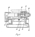
- Fig. 4
- eine geschnittene Seitenansicht der Ablaufgarnitur der Fig. 1;
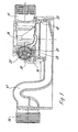
- Fig. 5
- eine geschnittene Rückansicht der Ablaufgarnitur der Fig. 1, und
- Fig. 6A u. 6B
- zwei perspektivische Ansichten des Drehventils der Ablaufgarnitur der Fig. 1.
Claims (10)
- Ablaufgarnitur, insbesondere für eine Wanne (1) mit Whirlpool, mit einem verschließbaren Ablauf (3), der über einen Ablaufkopf (33) mit einem Abflussrohr verbindbar ist, und an einer Ablauföffnung (2) einer Wanne (1) montierbar ist, und einer Betätigungseinheit (17, 18, 20, 24), mittels der ein Ventil (4) am Ablauf (2) geöffnet und verschlossen werden kann, und mittels der ein mit dem Ablauftopf (33) verbundener weiterer Anschluss (26) über ein Verschlusselement (23) geöffnet und verschlossen werden kann, dadurch gekennzeichnet, dass die Betätigungseinheit ein Betätigungselement (20) zur gleichzeitigen Betätigung des Ventils (4) am Ablauf (3) und des Verschlusselementes (23) an dem weiteren Anschluss (26) aufweist.
- Ablaufgarnitur nach Anspruch 1, dadurch gekennzeichnet, dass das Betätigungselement (20) als drehbar gelagerter Bolzen ausgebildet ist.
- Ablaufgarnitur nach Anspruch 1 oder 2, dadurch gekennzeichnet, dass an dem Bolzen (20) ein Hebel (19) vorgesehen ist, der mittels eines Zug- und Druckelementes bewegbar ist.
- Ablaufgarnitur nach einem der Ansprüche 1 bis 3, dadurch gekennzeichnet, dass der Bolzen (20) an einem Ende ein Drehventil (23) trägt, in dem ein mit dem Anschluss (26) verbindbarer Durchflusskanal (30) ausgebildet ist.
- Ablaufgarnitur nach Anspruch 4, dadurch gekennzeichnet, dass das Drehventil (23) in einem Dichtelement (25) drehbar gelagert ist.
- Ablaufgarnitur nach Anspruch 4 oder 5, dadurch gekennzeichnet, dass das Drehventil (23) drehfest auf den Bolzen (20) aufgesteckt ist.
- Ablaufgarnitur nach einem der Ansprüche 4 bis 6, dadurch gekennzeichnet, dass das Drehventil (23) einen in axialer Richtung des Bolzens (20) angeordneten Einlass und einen in radialer Richtung angeordneten Auslass aufweist.
- Ablaufgarnitur nach einem der Ansprüche 1 bis 7, dadurch gekennzeichnet, dass an dem Bolzen (20) ein Hebel (24) festgelegt ist, mittels dem das Ventil (4) am Ablauf (3) betätigbar ist.
- Ablaufgarnitur nach einem der Ansprüche 1 bis 8, dadurch gekennzeichnet, dass der Bolzen (20) und/oder das Drehventil (23) aus Kunststoff hergestellt ist.
- Ablaufgarnitur nach einem der Ansprüche 1 bis 9, dadurch gekennzeichnet, dass ein Gehäuse der Ablaufgarnitur mehrteilig mit einem Ablauftopf (33) und mindestens einem Durchflusselement (10) ausgebildet ist.
Applications Claiming Priority (2)
| Application Number | Priority Date | Filing Date | Title |
|---|---|---|---|
| DE20212291U DE20212291U1 (de) | 2002-08-09 | 2002-08-09 | Ablaufgarnitur |
| DE20212291U | 2002-08-09 |
Publications (2)
| Publication Number | Publication Date |
|---|---|
| EP1388617A1 true EP1388617A1 (de) | 2004-02-11 |
| EP1388617B1 EP1388617B1 (de) | 2006-09-13 |
Family
ID=29796694
Family Applications (1)
| Application Number | Title | Priority Date | Filing Date |
|---|---|---|---|
| EP03016124A Expired - Lifetime EP1388617B1 (de) | 2002-08-09 | 2003-07-16 | Ablaufgarnitur |
Country Status (4)
| Country | Link |
|---|---|
| EP (1) | EP1388617B1 (de) |
| AT (1) | ATE339557T1 (de) |
| DE (2) | DE20212291U1 (de) |
| ES (1) | ES2272860T3 (de) |
Citations (4)
| Publication number | Priority date | Publication date | Assignee | Title |
|---|---|---|---|---|
| DE2308920A1 (de) * | 1971-02-05 | 1974-09-05 | Hans Schumacher | Einrichtung an einer unterwassermassage-vorrichtung fuer badewannen |
| GB2217986A (en) * | 1988-04-05 | 1989-11-08 | John Murfin | Whirlpool/spa bath drainage valve |
| EP0410944A1 (de) * | 1989-07-24 | 1991-01-30 | Smalteria Viterbese S.P.A. | Abflussvorrichtung, insbesondere für Wasserstrahlmassagebecken |
| EP0421520A2 (de) * | 1989-10-03 | 1991-04-10 | TEUCO GUZZINI S.r.l. | Ablauf, insbesondere für Badewannen mit Hydromassagesystemen |
Family Cites Families (2)
| Publication number | Priority date | Publication date | Assignee | Title |
|---|---|---|---|---|
| DE10038246B4 (de) * | 1999-08-10 | 2005-12-15 | Desch, Kurt Michael, Dipl.-Ing. (FH) | Badewannen Überlaufgarnitur mit horizontalem Wannenüberlauf |
| DE10005660A1 (de) * | 1999-02-09 | 2001-03-15 | Kurt Michael Desch | Ablaufgarnitur mit Badewannenwasser-Ableitung über einem tiefergelegten Verschlußstopfen und vorzugsweise mit Unterniveau-Mischwasser-Zufluß, gegen Rücksaugen abgesichert mittels freier Fließstrecke |
-
2002
- 2002-08-09 DE DE20212291U patent/DE20212291U1/de not_active Expired - Lifetime
-
2003
- 2003-07-16 EP EP03016124A patent/EP1388617B1/de not_active Expired - Lifetime
- 2003-07-16 ES ES03016124T patent/ES2272860T3/es not_active Expired - Lifetime
- 2003-07-16 AT AT03016124T patent/ATE339557T1/de active
- 2003-07-16 DE DE50305012T patent/DE50305012D1/de not_active Expired - Lifetime
Patent Citations (4)
| Publication number | Priority date | Publication date | Assignee | Title |
|---|---|---|---|---|
| DE2308920A1 (de) * | 1971-02-05 | 1974-09-05 | Hans Schumacher | Einrichtung an einer unterwassermassage-vorrichtung fuer badewannen |
| GB2217986A (en) * | 1988-04-05 | 1989-11-08 | John Murfin | Whirlpool/spa bath drainage valve |
| EP0410944A1 (de) * | 1989-07-24 | 1991-01-30 | Smalteria Viterbese S.P.A. | Abflussvorrichtung, insbesondere für Wasserstrahlmassagebecken |
| EP0421520A2 (de) * | 1989-10-03 | 1991-04-10 | TEUCO GUZZINI S.r.l. | Ablauf, insbesondere für Badewannen mit Hydromassagesystemen |
Also Published As
| Publication number | Publication date |
|---|---|
| DE50305012D1 (de) | 2006-10-26 |
| DE20212291U1 (de) | 2003-12-18 |
| ES2272860T3 (es) | 2007-05-01 |
| ATE339557T1 (de) | 2006-10-15 |
| EP1388617B1 (de) | 2006-09-13 |
Similar Documents
| Publication | Publication Date | Title |
|---|---|---|
| DE4226685C2 (de) | Überlaufarmatur für eine Bade- oder Duschwanne | |
| DE10201347C5 (de) | Einlaufvorrichtung für die Abführung von Regenwasser von einem Dach | |
| EP0926301A2 (de) | Rückstauverschlussvorrichtung | |
| DE102005009777A1 (de) | Rückstauverschluss | |
| EP1447486A2 (de) | Ablauf | |
| DE102004062634B3 (de) | Überlaufgarnitur für eine Sanitärwanne | |
| CH716848A2 (de) | Becken mit Bodenablauf. | |
| EP1600138A2 (de) | Ablauf | |
| EP1388617B1 (de) | Ablaufgarnitur | |
| DE3147979A1 (de) | Ab- und ueberlaufgarnitur fuer einen waschtisch bidet oder dergleichen sanitaeren apparat | |
| DE102008049007B4 (de) | Flüssigkeitsfilter | |
| EP1386536B1 (de) | Versenkbarer Schacht für eine Bewässerungsanlage | |
| DE102004056565A1 (de) | Ventil für Sanitärarmaturen | |
| EP1013837A2 (de) | Ablaufgarnitur für eine Badewanne | |
| DE2723010A1 (de) | Ab- und ueberlaufeinrichtung an bade- und duschwannen | |
| EP1388618A1 (de) | Ablaufgarnitur | |
| DE69021691T2 (de) | Abflusssiphon für Sanitärapparat. | |
| DE202004019780U1 (de) | Mineralgusswaschtisch mit integrierter Überlauf- und Ablaufgarnitur | |
| EP0916775A2 (de) | Kastenkörper für einen Spülkasten | |
| DE2145726A1 (de) | Klosettschussel | |
| DE69809343T2 (de) | Unterputzspülkasten für eine Doppelkontrolle eines Spülsystems | |
| DE202025103343U1 (de) | Ablaufgarnitur für Spülbecken | |
| EP1862600A2 (de) | Wasserauslaufvorrichtung für eine Sanitärarmatur | |
| EP4375431A1 (de) | Becken mit ablauf | |
| DE2231702A1 (de) | Fluessigkeitshahn |
Legal Events
| Date | Code | Title | Description |
|---|---|---|---|
| PUAI | Public reference made under article 153(3) epc to a published international application that has entered the european phase |
Free format text: ORIGINAL CODE: 0009012 |
|
| AK | Designated contracting states |
Kind code of ref document: A1 Designated state(s): AT BE BG CH CY CZ DE DK EE ES FI FR GB GR HU IE IT LI LU MC NL PT RO SE SI SK TR |
|
| AX | Request for extension of the european patent |
Extension state: AL LT LV MK |
|
| RAP1 | Party data changed (applicant data changed or rights of an application transferred) |
Owner name: VIEGA GMBH & CO. KG. |
|
| 17P | Request for examination filed |
Effective date: 20040721 |
|
| AKX | Designation fees paid |
Designated state(s): AT BE BG CH CY CZ DE DK EE ES FI FR GB GR HU IE IT LI LU MC NL PT RO SE SI SK TR |
|
| RIN1 | Information on inventor provided before grant (corrected) |
Inventor name: VIEGENER, WALTER |
|
| GRAP | Despatch of communication of intention to grant a patent |
Free format text: ORIGINAL CODE: EPIDOSNIGR1 |
|
| GRAS | Grant fee paid |
Free format text: ORIGINAL CODE: EPIDOSNIGR3 |
|
| GRAA | (expected) grant |
Free format text: ORIGINAL CODE: 0009210 |
|
| AK | Designated contracting states |
Kind code of ref document: B1 Designated state(s): AT BE BG CH CY CZ DE DK EE ES FI FR GB GR HU IE IT LI LU MC NL PT RO SE SI SK TR |
|
| PG25 | Lapsed in a contracting state [announced via postgrant information from national office to epo] |
Ref country code: IE Free format text: LAPSE BECAUSE OF FAILURE TO SUBMIT A TRANSLATION OF THE DESCRIPTION OR TO PAY THE FEE WITHIN THE PRESCRIBED TIME-LIMIT Effective date: 20060913 Ref country code: IT Free format text: LAPSE BECAUSE OF FAILURE TO SUBMIT A TRANSLATION OF THE DESCRIPTION OR TO PAY THE FEE WITHIN THE PRESCRIBED TIME-LIMIT;WARNING: LAPSES OF ITALIAN PATENTS WITH EFFECTIVE DATE BEFORE 2007 MAY HAVE OCCURRED AT ANY TIME BEFORE 2007. THE CORRECT EFFECTIVE DATE MAY BE DIFFERENT FROM THE ONE RECORDED. Effective date: 20060913 Ref country code: FI Free format text: LAPSE BECAUSE OF FAILURE TO SUBMIT A TRANSLATION OF THE DESCRIPTION OR TO PAY THE FEE WITHIN THE PRESCRIBED TIME-LIMIT Effective date: 20060913 Ref country code: SI Free format text: LAPSE BECAUSE OF FAILURE TO SUBMIT A TRANSLATION OF THE DESCRIPTION OR TO PAY THE FEE WITHIN THE PRESCRIBED TIME-LIMIT Effective date: 20060913 Ref country code: RO Free format text: LAPSE BECAUSE OF FAILURE TO SUBMIT A TRANSLATION OF THE DESCRIPTION OR TO PAY THE FEE WITHIN THE PRESCRIBED TIME-LIMIT Effective date: 20060913 Ref country code: SK Free format text: LAPSE BECAUSE OF FAILURE TO SUBMIT A TRANSLATION OF THE DESCRIPTION OR TO PAY THE FEE WITHIN THE PRESCRIBED TIME-LIMIT Effective date: 20060913 Ref country code: CZ Free format text: LAPSE BECAUSE OF FAILURE TO SUBMIT A TRANSLATION OF THE DESCRIPTION OR TO PAY THE FEE WITHIN THE PRESCRIBED TIME-LIMIT Effective date: 20060913 |
|
| REG | Reference to a national code |
Ref country code: GB Ref legal event code: FG4D Free format text: NOT ENGLISH |
|
| REG | Reference to a national code |
Ref country code: CH Ref legal event code: EP |
|
| REG | Reference to a national code |
Ref country code: IE Ref legal event code: FG4D Free format text: LANGUAGE OF EP DOCUMENT: GERMAN |
|
| REF | Corresponds to: |
Ref document number: 50305012 Country of ref document: DE Date of ref document: 20061026 Kind code of ref document: P |
|
| PG25 | Lapsed in a contracting state [announced via postgrant information from national office to epo] |
Ref country code: BG Free format text: LAPSE BECAUSE OF FAILURE TO SUBMIT A TRANSLATION OF THE DESCRIPTION OR TO PAY THE FEE WITHIN THE PRESCRIBED TIME-LIMIT Effective date: 20061213 Ref country code: DK Free format text: LAPSE BECAUSE OF FAILURE TO SUBMIT A TRANSLATION OF THE DESCRIPTION OR TO PAY THE FEE WITHIN THE PRESCRIBED TIME-LIMIT Effective date: 20061213 Ref country code: SE Free format text: LAPSE BECAUSE OF FAILURE TO SUBMIT A TRANSLATION OF THE DESCRIPTION OR TO PAY THE FEE WITHIN THE PRESCRIBED TIME-LIMIT Effective date: 20061213 |
|
| GBT | Gb: translation of ep patent filed (gb section 77(6)(a)/1977) |
Effective date: 20061129 |
|
| PG25 | Lapsed in a contracting state [announced via postgrant information from national office to epo] |
Ref country code: PT Free format text: LAPSE BECAUSE OF FAILURE TO SUBMIT A TRANSLATION OF THE DESCRIPTION OR TO PAY THE FEE WITHIN THE PRESCRIBED TIME-LIMIT Effective date: 20070302 |
|
| ET | Fr: translation filed | ||
| REG | Reference to a national code |
Ref country code: IE Ref legal event code: FD4D |
|
| REG | Reference to a national code |
Ref country code: ES Ref legal event code: FG2A Ref document number: 2272860 Country of ref document: ES Kind code of ref document: T3 |
|
| PLBE | No opposition filed within time limit |
Free format text: ORIGINAL CODE: 0009261 |
|
| STAA | Information on the status of an ep patent application or granted ep patent |
Free format text: STATUS: NO OPPOSITION FILED WITHIN TIME LIMIT |
|
| 26N | No opposition filed |
Effective date: 20070614 |
|
| BERE | Be: lapsed |
Owner name: VIEGA G.M.B.H. & CO. KG. Effective date: 20070731 |
|
| PG25 | Lapsed in a contracting state [announced via postgrant information from national office to epo] |
Ref country code: MC Free format text: LAPSE BECAUSE OF NON-PAYMENT OF DUE FEES Effective date: 20070731 Ref country code: GR Free format text: LAPSE BECAUSE OF FAILURE TO SUBMIT A TRANSLATION OF THE DESCRIPTION OR TO PAY THE FEE WITHIN THE PRESCRIBED TIME-LIMIT Effective date: 20061214 |
|
| PG25 | Lapsed in a contracting state [announced via postgrant information from national office to epo] |
Ref country code: EE Free format text: LAPSE BECAUSE OF FAILURE TO SUBMIT A TRANSLATION OF THE DESCRIPTION OR TO PAY THE FEE WITHIN THE PRESCRIBED TIME-LIMIT Effective date: 20060913 |
|
| PG25 | Lapsed in a contracting state [announced via postgrant information from national office to epo] |
Ref country code: BE Free format text: LAPSE BECAUSE OF NON-PAYMENT OF DUE FEES Effective date: 20070731 |
|
| PG25 | Lapsed in a contracting state [announced via postgrant information from national office to epo] |
Ref country code: LU Free format text: LAPSE BECAUSE OF NON-PAYMENT OF DUE FEES Effective date: 20070716 Ref country code: CY Free format text: LAPSE BECAUSE OF FAILURE TO SUBMIT A TRANSLATION OF THE DESCRIPTION OR TO PAY THE FEE WITHIN THE PRESCRIBED TIME-LIMIT Effective date: 20060913 |
|
| PG25 | Lapsed in a contracting state [announced via postgrant information from national office to epo] |
Ref country code: TR Free format text: LAPSE BECAUSE OF FAILURE TO SUBMIT A TRANSLATION OF THE DESCRIPTION OR TO PAY THE FEE WITHIN THE PRESCRIBED TIME-LIMIT Effective date: 20060913 Ref country code: HU Free format text: LAPSE BECAUSE OF FAILURE TO SUBMIT A TRANSLATION OF THE DESCRIPTION OR TO PAY THE FEE WITHIN THE PRESCRIBED TIME-LIMIT Effective date: 20070314 |
|
| REG | Reference to a national code |
Ref country code: FR Ref legal event code: PLFP Year of fee payment: 14 |
|
| REG | Reference to a national code |
Ref country code: DE Ref legal event code: R082 Ref document number: 50305012 Country of ref document: DE Representative=s name: COHAUSZ & FLORACK PATENT- UND RECHTSANWAELTE P, DE Ref country code: DE Ref legal event code: R081 Ref document number: 50305012 Country of ref document: DE Owner name: VIEGA TECHNOLOGY GMBH & CO. KG, DE Free format text: FORMER OWNER: VIEGA GMBH & CO. KG, 57439 ATTENDORN, DE |
|
| REG | Reference to a national code |
Ref country code: AT Ref legal event code: PC Ref document number: 339557 Country of ref document: AT Kind code of ref document: T Owner name: VIEGA TECHNOLOGY GMBH & CO. KG, DE Effective date: 20170512 |
|
| REG | Reference to a national code |
Ref country code: NL Ref legal event code: PD Owner name: VIEGA TECHNOLOGY GMBH & CO. KG; DE Free format text: DETAILS ASSIGNMENT: CHANGE OF OWNER(S), ASSIGNMENT; FORMER OWNER NAME: VIEGA GMBH & CO. KG. Effective date: 20170412 |
|
| REG | Reference to a national code |
Ref country code: FR Ref legal event code: PLFP Year of fee payment: 15 |
|
| REG | Reference to a national code |
Ref country code: GB Ref legal event code: 732E Free format text: REGISTERED BETWEEN 20170706 AND 20170715 |
|
| REG | Reference to a national code |
Ref country code: FR Ref legal event code: TP Owner name: VIEGA TECHNOLOGY GMBH & CO. KG, DE Effective date: 20171013 |
|
| REG | Reference to a national code |
Ref country code: ES Ref legal event code: PC2A Owner name: VIEGA TECHNOLOGY GMBH & CO. KG Effective date: 20180108 |
|
| REG | Reference to a national code |
Ref country code: CH Ref legal event code: NV Representative=s name: TROESCH SCHEIDEGGER WERNER AG, CH Ref country code: CH Ref legal event code: PUE Owner name: VIEGA TECHNOLOGY GMBH AND CO. KG, DE Free format text: FORMER OWNER: VIEGA GMBH AND CO. KG., DE |
|
| REG | Reference to a national code |
Ref country code: FR Ref legal event code: PLFP Year of fee payment: 16 |
|
| PGFP | Annual fee paid to national office [announced via postgrant information from national office to epo] |
Ref country code: ES Payment date: 20200821 Year of fee payment: 18 Ref country code: FR Payment date: 20200720 Year of fee payment: 18 |
|
| PGFP | Annual fee paid to national office [announced via postgrant information from national office to epo] |
Ref country code: IT Payment date: 20200722 Year of fee payment: 18 Ref country code: AT Payment date: 20200721 Year of fee payment: 18 Ref country code: CH Payment date: 20200720 Year of fee payment: 18 |
|
| PGFP | Annual fee paid to national office [announced via postgrant information from national office to epo] |
Ref country code: NL Payment date: 20210719 Year of fee payment: 19 |
|
| PGFP | Annual fee paid to national office [announced via postgrant information from national office to epo] |
Ref country code: DE Payment date: 20210719 Year of fee payment: 19 Ref country code: GB Payment date: 20210719 Year of fee payment: 19 |
|
| REG | Reference to a national code |
Ref country code: CH Ref legal event code: PL |
|
| REG | Reference to a national code |
Ref country code: AT Ref legal event code: MM01 Ref document number: 339557 Country of ref document: AT Kind code of ref document: T Effective date: 20210716 |
|
| PG25 | Lapsed in a contracting state [announced via postgrant information from national office to epo] |
Ref country code: LI Free format text: LAPSE BECAUSE OF NON-PAYMENT OF DUE FEES Effective date: 20210731 Ref country code: CH Free format text: LAPSE BECAUSE OF NON-PAYMENT OF DUE FEES Effective date: 20210731 Ref country code: AT Free format text: LAPSE BECAUSE OF NON-PAYMENT OF DUE FEES Effective date: 20210716 |
|
| PG25 | Lapsed in a contracting state [announced via postgrant information from national office to epo] |
Ref country code: FR Free format text: LAPSE BECAUSE OF NON-PAYMENT OF DUE FEES Effective date: 20210731 |
|
| PG25 | Lapsed in a contracting state [announced via postgrant information from national office to epo] |
Ref country code: IT Free format text: LAPSE BECAUSE OF NON-PAYMENT OF DUE FEES Effective date: 20210716 |
|
| REG | Reference to a national code |
Ref country code: ES Ref legal event code: FD2A Effective date: 20220831 |
|
| PG25 | Lapsed in a contracting state [announced via postgrant information from national office to epo] |
Ref country code: ES Free format text: LAPSE BECAUSE OF NON-PAYMENT OF DUE FEES Effective date: 20210717 |
|
| REG | Reference to a national code |
Ref country code: DE Ref legal event code: R119 Ref document number: 50305012 Country of ref document: DE |
|
| REG | Reference to a national code |
Ref country code: NL Ref legal event code: MM Effective date: 20220801 |
|
| GBPC | Gb: european patent ceased through non-payment of renewal fee |
Effective date: 20220716 |
|
| PG25 | Lapsed in a contracting state [announced via postgrant information from national office to epo] |
Ref country code: GB Free format text: LAPSE BECAUSE OF NON-PAYMENT OF DUE FEES Effective date: 20220716 Ref country code: DE Free format text: LAPSE BECAUSE OF NON-PAYMENT OF DUE FEES Effective date: 20230201 |
|
| PG25 | Lapsed in a contracting state [announced via postgrant information from national office to epo] |
Ref country code: NL Free format text: LAPSE BECAUSE OF NON-PAYMENT OF DUE FEES Effective date: 20220801 |