EP1387633B1 - Höheneinstellungsvorrichtung für waschbecken - Google Patents
Höheneinstellungsvorrichtung für waschbecken Download PDFInfo
- Publication number
- EP1387633B1 EP1387633B1 EP02771775A EP02771775A EP1387633B1 EP 1387633 B1 EP1387633 B1 EP 1387633B1 EP 02771775 A EP02771775 A EP 02771775A EP 02771775 A EP02771775 A EP 02771775A EP 1387633 B1 EP1387633 B1 EP 1387633B1
- Authority
- EP
- European Patent Office
- Prior art keywords
- washstand
- cover plate
- pulley
- height
- driving means
- Prior art date
- Legal status (The legal status is an assumption and is not a legal conclusion. Google has not performed a legal analysis and makes no representation as to the accuracy of the status listed.)
- Expired - Lifetime
Links
Images



Classifications
-
- A—HUMAN NECESSITIES
- A47—FURNITURE; DOMESTIC ARTICLES OR APPLIANCES; COFFEE MILLS; SPICE MILLS; SUCTION CLEANERS IN GENERAL
- A47K—SANITARY EQUIPMENT; ACCESSORIES THEREFOR, e.g. TOILET ACCESSORIES
- A47K1/00—Wash-stands; Appurtenances therefor
- A47K1/04—Basins; Jugs; Holding devices therefor
-
- E—FIXED CONSTRUCTIONS
- E03—WATER SUPPLY; SEWERAGE
- E03C—DOMESTIC PLUMBING INSTALLATIONS FOR FRESH WATER OR WASTE WATER; SINKS
- E03C1/00—Domestic plumbing installations for fresh water or waste water; Sinks
- E03C1/12—Plumbing installations for waste water; Basins or fountains connected thereto; Sinks
- E03C1/32—Holders or supports for basins
- E03C1/322—Holders or supports for basins connected to the wall only
- E03C1/324—Holders or supports for basins connected to the wall only adjustable
Definitions
- the present invention relates to an apparatus for adjusting the height of a washstand and, more particularly, to a washstand height-adjusting apparatus that can freely adjust the height of a washstand for convenience of a user.
- a washstand In general, a washstand is installed and fixed at a certain height, and so the height of a washstand cannot be freely adjusted according to a user's stature.
- a user with a stature suitable for using a washstand with a fixed height conveniently uses the washstand.
- a taller or smaller person than the height of a washstand experiences inconvenience in using the washstand. That is, a taller person than the height of a washstand should inconveniently stoop over or down whenever he uses the washstand. Frequent stooping over or down can cause pain in the back, and a purse or coins in a pocket of an upper garment can come out of the pocket.
- a washstand with a height-adjusting frame is disclosed for example in document DE 2 304 815-A.
- An object of the present invention is to provide a washstand height-adjusting apparatus that can freely adjust the height of a washstand for convenience of a user.
- a washstand height-adjusting apparatus comprises a fixed guide fixed to a wall; a moving guide combined with the fixed guide to slidably move in a vertical direction; a cover plate to which a washstand with a drain pipe and pipes for supplying cool and hot water is mounted, the cover plate being fixed to the moving guide; and a driving means installed at the upper portion of the fixed guide, and the driving means being coupled to the lower portion of the cover plate.
- the cover plate and the washstand are moved upward or downward according to an operation of the driving means.
- the driving means of the washstand height-adjusting apparatus comprises a motor connected to a switch means; a pulley meshed with gears being coupled to a shaft of the motor; and a wire on which gears are formed for meshing with the pulley.
- One end of the wire is fixed to the pulley and the other end is connected to the lower portion of the cover plate. Therefore, the wire is wound around the pulley or released from the pulley according a rotating direction of the pulley.
- the washstand height-adjusting apparatus of the present invention further comprises lead switches installed on the upper and lower portions of the moving guide, respectively, and connected to the driving means for restricting excessive movement of the cover plate; magnetic bodies installed on the upper and lower portions of the cover plate, respectively, whereby the lead switches control operation of the driving means when the cover plate reaches to the upper limit or the lower limit so that the cover plate can move within the restricted range.
- a taller or smaller person can freely adjust the height of the washstand to fit one's physical feature so that the user can conveniently use the washstand without strain on the user's waist.
- an auxiliary means for a small person or child to fit the height of a washstand to his stature, and thus possible accidents caused by the auxiliary means may be prevented.
- FIG. 1 is a disassembled perspective view of the washstand height-adjusting apparatus in accordance with the present invention
- FIG. 2 is a sectional view showing a driving means of the washstand height-adjusting apparatus in accordance with the present invention
- FIG. 3 is a view for explaining operation of the washstand height-adjusting apparatus in accordance with the present invention to show a position that the washstand is moved upward
- FIG. 4 is a view for explaining operation of the washstand height-adjusting apparatus in accordance with the present invention to show a form that the washstand is moved downward.
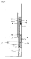
- FIG. 5 is a front view in which the cover plate of the present invention is removed.
- a moving guide 2 is combined to a fixed guide 1 which is fixed to a wall to enable the moving guide 2 to vertically slide along the fixed guide 1.
- a cover plate 3 is fixed and combined to the moving guide 2 so that the moving guide 2 cannot be separated from the fixed guide 1.
- the lower portion of the fixed guide 1 is coupled to the lower portion of the cover plate 3 via springs 4, a driving means 10 having a pulley 6 for winding a wire 5 is installed in the fixed guide 1.
- the wire 5 is connected to the pulley 6 and wound around the pulley 6.
- the end of the wire 5 is connected to the lower portion of the cover plate 3 so that the cover plate 3 can be vertically moved by operation of the driving means 10 and a spring 4.
- An upper lead switch 13 is mounted to the upper portion of the moving guide 2, and a lower lead switch 14 is mounted to the lower portion of the moving guide 2.
- Magnetic bodies 15 and 16 are under the upper and lower portions of the fixed guide 1, respectively. Magnetic bodies 15 and 16 contact the upper and lower lead switches 13 and 14, respectively, when the moving guide 2 is vertically moved. Therefore, the vertical height of the cover plate 3 can be restricted by operation of the lead switches 13 and 14 due to magnetic bodies 15 and 16.
- the driving means 10 comprises the wire 5 on which a gear is formed, the pulley 6 around which the wire 5 is wound, a plurality of gears 10 meshed with each other, and a motor 12.
- One of the gears 10 is geared with the pulley 6, and another of the gears 10 is geared with a shaft of the motor 10. Therefore, when a switching means (not shown in the Drawings) is turned on to operate the motor 12, the wire 5 is wound around the pulley 6 or released from the pulley 6.
- a conventional switch may be used as the switch means of the invention, but it is more effective to use a speech recognition switch that has been recently developed.
- the user turns on the driving means 10 installed in the inner side of the cover plate 3. That is, when the motor 12 of the driving means 10 is operated according to manipulation of the switch means, the gears 11 meshed with the shaft of the motor 12 are rotated, and thus the pulley 6 is rotated.
- a conventional up-down switch may be used as the switch means, it is more effective to use a speech recognition switch that has been recently developed.
- the apparatus of the present invention is installed and used in a place where water is used.
- the speech recognition switch is waterproofed and may be fixed to the inner surface of the cover plate 3 to improve the appearance and the waterproof effect. In this way, trouble of the switch due to water can be prevented.
- the motor 12 of the driving means 10 When a user selects the "up" mode of the switch means to move the cover plate 3 upwardly, the motor 12 of the driving means 10 is operated. The rotational force of the motor 12 is transmitted to and reduced by the gears 11. Then, the reduced rotational force is transmitted to the pulley 6 to rotate it. Thus, the wire 5 is wound around the rotating pulley 6 .
- the cover plate 3 When the wire 5 is wound around the pulley 6, the cover plate 3 is moved upward due to the wire 5, and the moving guide 2 fixed to the cover plate 3 is slid upward along the fixed guide 1. At this time, the resilient force of the springs 4 fixed between the lower portion of the fixed guide 1 and the lower portion of the cover plate 3 assists smooth upward movement of the cover plate 3.
- the user controls the switch means to halt an operation of the motor 12 of the driving means 10, thus the rotation of the gears 11 and the pulley 6 is stopped and the upward movement of the washstand 7 is stopped (see FIG. 3).
- the wire 5 on which the gear is formed is meshed with the pulley 6, the wire 5 wound around pulley 6 cannot be released from the pulley 6 though the pulley 6 is not rotated.
- the washstand 7 Although the washstand 7 reaches the upper limit, the washstand 7 is continuously moved upward if a user does not control the switch means.
- the lead switch 14 is used as a safety device to prevent safety accidents.
- the washstand 7 reaches the upper limit, the lead switch 14 installed at the lower portion of the moving guide 2 comes close to the magnetic body 16 located at the lower portion of the fixed guide 1, and thus the lead switch 14 is operated.
- the power supplied to the driving means 10 is stopped due to operation of the lead switch 14 and the motor 12 is not operated so that the pulley 6 is not rotated and the upward movement of the washstand 7 is halted.
- the user controls the switch means to halt operation of the motor 12 of the driving means 10, and so the rotation of the gears 11 and the pulley 6 is stopped and the downward movement of the washstand 7 is stopped (see FIG. 4).
- the washstand 7 Although the washstand 7 reaches the lower limit, the washstand 7 is continuously moved downward if a user does not control the switch means.
- the present invention uses the lead switch 13 as a safety device to prevent safety accidents.
- the lead switch 13 installed at the upper portion of the moving guide 2 comes close to the magnetic body 15 located at the upper portion of the fixed guide 1, and thus the lead switch 13 is operated.
- the power supplied to the driving means 10 is stopped due to operation of the lead switch 13 and the motor 12 is not operated so that the pulley 6 is not rotated and the downward movement of the washstand 7 is halted.
- the spring 4 connecting the lower portion of the fixed guide 1 to the lower portion of the cover plate 3 performs a complementary role to enable the cover plate 3 to smoothly move downward or upward by the nature of the spring 4.
- the coil pipes 8 are used as the pipes for supplying cold and hot water, the coil pipes 6 are extended or shrunk when the washstand 7 is moved upward or downward so that the upward and downward movement of the washstand 7 is not affected by the coil pipes 8.
- the antenna-type drainpipe 9 is used as a drainpipe, the antenna-type drainpipe 9 is extended when the washstand 7 is moved upward. On the contrary, when the washstand 7 is moved downward, the antenna-type drainpipe 9 is retracted.
- a taller or smaller person can adjust freely the height of the washstand to fit it to his physical feature so that he can conveniently use the washstand without strain on the user's waist. Also, there is no need to use an auxiliary means for a small person or child to fit his stature to the height of the washstand, and thus possible accidents by an auxiliary means may be prevented.
Landscapes
- Engineering & Computer Science (AREA)
- Health & Medical Sciences (AREA)
- Public Health (AREA)
- Environmental & Geological Engineering (AREA)
- Life Sciences & Earth Sciences (AREA)
- Hydrology & Water Resources (AREA)
- Water Supply & Treatment (AREA)
- Sink And Installation For Waste Water (AREA)
- Domestic Plumbing Installations (AREA)
- Body Washing Hand Wipes And Brushes (AREA)
- Combinations Of Kitchen Furniture (AREA)
Claims (3)
- Vorrichtung zum Einstellen der Höhe eines Waschbeckens, mit:einer festen Führung (1), die an einer Wand befestigt werden kann;einer beweglichen Führung (2), welche mit der festen Führung (1) gekoppelt ist, um gleitend in vertikaler Richtung entlang der festen Führung (1) bewegbar zu sein; undeiner Abdeckplatte (3), an welcher ein Waschbecken (7) mit einem Abflussrohr (9) und Rohren (8) zur Zufuhr von kaltem und warmem Wasser angebracht sind und ein Spiegel anbringbar ist, wobei die Abdeckplatte (3) an der beweglichen Führung (2) befestigt ist und die Rohre (8) zur Zufuhr von kaltem und warmem Wasser als Rohrschlangen ausgebildet sind;dadurch gekennzeichnet,
dass die Abdeckplatte (3) durch eine Feder (4) mit der festen Führung (1) verbunden ist, um eine leichtgängige vertikale Bewegung derselben zu unterstützen;
dass das Abflussrohr (9) als Teleskoprohr ausgebildet ist; und
dass an einem oberen Teil der festen Führung (1) ein Antriebsmittel (10) vorgesehen ist, welches einen Motor (12), der mit einem Schaltmittel verbunden ist, eine Seilrolle (6), die mit Getriebestufen (11) im Eingriff steht, die mit einer Welle des Motors (12) gekoppelt sind, und einen Draht (5), der um die Seilrolle (6) wickelbar ist, aufweist, wobei ein Ende des Drahtes (5) an der Seilrolle (6) befestigt ist und das andere Ende mit einem unteren Teil der Abdeckplatte (3) verbunden ist, wodurch der Draht (5) je nach Rotationsrichtung der Seilrolle (6) auf die Seilrolle (6) aufgewickelt oder von der Seilrolle (6) abgewickelt wird, so dass die Abdeckplatte (3) und das Waschbecken (7) durch eine Betätigung des Antriebsmittels (10) nach oben oder nach unten bewegbar sind. - Vorrichtung zum Einstellen der Höhe eines Waschbeckens nach Anspruch 1, ferner aufweisend:Führungsschalter (14), die jeweils an einem oberen und einem unteren Teil der beweglichen Führung (2) vorgesehen sind, wobei die Führungsschalter (14) mit dem Antriebsmittel (10) verbunden sind, um eine exzessive Bewegung der Abdeckplatte (3) einzuschränken; undMagnetkörper (15), die jeweils an einem oberen und einem unteren Teil der Abdeckplatte (3) vorgesehen sind, wodurch die Führungsschalter (14) einen Betrieb des Antriebsmittel (10) steuern, wenn die Abdeckplatte (3) einen oberen Grenzpunkt oder einen unteren Grenzpunkt erreicht, so dass die Abdeckplatte (3) innerhalb des eingeschränkten Bereichs bewegbar ist.
- Vorrichtung zum Einstellen der Höhe eines Waschbeckens nach Anspruch 1, wobei das Schaltmittel als Auf/Ab-Schalter oder als Schallerkennungsschalter ausgebildet ist.
Applications Claiming Priority (3)
| Application Number | Priority Date | Filing Date | Title |
|---|---|---|---|
| KR10-2001-0027198A KR100420140B1 (ko) | 2001-05-18 | 2001-05-18 | 세면대의 높이 조절장치 |
| KR2001027198 | 2001-05-18 | ||
| PCT/KR2002/000844 WO2002094072A1 (en) | 2001-05-18 | 2002-05-07 | Washstand height-adjusting apparatus |
Publications (3)
| Publication Number | Publication Date |
|---|---|
| EP1387633A1 EP1387633A1 (de) | 2004-02-11 |
| EP1387633A4 EP1387633A4 (de) | 2005-01-05 |
| EP1387633B1 true EP1387633B1 (de) | 2007-04-25 |
Family
ID=19709624
Family Applications (1)
| Application Number | Title | Priority Date | Filing Date |
|---|---|---|---|
| EP02771775A Expired - Lifetime EP1387633B1 (de) | 2001-05-18 | 2002-05-07 | Höheneinstellungsvorrichtung für waschbecken |
Country Status (7)
| Country | Link |
|---|---|
| US (1) | US6973684B2 (de) |
| EP (1) | EP1387633B1 (de) |
| KR (1) | KR100420140B1 (de) |
| CN (1) | CN100466954C (de) |
| CA (1) | CA2447298C (de) |
| DE (1) | DE60219780T2 (de) |
| WO (1) | WO2002094072A1 (de) |
Families Citing this family (15)
| Publication number | Priority date | Publication date | Assignee | Title |
|---|---|---|---|---|
| TWI394550B (zh) * | 2009-06-30 | 2013-05-01 | Globe Union Ind Corp | A bathing device for use as a means of bathing and its use |
| DE202010004483U1 (de) * | 2010-04-03 | 2010-06-24 | Schmidt Systemtechnik Gmbh | Waschvorrichtung |
| KR200451753Y1 (ko) * | 2010-05-19 | 2011-01-10 | 한만식 | 어패류 수조용 수면거품제거장치 |
| KR101200790B1 (ko) | 2010-06-28 | 2012-11-13 | 성균관대학교산학협력단 | 하부 개방형 무전원 높이 조절 세면대 |
| KR101253149B1 (ko) | 2010-06-28 | 2013-04-10 | 성균관대학교산학협력단 | 벽면 충돌방지가 가능한 하부 개방형 무전원 높이 조절 세면대 |
| DE202012008864U1 (de) * | 2012-09-17 | 2013-12-18 | Viega Gmbh & Co. Kg | Tragvorrichtung für einen Sanitärkörper |
| DE102013001708A1 (de) * | 2012-09-17 | 2014-03-20 | Viega Gmbh & Co. Kg | Tragvorrichtung für einen Sanitärkörper |
| CN104188578B (zh) * | 2014-09-18 | 2016-09-21 | 新乡学院 | 一种可自动升降洗漱台 |
| CN110868895A (zh) * | 2017-06-22 | 2020-03-06 | Agog 控股私人有限公司 | 可堆叠的厕所 |
| KR101954938B1 (ko) | 2017-09-06 | 2019-03-06 | 주식회사 유디시스템 | 높이 조절형 급수 조절장치 |
| KR102036443B1 (ko) * | 2018-03-26 | 2019-10-24 | 고명묵 | 세면대 승강 장치 |
| US11103062B2 (en) | 2019-05-29 | 2021-08-31 | April Drusilla Calvert | Height-adjustable medicine cart |
| USD925044S1 (en) | 2019-06-24 | 2021-07-13 | April Drusilla Calvert | Adjustable medicine cart |
| KR200490759Y1 (ko) | 2019-07-08 | 2019-12-30 | 신동근 | 휴대용 다용도 기립식 무릎 받침대 |
| CZ308805B6 (cs) * | 2020-06-24 | 2021-05-26 | DOMKAT, s.r.o. | Sestava výškově stavitelné toalety |
Family Cites Families (16)
| Publication number | Priority date | Publication date | Assignee | Title |
|---|---|---|---|---|
| DE2304815A1 (de) * | 1973-02-01 | 1974-08-08 | Hensing Johann | Sanitaer - fertigbauelement |
| GB2162421A (en) * | 1984-08-01 | 1986-02-05 | South African Inventions | Wash-basin |
| KR870001448Y1 (ko) * | 1985-04-23 | 1987-04-15 | 유경준 | 세면대의 높이 조절장치 |
| KR900006396Y1 (ko) * | 1987-07-08 | 1990-07-20 | 유경준 | 세면대의 높이 조절장치 |
| KR900006395Y1 (ko) * | 1987-07-08 | 1990-07-20 | 유경준 | 세면대의 높이 조절장치 |
| US5230109A (en) * | 1992-03-06 | 1993-07-27 | Herman Miller, Inc. | Vertically adjustable lavatory assembly |
| KR0129020B1 (ko) * | 1994-02-04 | 1998-04-10 | 김건한 | 세면대의 높이조절 승강장치 |
| JPH0889427A (ja) | 1994-09-22 | 1996-04-09 | Amakusa Tsurugi Kensetsu Kk | 昇降可能な洗面化粧台 |
| US5628075A (en) * | 1995-02-24 | 1997-05-13 | Dudnik; George | Portable vertically adjustable lavatory assembly |
| GB2307856B (en) * | 1995-12-08 | 2000-04-05 | Eric Perry Hathway | Height-adjustable wash basin |
| JP3203222B2 (ja) | 1998-01-20 | 2001-08-27 | 三洋電機株式会社 | 洗面化粧台 |
| JP2000118967A (ja) * | 1998-10-13 | 2000-04-25 | Tanaka Spring:Kk | 昇降装置 |
| JP2000152887A (ja) | 1998-11-19 | 2000-06-06 | Toyama Kikai Kk | 自立型手動式昇降洗面化粧台 |
| KR200263529Y1 (ko) * | 1999-04-10 | 2002-02-08 | 박성수 | 높낮이 조절 세면대 |
| DE29914404U1 (de) * | 1999-08-17 | 2000-01-13 | Grimm, Karl, 85101 Lenting | Waschbecken verstellbar in Höhe und Tiefe |
| KR200250703Y1 (ko) * | 2001-07-24 | 2001-10-19 | 홍순진 | 높이조절되는 세면대 |
-
2001
- 2001-05-18 KR KR10-2001-0027198A patent/KR100420140B1/ko not_active Expired - Fee Related
-
2002
- 2002-05-07 EP EP02771775A patent/EP1387633B1/de not_active Expired - Lifetime
- 2002-05-07 US US10/478,280 patent/US6973684B2/en not_active Expired - Fee Related
- 2002-05-07 CN CNB028101596A patent/CN100466954C/zh not_active Expired - Fee Related
- 2002-05-07 WO PCT/KR2002/000844 patent/WO2002094072A1/en not_active Ceased
- 2002-05-07 CA CA2447298A patent/CA2447298C/en not_active Expired - Fee Related
- 2002-05-07 DE DE60219780T patent/DE60219780T2/de not_active Expired - Lifetime
Also Published As
| Publication number | Publication date |
|---|---|
| DE60219780D1 (de) | 2007-06-06 |
| CA2447298C (en) | 2010-03-16 |
| WO2002094072A9 (en) | 2004-11-25 |
| US20040168250A1 (en) | 2004-09-02 |
| KR20020088532A (ko) | 2002-11-29 |
| EP1387633A1 (de) | 2004-02-11 |
| KR100420140B1 (ko) | 2004-03-03 |
| US6973684B2 (en) | 2005-12-13 |
| WO2002094072A1 (en) | 2002-11-28 |
| EP1387633A4 (de) | 2005-01-05 |
| CN1722973A (zh) | 2006-01-18 |
| CA2447298A1 (en) | 2002-11-28 |
| DE60219780T2 (de) | 2008-01-17 |
| CN100466954C (zh) | 2009-03-11 |
Similar Documents
| Publication | Publication Date | Title |
|---|---|---|
| EP1387633B1 (de) | Höheneinstellungsvorrichtung für waschbecken | |
| US8719975B2 (en) | Shower system and apparatus | |
| US8776289B2 (en) | Senior friendly shower carrier | |
| CN201515985U (zh) | 一种可升降花洒支架 | |
| KR200243030Y1 (ko) | 세면대의 높이 조절장치 | |
| EP3407850A1 (de) | Unterstützende vorrichtung für behinderte personen | |
| KR100419675B1 (ko) | 이동식 세면대 | |
| KR200263529Y1 (ko) | 높낮이 조절 세면대 | |
| KR200482816Y1 (ko) | 자동 등밀이 장치 | |
| KR20020096352A (ko) | 높낮이 조절이 용이한 세면기 | |
| CN212388683U (zh) | 一种智能下水器 | |
| KR200193000Y1 (ko) | 높낮이 조절이 가능한 세면대 | |
| KR100851292B1 (ko) | 장애인용 높이조절세면대의 편의장치 | |
| CN217419859U (zh) | 一种控制装置 | |
| KR200328676Y1 (ko) | 높이 조절장치 및 상기 높이 조절장치를 구비한 세면대 | |
| KR102414401B1 (ko) | 다기능 수납 구조의 욕조기구 | |
| JP3972602B2 (ja) | シャワー装置 | |
| KR200250149Y1 (ko) | 휴대용 때밀이장치 | |
| CN224016438U (zh) | 一种具有无障碍功能的适老化洗手池 | |
| KR101583735B1 (ko) | 높낮이 조절 세면대 | |
| CN213996465U (zh) | 一种方便调节过滤性能的喷头 | |
| JP2577539Y2 (ja) | 自重補正装置 | |
| JP4099591B2 (ja) | 昇降式ワークトップ | |
| JPH0631590U (ja) | 簡易昇降洗面ユニット | |
| KR101094192B1 (ko) | 핸드 드라이어의 높이 조절장치 |
Legal Events
| Date | Code | Title | Description |
|---|---|---|---|
| PUAI | Public reference made under article 153(3) epc to a published international application that has entered the european phase |
Free format text: ORIGINAL CODE: 0009012 |
|
| 17P | Request for examination filed |
Effective date: 20031121 |
|
| AK | Designated contracting states |
Kind code of ref document: A1 Designated state(s): AT BE CH CY DE DK ES FI FR GB GR IE IT LI LU MC NL PT SE TR |
|
| AX | Request for extension of the european patent |
Extension state: AL LT LV MK RO SI |
|
| A4 | Supplementary search report drawn up and despatched |
Effective date: 20041123 |
|
| RIC1 | Information provided on ipc code assigned before grant |
Ipc: 7E 03C 1/324 A |
|
| RIC1 | Information provided on ipc code assigned before grant |
Ipc: 7A 47K 1/04 A |
|
| GRAP | Despatch of communication of intention to grant a patent |
Free format text: ORIGINAL CODE: EPIDOSNIGR1 |
|
| GRAS | Grant fee paid |
Free format text: ORIGINAL CODE: EPIDOSNIGR3 |
|
| GRAA | (expected) grant |
Free format text: ORIGINAL CODE: 0009210 |
|
| AK | Designated contracting states |
Kind code of ref document: B1 Designated state(s): DE |
|
| REF | Corresponds to: |
Ref document number: 60219780 Country of ref document: DE Date of ref document: 20070606 Kind code of ref document: P |
|
| PLBE | No opposition filed within time limit |
Free format text: ORIGINAL CODE: 0009261 |
|
| STAA | Information on the status of an ep patent application or granted ep patent |
Free format text: STATUS: NO OPPOSITION FILED WITHIN TIME LIMIT |
|
| 26N | No opposition filed |
Effective date: 20080128 |
|
| PGFP | Annual fee paid to national office [announced via postgrant information from national office to epo] |
Ref country code: DE Payment date: 20120530 Year of fee payment: 11 |
|
| PG25 | Lapsed in a contracting state [announced via postgrant information from national office to epo] |
Ref country code: DE Free format text: LAPSE BECAUSE OF NON-PAYMENT OF DUE FEES Effective date: 20131203 |
|
| REG | Reference to a national code |
Ref country code: DE Ref legal event code: R119 Ref document number: 60219780 Country of ref document: DE Effective date: 20131203 |