EP1386564A1 - Federelement für Sitz- und Liegemöbel - Google Patents
Federelement für Sitz- und Liegemöbel Download PDFInfo
- Publication number
- EP1386564A1 EP1386564A1 EP03017157A EP03017157A EP1386564A1 EP 1386564 A1 EP1386564 A1 EP 1386564A1 EP 03017157 A EP03017157 A EP 03017157A EP 03017157 A EP03017157 A EP 03017157A EP 1386564 A1 EP1386564 A1 EP 1386564A1
- Authority
- EP
- European Patent Office
- Prior art keywords
- support
- spring element
- spring
- arms
- plate
- Prior art date
- Legal status (The legal status is an assumption and is not a legal conclusion. Google has not performed a legal analysis and makes no representation as to the accuracy of the status listed.)
- Granted
Links
- 230000000994 depressogenic effect Effects 0.000 claims 1
- 238000002347 injection Methods 0.000 claims 1
- 239000007924 injection Substances 0.000 claims 1
- 210000001331 nose Anatomy 0.000 description 6
- 238000004519 manufacturing process Methods 0.000 description 3
- 238000011161 development Methods 0.000 description 2
- 230000018109 developmental process Effects 0.000 description 2
- 125000006850 spacer group Chemical group 0.000 description 2
- 238000009423 ventilation Methods 0.000 description 2
- 230000007423 decrease Effects 0.000 description 1
- 230000000694 effects Effects 0.000 description 1
- 210000003128 head Anatomy 0.000 description 1
- 238000003780 insertion Methods 0.000 description 1
- 230000037431 insertion Effects 0.000 description 1
- 230000002035 prolonged effect Effects 0.000 description 1
- 239000000725 suspension Substances 0.000 description 1
Images

Classifications
-
- A—HUMAN NECESSITIES
- A47—FURNITURE; DOMESTIC ARTICLES OR APPLIANCES; COFFEE MILLS; SPICE MILLS; SUCTION CLEANERS IN GENERAL
- A47C—CHAIRS; SOFAS; BEDS
- A47C23/00—Spring mattresses with rigid frame or forming part of the bedstead, e.g. box springs; Divan bases; Slatted bed bases
- A47C23/002—Spring mattresses with rigid frame or forming part of the bedstead, e.g. box springs; Divan bases; Slatted bed bases with separate resilient support elements, e.g. elastomeric springs arranged in a two-dimensional matrix pattern
Definitions
- the invention relates to a spring element for sitting or lying surfaces with a base plate fixable on a base on which at least two outwardly facing spring arms are supported, the free Ends cooperate with a support plate, wherein between base plate and support plate an elastic auxiliary body is inserted.
- Spring elements are known for example from DE 93 17 114, in which each spring element is designed as a plastic part is and is provided with a footboard and a top plate, between where an elastic spring body is arranged. Each spring element is in rows with its foot part or a foot plate and columns attached to a support. The head plates form the bearing surface of the cushion element. This cover the spring elements - Apart from the edge and eckêtn spring elements - In its entirety, the sitting or lying area almost completely. When loaded, these spring elements are compressed, when they are relieved, they will be repaired by themselves.
- DE 93 17 114 proposes that a spring element be arranged, inner support body in front; Such support body are changing the spring characteristic exchanged, a graded or a continuous Setting the spring characteristic is not possible.
- this spring element so on to be able to form at least graded its hardness can, where an economic production be guaranteed should.
- the elastic support body inserted into the spring element has a Auflagering on, with this on the base plate of the spring element is supported.
- the support ring on the foot plate of the spring element is freely rotatable.
- the support body can be any angular position occupy against the spring element.
- the opening provided the ring member of the support ring such that the Means for securing the spring element recessed on the base are. This allows the auxiliary body of the support element already preparatory be used in the manufacture of the spring elements.
- the elastic support body at least two support arms.
- the curvature corresponds to the spring arms of the spring element.
- the support plate is for receiving a Telleraufsatzes set, with the support plate of the spring element - For example, by positive means - firmly connected is.
- a plate attachment is advantageous with cantilevered Provided with the support plate in an effect context stands.
- the cantilevered arms and the corresponding, inward facing parts of the support plates noses and Depressions or recesses, which interact with the position the plate attachment against the support plate of the spring element fix.
- an adjusting disk is in the supporting body arranged so that they are in the apex of the U- or V-shaped Engage the design of the support arms.
- Periphery are on the Adjusting disc provided for each of the support arms strips, made up of raise the surface of the support disc with increasing height and in Art of "inclined planes" interact with the corresponding sections, these raise against their normal position and so their spring hardness change.
- this adjusting disc with two each other firmly connected opposite spring arms of the spring element, so that the support body is rotated relative to the adjusting disk.
- the as an inclined plane formed strips then act as an adjusting the spring rate, by the end arms of the support spring more or less lift and so pretend.
- At least these two extreme positions are advantageous thereby adjustable, that support plate and support plate have stops, which limit the two extreme positions.
- the plate attachment is rotated relative to the support plate, wherein the Support insert and the spring element latching cooperating means have, for example in the form of noses and corresponding recesses or recesses. Grasps a nose in such a depression is fixed this position and can only be changed by that this nose from this depression by means of a certain, the parts elastically deforming force is brought out. That's it possible, the degree of hardness of the spring element by rotation of the support body against the spring element between the minimum value and the To change maximum value.
- these lugs are arranged in a ring, wherein the one Plate, the backing plate or the support plate, with at least one Nose, the other has the plate, the support plate or the support plate, a plurality of noses, the at least circular section arranged to cover the adjustment range.
- the support plate to improve the rear ventilation provided with means that lift the unloaded mattress; Such agents are known per se from DE 200 01 616.
- the support plate ring-shaped Recesses in which the mattress lifters are inserted. These are provided with terminal mounting arms, which in turn together with the spring arms of the spring element on the support plate are fixed. This type of insertion of the mattress lifter allows a particularly simple and therefore economical production.
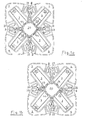
- the example of DE 297 21 655 known spring element 1 has a foot plate 2, with the spring element 1 on a base (not shown in detail) placed and supported.
- This document can be a plate, or - like a slatted frame - one Number of equidistant, parallel slats.
- From the foot plate 2 of the spring element 1 initially run outwardly directed spring arms 3, which are provided with a corrugated spring part 3.1, to the attachment ends 3.2 are formed.
- On these attachment ends 5.2 a support plate 5 is placed, which is approximately parallel to the base plate 2 is aligned and the openings has a rear ventilation allow the laid mattress (not shown).
- the support plate is advantageously divided, it has terminal Surfaces 5.1, which via spacers 5.2 with each other to the support plate 5 are connected.
- the supporting body 10 is arranged, adjusted with the degree of hardness of the spring element can be.
- This support body 10 is via a support ring 11 placed on the foot plate. Through the opening of the support ring 11 are centrally provided in the foot plate fasteners freely accessible. From the support ring 11 support arms 12 extend abroad, these support arms 12 the spring arms 3 at least in the area the outwardly directed arm parts adapted in their curvature are. At about half the height, the support arms 12 are bent towards the center and form end arms 13, wherein the free ends 13.1 in a on the central axis of the spring element 1 lying support plate 14th pass.
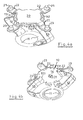
- a plate attachment 20 is provided. To accommodate this plate attachment 20 on the support plate 14, this has a central hole 15th on, in which the central pin 21 of the plate attachment engages; this Central pin is advantageously slotted, so that he with a inserted by the slit possible bias in the support plate 14 can be.
- This plate attachment 20 has further projecting arms 22 which with terminal pins 23 are provided.
- the thus inserted plate attachment 20 is opposite set the support plate, while the support body 10 relative to the Plate attachment 20 is freely rotatable.
- the support body 10 to rotate relative to the spring element 1 adjustable is the support plate 14 with a grip designed adjustment edge 14.1 provided.
- Support plate 14 and plate attachment 20 point to the mutually facing sides cooperating latching means on, for example, in FIG. 4 as setting openings 16 in the Support plate 14 and cooperating with these adjustment pin 25 at de underside of the plate top 20 are shown, without limitation thereon. It goes without saying that such locking means alternatively also between the base plate 2 of the spring element and the support ring 11 can be provided.
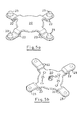
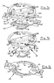
- the support body 30 is arranged, with the spring hardness of the spring element 1 can be adjusted.
- This is in the formed by the spring arms 3 spring body, a support body 30 of the second embodiment used.
- This support body 30 is with its support ring 31 supported on the base plate 2 of the spring element 1. From this support ring go out two support springs 32, the are bent outwards in a V-shape so that they face outward forming facing vertices 32.1.
- the support ring 31 facing part the support spring 32 forms the support arm 33, which faces the support plate 5 Part of the end arm 34, the free ends 34.1 with the support ring 35 are connected and carry this.
- Adjustment knob 37 is provided. With this knob 37 can the Support body 30 are rotated relative to the spring element 1 simply so that the setting can be done from above in a simple manner.
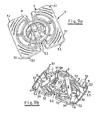
- a control disk 40 is inserted, the one Adjusting ring 41 has.
- the collar 41 are corresponding arranged to two opposing spring arms 3 holder 42, which hold the adjusting disk 40 against rotation in position.
- a spring tongue 43 presses against the support arm 33 and provides for a Stop.
- the adjusting ring 41 is provided with an adjusting bar 44, the from the surface of the collar grows and in the manner of a crooked Level rises to a certain height above this area.
- These Adjusting bar abuts against the inside of the end arm 34 and causes its support, so that with increasing height additional hardness in the spring system is brought and the spring stiffness of the spring element. 1 increases.
- the desired setting remains fixed because the Locking lugs 36 with the teeth 8.1 of the support ring 8 in the sense of a Interlocking connection cooperate.
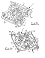
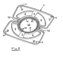
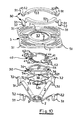
- the support plate 5 For receiving the mattress lifter 50, the support plate 5 has a circular arc Recesses 6 on - in the illustration two each other arranged opposite, take about a semicircle. Around to stabilize the outer ring parts of the support plate 5, These are about holding webs 6 with the trained as a support ring 8 Inner part of the support plate 5 is connected, wherein this holding webs 6 so are guided, that lying in the recesses 6 Lifterschreiben 53 of these retaining webs 7 are under attack. To the Lifterschreiben 53 are formed with a bow-like approach spring arms 51, which in spring arms 51 pass over. The ends of these spring arms 51 are provided with openings 52 provided.
- the spring arms 51 at the in the corner region of the terminal surfaces 5.1 of the support plate 5 arranged fixing pins 9 are set.
Landscapes
- Springs (AREA)
- Chairs For Special Purposes, Such As Reclining Chairs (AREA)
- Invalid Beds And Related Equipment (AREA)
- Mattresses And Other Support Structures For Chairs And Beds (AREA)
Abstract
Description
- Figur 1:
- Federelement erste Ausführungsform mit Stützkörper,
Aufsicht,
- Fig. 1a: Stützarme in Flucht mit Federarmen,
- Fig. 1b: Stützarme auf Lücke mit Federarmen;
- Figur 2:
- Federelement entspr. Fig. 1, Isometrie von oben,
- Fig. 2a: Stützarme in Flucht mit Federarmen,
- Fig. 2b: Stützarme auf Lücke mit Federarmen;
- Figur 3:
- Stützkörper erste Ausführungsform, Isometrie von oben;
- Figur 4:
- Stützkörper erste Ausführungsform mit Telleraufsatz,
- Fig. 4a: Isometrie von oben;
- Fig. 4b: Isometrie von unten;
- Figur 5:
- Telleraufsatz erste Ausführungsform,
- Fig. 5a: Isometrie von oben,
- Fig. 5b: Isometrie von unten.
- Figur 6:
- Federelement zweite Ausführungsform mit Stützkörper,
- Fig. 6a: Isometrie von oben,
- Fig. 6b: Isometrie von unten;
- Figur 7:
- Stützköper zweite Ausführungsform,
- Fig. 7a: Stützeinsatz komplett, isometrische Darstellung
- Fig. 7b: Stützköper, isometrische Darstellung,
- Fig. 7c: Stellteller, isometrische Darstellung,
- Figur 8:
- Auflageteller zweite Ausführungsform, Untersicht;
- Figur 9:
- Federelement zweite Ausführungsform mit Matratzenlifter,
- Fig. 9a: Isometrie von oben,
- Fig. 9b: Isometrie von unten;
- Figur 10:
- Federelement zweite Ausführungsform mit Matratzenlifter, Explosionsdarstellung.
Claims (15)
- Federelement (1) für Sitz- oder Liegeflächen mit einer auf einer Unterlage festlegbaren Fußplatte (2), auf der mindestens zwei nach außen weisende Federarme (3) abgestützt sind, deren freie Enden (3.1) mit einem Auflageteller (5) zusammenwirken, wobei zwischen Fußplatte (2) und Auflageteller (5) ein elastischer Hilfskörper eingesetzt ist, dadurch gekennzeichnet, dass der elastische Hilfskörper als in dem Federelement (1) zur Veränderung dessen Härtegrades verdrehbarer Stützkörper (10) ausgebildet ist, an dessen auf die Innenseite der Fußplatte (2) aufgesetzten Fußteil mit Auflagering (11) höchsten so viele der Krümmung der Federarme (3) des Federelements (1) angepasste Stützarme (12) angesetzt sind, wie Federarme (3) vorhanden sind, die derart angeordnet sind, dass jeder der Stützarme (12) mit einem Federarm (3) in Flucht oder auf Lücke bringbar ist und mit diesem zur Beeinflussung der Härte des Federelements (1) zusammenwirkt.
- Federelement nach Anspruch 1, dadurch gekennzeichnet, dass die Stützarme (12) von dem als Auflagering (11) ausgebildeten Fußteil auswärts abgehend in zur Zentralachse des Federelements (1) hin gerichtete Endarme (13) übergehen, deren freie Enden (13.1) in einem Stützteller (14) enden.
- Federelement nach Anspruch 1 oder 2, dadurch gekennzeichnet, dass der Stützteller (14) eine Zentralöffnung (15) sowie einen aufgesetzten Telleraufsatz (20) aufweist, der mit einem in die Zentralöffnung (15) eingreifenden Zentralzapfen (21) drehbar auf den Stützteller (14) aufgesetzt ist, wobei der Telleraufsatz (20) auskragende Arme (22) aufweist, die mit endständigen Nasen (23) versehen in korrespondierende Öffnungen (8) des Auflagetellers (5), vorzugsweise gebildet von den endständigen Flächen (5) und diese verbindenden Zwischenstücke (6) eingreifen, wobei vorzugsweise die Anzahl der auskragenden Arme (22) der Anzahl der mit endständigen Flächen (3.2) versehenen Federarme (3) des Federelements (1) entspricht.
- Federelement nach einem der Ansprüche 1 bis 3, dadurch gekennzeichnet, dass die freien Enden (13.1) der Endarme (13) der Stützarme (12) des Stützköpers (10) direkt oder indirekt mit dem Auflageteller (5) des Federelements (1) in Wirkverbindung stehen.
- Federelement nach einem der Ansprüche 1 bis 4, dadurch gekennzeichnet, dass der Stützkörper (10) in dem Federelement (1) in Schritten so verdrehbar ist, dass in der einen Extremstellung jeder der Stützarme (12) mit dem korrespondierenden Federarm (3) in Flucht steht, und dass in der anderen Extremstellung jeder der Stützarme (12) zu den Federarmen (3) auf Lücke steht, wobei zumindest die beiden Extremstellungen des Stützkörpers (10) gegenüber dem Federelement (1) einstellbar sind und vorzugsweise mittels Rastmittel einstellbar sind.
- Federelement nach Anspruch 5, dadurch gekennzeichnet, dass die Rastmittel zwischen dem Auflagering (11) des Stützkörpers (10) und der Fußplatte (2) des Federelements (1) oder zwischen dem Stützteller (14) des Stützkörpers (10) und dem Auflageteller des Federelements (1) oder zwischen dem Stützteller (14) des Stützkörpers (10) und dem auf diesen aufgesetzten, mit dem Auflageteller des Federelements (1) verbundenen Telleraufsatz (20) oder zwischen Stützteller (14) und Telleraufsatz (20) eine Anzahl von zum Zentralloch (15) bzw. zum Zentralzapfen (21) konzentrisch angeordnete Einstellöffnungen (16) sowie zumindest einen dazu korrespondierenden Einstellzapfen (25) vorgesehen sind.
- Federelement für Sitz- oder Liegeflächen mit einer auf einer Unterlage festlegbaren Fußplatte, auf der mindestens zwei nach außen weisende Federarme abgestützt sind, deren freie Enden mit einem Auflageteller zusammenwirken, wobei zwischen Fußplatte und Auflageteller ein elastischer Hilfskörper eingesetzt ist, dadurch gekennzeichnet, dass der elastische Hilfskörper als in dem Federelement (1) zur Veränderung dessen Härtegrades verdrehbarer Stützkörper (30) ausgebildet ist, an dessen auf die Innenseite der Fußplatte (2) aufgesetztes Fußteil mit Auflagering (31) zumindest ein Paar Stützfedern (32) angesetzt sind, mit Stützarmen (33), die in einem Scheitel (32.1) in zur Zentralachse des Federelements (1) hin gerichtete Endarme (34) übergehen, deren freie Enden (34.1) in einem Stützring (35) enden, und dass in diese Stützfedern (32) eine Stellscheibe (40) eingesetzt ist, die an den einander gegenüberliegenden Federarmen (3) festgelegt ist, und dass in diese Stützfeder (32) eine Stellscheibe (40) mit Stellring (41) so eingelegt ist, dass dessen Umfang in deren nach außen gerichteten Scheiteln (32.1) der Stützfedern (32) liegt, wobei auf dem Stellring (41) kreisbogenförmig gekrümmte Stellleisten (44) vorgesehen sind, die aus der Oberfläche des Stellringes (41) erwachsend sich bis zu einer maximalen Höhe erheben und Stützarm (33) oder Endarm (34) der Stützfeder (32) abstützend mit diesen zur Beeinflussung der Härte des Federelements (1) zusammenwirken.
- Federelement nach Anspruch 7, dadurch gekennzeichnet, dass der Stellring (41) diametral gegenüber angeordnete paarige Ansätze (42) aufweist, deren freier Abstand der Breite der Federarme (3) entspricht, und dass vorzugsweise zwischen den beiden Ansätzen (42) eines Paares eine Federzunge (43) zum Andrücken an den Federarm (3) angeordnet ist.
- Federelement nach Anspruch 7 oder 8, dadurch gekennzeichnet, dass der Stützkörper (10; 30) einen Knebel (37) zum Verstellen des Stützkörpers (10; 30) aufweist, der nach Zusammenbau in der Zentralöffnung (5.3) des Auflagetellers (5) liegt, wobei vorzugsweise Rastmittel zum Festlegen der Einstellungen des Stützkörpers (10; 30) gegenüber dem Federelement (1) vorgesehen sind.
- Federelement nach Anspruch 9, dadurch gekennzeichnet, dass die Rastmittel zwischen dem Auflagering (11) des Stützkörpers (10) und der Fußplatte (2) des Federelements (1) oder zwischen dem Stützteller (14) des Stützkörpers (10) und dem Auflageteller (5) des Federelements (1) oder zwischen dem Stützteller (14) des Stützkörpers (10) und dem auf diesen aufgesetzten, mit dem Auflageteller des Federelements (1) verbundenen Telleraufsatz (20).
- Federelement nach Anspruch 10, dadurch gekennzeichnet, dass der Stützteller bzw. Auflagering (14; 31) als Rastmittel mindestens eine Gruppe von Nasen (36) aufweist, und dass der Auflageteller (5) mit einer Ringnut (8) versehen ist, in deren Grund eine mit der/den Nase/Nasen (36) zusammenwirkende Zahnung (8.1) vorgesehen ist.
- Federelement nach Anspruch 10 oder 11, dadurch gekennzeichnet, dass als Rastmittel zwischen Stützteller (14) und Telleraufsatz (20) eine Anzahl von zum Zentralloch (15) bzw. zum Zentralzapfen (21) konzentrisch angeordnete Einstellöffnungen (16) sowie zumindest einen dazu korrespondierenden Einstellzapfen (25) vorgesehen sind.
- Federelement nach einem der Ansprüche 1 bis 12, gekennzeichnet durch einen Matratzenlifter (50), der mit seinem Lifterrücken (53) durch Ausnehmungen (6) in dem Auflageteller (5) geführt ist, wobei der Lifterrücken (53) mittels Federarmen so am Auflageteller (5) festgelegt ist, dass der Lifterrücken (53) bei belasteter Matratze niedergedrückt ist, so dass die Matratze auf dem Auflageteller (5) aufliegt, während bei unbelasteter Matratze der Matratzenlifter (50) mit seinem Lifterrücken (53) diese von dem Auflageteller (5) abhebt, wobei vorzugsweise der Lifterrücken (53) und die Ausnehmungen (6) in dem Auflageteller (5) kreisabschnittförmig gebogen sind und der Lifterrücken (53) mit Spiel in diesen Ausnehmungen (6) bewegbar ist, und dass der Lifterrücken (53) an beiden Enden je einen Rückstellfederarm (51) aufweist, der am Auflageteller (5) festgelegt ist.
- Federelement nach Anspruch 13, dadurch gekennzeichnet, dass zum Festlegen der Rückstellfederarme (51) gemeinsam mit den Federarmen (3) in den Eckbereichen der endständigen Flächen (5.1) des Auflagetellers (5) Befestigungsstifte (9) angeordnet sind, die sowohl die Befestigungsenden (3.2) der Federarme (3) wie auch die Befestigungsarme (51) des Matratzenlifters (50) aufnehmen.
- Federelement nach einem der Ansprüche 1 bis 14, dadurch gekennzeichnet, dass der Stützkörper (10; 30) und/oder der Telleraufsatz (20) und die Einstellscheibe (50) und/oder der Matratzenlifter (50) mit dem Lifterrücken (53) und die an dessen beiden Enden angeordneten Rückstellfederarme (51) als Kunststoffteile, vorzugsweise als Kunststoff-Spritzgussteile ausgebildet sind.
Applications Claiming Priority (4)
| Application Number | Priority Date | Filing Date | Title |
|---|---|---|---|
| DE20211765 | 2002-07-31 | ||
| DE20211765U | 2002-07-31 | ||
| DE20300248U DE20300248U1 (de) | 2002-07-31 | 2003-01-07 | Federelement für Betten |
| DE20300248U | 2003-01-07 |
Publications (2)
| Publication Number | Publication Date |
|---|---|
| EP1386564A1 true EP1386564A1 (de) | 2004-02-04 |
| EP1386564B1 EP1386564B1 (de) | 2006-02-01 |
Family
ID=30116789
Family Applications (1)
| Application Number | Title | Priority Date | Filing Date |
|---|---|---|---|
| EP03017157A Expired - Lifetime EP1386564B1 (de) | 2002-07-31 | 2003-07-29 | Federelement für Sitz- und Liegemöbel |
Country Status (7)
| Country | Link |
|---|---|
| US (1) | US6826791B2 (de) |
| EP (1) | EP1386564B1 (de) |
| JP (1) | JP4499381B2 (de) |
| AT (1) | ATE316766T1 (de) |
| DE (2) | DE20300248U1 (de) |
| DK (1) | DK1386564T3 (de) |
| ES (1) | ES2256625T3 (de) |
Cited By (7)
| Publication number | Priority date | Publication date | Assignee | Title |
|---|---|---|---|---|
| WO2008119400A1 (de) * | 2007-04-02 | 2008-10-09 | Froli Kunststoffwerk Heinrich Fromme Ohg | Lagerelement für eine polsterauflage von sitz- und liegeflächen |
| EP2412279A1 (de) * | 2010-07-30 | 2012-02-01 | Siegbert Hartmann | Auflagerelement einer Sitz- oder Liegemöbelunterfederung |
| EP3669705A1 (de) | 2018-12-21 | 2020-06-24 | Tournadre SA Standard Gum | Flexibles element mit regulierbarer steifigkeit für liege- und/oder sitzmöbel |
| EP3669706A1 (de) | 2018-12-21 | 2020-06-24 | Tournadre SA Standard Gum | Flexibles element mit einstellbarer höhe |
| FR3090307A1 (fr) | 2018-12-21 | 2020-06-26 | Tournadre Sa Standard Gum | Elément souple à raideur réglable pour meuble de couchage et/ou d’assise |
| US10722042B2 (en) | 2017-05-12 | 2020-07-28 | Tournadre Sa Standard Gum | Element of adjustable stiffness for beds or seats |
| US10932586B2 (en) | 2017-05-12 | 2021-03-02 | Tournadre Sa Standard Gum | Stiffness adjustment device |
Families Citing this family (28)
| Publication number | Priority date | Publication date | Assignee | Title |
|---|---|---|---|---|
| US7005001B2 (en) * | 2004-02-26 | 2006-02-28 | Dayco Products, Llc | X-spring volume compensation for automotive carbon canister |
| US7237845B2 (en) * | 2005-02-15 | 2007-07-03 | Dodaz, Inc. | Furniture designed for sitting and having inner core support assembly |
| DE102007020608B4 (de) * | 2006-05-01 | 2016-02-11 | Hans Ulrich Schwenk | Federelement für Polster |
| DE202006012077U1 (de) * | 2006-08-04 | 2007-09-27 | Froli Kunststoffwerk Heinrich Fromme Ohg | Lagerelement für eine Polsterauflage von Sitz- und Liegeflächen |
| DE202006012078U1 (de) * | 2006-08-04 | 2007-09-27 | Froli Kunststoffwerk Heinrich Fromme Ohg | Lagerelement für eine Polsterauflage von Sitz- und Liegeflächen |
| US20080209644A1 (en) * | 2008-04-11 | 2008-09-04 | Rainer Wieland | Mattress with a Membrane Spring Array |
| US20110179580A1 (en) * | 2008-04-11 | 2011-07-28 | Rainer Wieland | Interconnectable Grid Section for a Mattress Core |
| US8185988B2 (en) * | 2008-04-11 | 2012-05-29 | Somnium, Inc. | Grid spring mattress |
| DE202008005226U1 (de) | 2008-04-15 | 2009-05-28 | Froli Kunststoffwerk Heinrich Fromme Ohg | Federung für eine Polsterung eines Sitzes, einer Rückenlehne bzw. Rückenschale |
| CN101581614B (zh) * | 2008-05-12 | 2012-06-20 | 鸿富锦精密工业(深圳)有限公司 | 扭力计承载治具以及扭力测试装置 |
| DE202008010210U1 (de) | 2008-07-31 | 2008-10-09 | Claus Groth Gmbh | Federvorrichtung für Liegemöbel |
| DE102008050108A1 (de) | 2008-10-06 | 2010-04-08 | Schwenk, Hans Ulrich, Dipl.-Ing. | Härteverstellbares Federelement |
| DE102010045733A1 (de) | 2010-07-30 | 2012-02-02 | Siegbert Hartmann | Auflagerelement einer Sitz- oder Liegemöbelunterfederung |
| DE202010015380U1 (de) * | 2010-11-11 | 2012-02-17 | Hermann Bock Gmbh | Federelement |
| DE202011050741U1 (de) | 2011-07-15 | 2012-07-16 | Froli Kunststoffwerk Heinrich Fromme Ohg | Auflagevorrichtung für eine Polsterunterlage einer Liege- oder Sitzfläche |
| DE102012107887B3 (de) * | 2012-08-27 | 2013-11-14 | U. Leinss GmbH | Flächenfederelement |
| US9901185B2 (en) * | 2014-01-31 | 2018-02-27 | Dreamwell, Ltd. | Mattress including flat springs |
| DE202014104824U1 (de) * | 2014-10-08 | 2015-10-09 | Froli Kunststoffwerk Heinrich Fromme, Inh. Margret Fromme-Ruthmann E.Kfr. | Anordnung mit mehreren Federelementen für eine Polsterunterlage |
| FR3035579B1 (fr) * | 2015-04-30 | 2017-12-08 | Tournadre Sa Standard Gum | Dispositif monobloc de suspension de matelas |
| US9848709B2 (en) * | 2015-06-04 | 2017-12-26 | Donald J. Molenda | Multi layered modular support system for lounge and other applications |
| CN107455992A (zh) | 2016-06-03 | 2017-12-12 | 冷鹭浩 | 弹性模块 |
| CN109788851B (zh) * | 2016-09-29 | 2022-05-27 | 斯迪尔科斯公司 | 柔顺的座椅结构 |
| EP3403538A1 (de) * | 2017-05-16 | 2018-11-21 | Bekina Indurub | Anpassbares matratzenträgerelement |
| CN110397701A (zh) * | 2019-06-17 | 2019-11-01 | 华为技术有限公司 | 一种隔振装置、隔振系统及交通工具 |
| WO2021055441A1 (en) | 2019-09-18 | 2021-03-25 | Steelcase Inc. | Body support member with lattice structure |
| CN112674536B (zh) * | 2019-10-17 | 2024-08-02 | 厦门新技术集成有限公司 | 用于家具的弹性模块和弹性垫 |
| KR102575967B1 (ko) * | 2021-08-02 | 2023-09-07 | 주식회사 현대리바트 | 스프링 조립체 및 이를 포함하는 쿠션 |
| IT202200002057U1 (it) * | 2022-05-20 | 2023-11-20 | Gelli Plast S R L | Sospensione attiva perfezionata. |
Citations (3)
| Publication number | Priority date | Publication date | Assignee | Title |
|---|---|---|---|---|
| DE29916753U1 (de) * | 1999-09-23 | 2000-11-23 | FROLI Kunststoffwerk Heinrich Fromme oHG, 33758 Schloß Holte-Stukenbrock | Federelement für Sitz- oder Liegeflächen |
| DE20107248U1 (de) * | 2001-04-26 | 2001-07-19 | Hartmann, Siegbert, 32584 Löhne | Unterfederungselement eines Sitz- oder Liegemöbels |
| DE20108407U1 (de) * | 2000-05-18 | 2001-08-02 | Diemer, Gregor, 85456 Wartenberg | Stützelement |
Family Cites Families (10)
| Publication number | Priority date | Publication date | Assignee | Title |
|---|---|---|---|---|
| US3595242A (en) * | 1969-03-26 | 1971-07-27 | American Optical Corp | Atrial and ventricular demand pacer |
| CH681950A5 (de) * | 1989-06-08 | 1993-06-30 | Superba Sa | |
| PT100923B (pt) * | 1992-10-01 | 1997-09-30 | Joao Roberto Dias De Magalhaes | Elementos elasticos e respectivos componentes, fabricados por injeccao em materiais plasticos - nao metalicos - destinados a colchoes, assentos ou outros fins |
| EP0653174B1 (de) | 1993-11-10 | 1998-12-09 | SENNE Lizenz + Produkte GmbH | Polsterelement mit einer Vielzahl von in regelmässigen Mustern angeordneten Federelementen |
| DE29507948U1 (de) * | 1995-03-24 | 1996-06-13 | Froli Kunststoffe Heinrich Fromme, 33758 Schloß Holte-Stukenbrock | Polster-Unterlage |
| US6113082A (en) * | 1997-06-27 | 2000-09-05 | Nishikawa Sangyo Co., Ltd. | Spring |
| DE29712721U1 (de) | 1997-07-18 | 1998-09-10 | Froli Kunststoffe Heinrich Fromme, 33758 Schloß Holte-Stukenbrock | Auflageteller für Polsterauflage von Sitz- oder Liegeflächen |
| JP2000125994A (ja) * | 1998-10-28 | 2000-05-09 | Aisin Seiki Co Ltd | 樹脂性クッションエレメント |
| DE29915339U1 (de) * | 1999-09-01 | 2000-01-05 | Hartmann, Siegbert, 32584 Löhne | Federkörper |
| DE20001616U1 (de) | 2000-01-31 | 2001-03-08 | FROLI Kunststoffwerk Heinrich Fromme oHG, 33758 Schloß Holte-Stukenbrock | Lagerelement für Sitz- oder Liegeflächen |
-
2003
- 2003-01-07 DE DE20300248U patent/DE20300248U1/de not_active Expired - Lifetime
- 2003-07-23 US US10/624,543 patent/US6826791B2/en not_active Expired - Fee Related
- 2003-07-29 DK DK03017157T patent/DK1386564T3/da active
- 2003-07-29 JP JP2003203026A patent/JP4499381B2/ja not_active Expired - Fee Related
- 2003-07-29 DE DE50302316T patent/DE50302316D1/de not_active Expired - Lifetime
- 2003-07-29 AT AT03017157T patent/ATE316766T1/de active
- 2003-07-29 ES ES03017157T patent/ES2256625T3/es not_active Expired - Lifetime
- 2003-07-29 EP EP03017157A patent/EP1386564B1/de not_active Expired - Lifetime
Patent Citations (4)
| Publication number | Priority date | Publication date | Assignee | Title |
|---|---|---|---|---|
| DE29916753U1 (de) * | 1999-09-23 | 2000-11-23 | FROLI Kunststoffwerk Heinrich Fromme oHG, 33758 Schloß Holte-Stukenbrock | Federelement für Sitz- oder Liegeflächen |
| DE20108407U1 (de) * | 2000-05-18 | 2001-08-02 | Diemer, Gregor, 85456 Wartenberg | Stützelement |
| EP1155643A2 (de) * | 2000-05-18 | 2001-11-21 | Florian Dr. Heidinger | Stützvorrichtung |
| DE20107248U1 (de) * | 2001-04-26 | 2001-07-19 | Hartmann, Siegbert, 32584 Löhne | Unterfederungselement eines Sitz- oder Liegemöbels |
Cited By (13)
| Publication number | Priority date | Publication date | Assignee | Title |
|---|---|---|---|---|
| US8256043B2 (en) | 2007-04-02 | 2012-09-04 | Froli Kunststoffwerk Heinrich Fromme Ohg | Support element for a cushion cover for seating and lying areas |
| WO2008119400A1 (de) * | 2007-04-02 | 2008-10-09 | Froli Kunststoffwerk Heinrich Fromme Ohg | Lagerelement für eine polsterauflage von sitz- und liegeflächen |
| EP2412279A1 (de) * | 2010-07-30 | 2012-02-01 | Siegbert Hartmann | Auflagerelement einer Sitz- oder Liegemöbelunterfederung |
| US10722042B2 (en) | 2017-05-12 | 2020-07-28 | Tournadre Sa Standard Gum | Element of adjustable stiffness for beds or seats |
| US10932586B2 (en) | 2017-05-12 | 2021-03-02 | Tournadre Sa Standard Gum | Stiffness adjustment device |
| EP3669705A1 (de) | 2018-12-21 | 2020-06-24 | Tournadre SA Standard Gum | Flexibles element mit regulierbarer steifigkeit für liege- und/oder sitzmöbel |
| FR3090306A1 (fr) | 2018-12-21 | 2020-06-26 | Tournadre Sa Standard Gum | Elément souple à raideur réglable pour meuble de couchage et/ou d’assise |
| FR3090307A1 (fr) | 2018-12-21 | 2020-06-26 | Tournadre Sa Standard Gum | Elément souple à raideur réglable pour meuble de couchage et/ou d’assise |
| FR3090305A1 (fr) | 2018-12-21 | 2020-06-26 | Tournadre Sa Standard Gum | Elément souple à hauteur réglable |
| EP3669706A1 (de) | 2018-12-21 | 2020-06-24 | Tournadre SA Standard Gum | Flexibles element mit einstellbarer höhe |
| US11311112B2 (en) | 2018-12-21 | 2022-04-26 | Tournadre Sa Standard Gum | Supple member with adjustable stiffness for lying and/or sitting furniture |
| US11311113B2 (en) | 2018-12-21 | 2022-04-26 | Tournadre Sa Standard Gum | Height-adjustable supple member |
| US11553803B2 (en) | 2018-12-21 | 2023-01-17 | Tournadre Sa Standard Gum | Flexible member with adjustable stiffness for lying and/or sitting furniture |
Also Published As
| Publication number | Publication date |
|---|---|
| DE50302316D1 (de) | 2006-04-13 |
| US6826791B2 (en) | 2004-12-07 |
| JP4499381B2 (ja) | 2010-07-07 |
| ES2256625T3 (es) | 2006-07-16 |
| ATE316766T1 (de) | 2006-02-15 |
| US20040123384A1 (en) | 2004-07-01 |
| EP1386564B1 (de) | 2006-02-01 |
| JP2004065963A (ja) | 2004-03-04 |
| DK1386564T3 (da) | 2006-05-22 |
| DE20300248U1 (de) | 2003-09-11 |
Similar Documents
| Publication | Publication Date | Title |
|---|---|---|
| EP1386564B1 (de) | Federelement für Sitz- und Liegemöbel | |
| EP2139366B1 (de) | Lagerelement für eine polsterauflage von sitz- und liegeflächen | |
| EP0254808B1 (de) | Höhen- und neigungsverstellbare Kopfstütze mit mittlerem Fenster für Kraftfahrzeugsitze | |
| DE102006031296B4 (de) | Drehversteller | |
| DE19828648C2 (de) | Feder und Federanordnung für eine Matratze | |
| EP2347676B1 (de) | Tragstruktur für ein Rückenteil und/oder einen Sitz einer Sitzeinrichtung und Sitzeinrichtung mit einer derartigen Tragstruktur | |
| EP3909477A1 (de) | Vorhangaufhänger | |
| DE20202050U1 (de) | Stützkörper, insbesondere zur elastischen Abstützung eines Sitz- oder Liegeelements | |
| DE20108407U1 (de) | Stützelement | |
| DE60024207T2 (de) | Drehbaugruppe für einen drehstuhl | |
| EP1211969A1 (de) | Federkörper | |
| EP1900310B1 (de) | Federelement zur elastischen Abstützung eines Sitz-oder Liegeelements | |
| EP3087870A1 (de) | Federbauelement, federelement und unterfederung | |
| WO2008015235A1 (de) | Lagerelement für eine polsterauflage für sitz- und liegeflächen | |
| EP2460441A1 (de) | Federelement | |
| EP2412278A1 (de) | Auflagerelement einer Sitz- oder Liegemöbelunterfederung | |
| DE202004005598U1 (de) | Lagerung für Federleisten von Bettlattenrosten | |
| EP0825823B1 (de) | Lattenrost | |
| EP0361007B1 (de) | Festellbare Möbelrolle | |
| EP1251763A1 (de) | Elastisches tragelement | |
| WO2019185621A1 (de) | Federelement | |
| EP2976972A1 (de) | Auflagerelement einer unterfederung eines sitz- oder liegemöbels | |
| DE69503793T2 (de) | Höhenverstellvorrichtung für fahrzeugsitze | |
| EP2289371B1 (de) | Federelement | |
| WO2010055009A1 (de) | Untermatratze für ein bett |
Legal Events
| Date | Code | Title | Description |
|---|---|---|---|
| PUAI | Public reference made under article 153(3) epc to a published international application that has entered the european phase |
Free format text: ORIGINAL CODE: 0009012 |
|
| AK | Designated contracting states |
Kind code of ref document: A1 Designated state(s): AT BE BG CH CY CZ DE DK EE ES FI FR GB GR HU IE IT LI LU MC NL PT RO SE SI SK TR |
|
| AX | Request for extension of the european patent |
Extension state: AL LT LV MK |
|
| 17P | Request for examination filed |
Effective date: 20040514 |
|
| AKX | Designation fees paid |
Designated state(s): AT BE BG CH CY CZ DE DK EE ES FI FR GB GR HU IE IT LI LU MC NL PT RO SE SI SK TR |
|
| GRAP | Despatch of communication of intention to grant a patent |
Free format text: ORIGINAL CODE: EPIDOSNIGR1 |
|
| GRAS | Grant fee paid |
Free format text: ORIGINAL CODE: EPIDOSNIGR3 |
|
| GRAA | (expected) grant |
Free format text: ORIGINAL CODE: 0009210 |
|
| AK | Designated contracting states |
Kind code of ref document: B1 Designated state(s): AT BE BG CH CY CZ DE DK EE ES FI FR GB GR HU IE IT LI LU MC NL PT RO SE SI SK TR |
|
| PG25 | Lapsed in a contracting state [announced via postgrant information from national office to epo] |
Ref country code: SK Free format text: LAPSE BECAUSE OF FAILURE TO SUBMIT A TRANSLATION OF THE DESCRIPTION OR TO PAY THE FEE WITHIN THE PRESCRIBED TIME-LIMIT Effective date: 20060201 Ref country code: SI Free format text: LAPSE BECAUSE OF FAILURE TO SUBMIT A TRANSLATION OF THE DESCRIPTION OR TO PAY THE FEE WITHIN THE PRESCRIBED TIME-LIMIT Effective date: 20060201 Ref country code: RO Free format text: LAPSE BECAUSE OF FAILURE TO SUBMIT A TRANSLATION OF THE DESCRIPTION OR TO PAY THE FEE WITHIN THE PRESCRIBED TIME-LIMIT Effective date: 20060201 Ref country code: IE Free format text: LAPSE BECAUSE OF FAILURE TO SUBMIT A TRANSLATION OF THE DESCRIPTION OR TO PAY THE FEE WITHIN THE PRESCRIBED TIME-LIMIT Effective date: 20060201 Ref country code: FI Free format text: LAPSE BECAUSE OF FAILURE TO SUBMIT A TRANSLATION OF THE DESCRIPTION OR TO PAY THE FEE WITHIN THE PRESCRIBED TIME-LIMIT Effective date: 20060201 |
|
| REG | Reference to a national code |
Ref country code: GB Ref legal event code: FG4D Free format text: NOT ENGLISH |
|
| REG | Reference to a national code |
Ref country code: CH Ref legal event code: EP |
|
| REG | Reference to a national code |
Ref country code: IE Ref legal event code: FG4D Free format text: LANGUAGE OF EP DOCUMENT: GERMAN |
|
| REG | Reference to a national code |
Ref country code: CH Ref legal event code: NV Representative=s name: BOVARD AG PATENTANWAELTE |
|
| REF | Corresponds to: |
Ref document number: 50302316 Country of ref document: DE Date of ref document: 20060413 Kind code of ref document: P |
|
| PG25 | Lapsed in a contracting state [announced via postgrant information from national office to epo] |
Ref country code: BG Free format text: LAPSE BECAUSE OF FAILURE TO SUBMIT A TRANSLATION OF THE DESCRIPTION OR TO PAY THE FEE WITHIN THE PRESCRIBED TIME-LIMIT Effective date: 20060501 |
|
| REG | Reference to a national code |
Ref country code: DK Ref legal event code: T3 |
|
| REG | Reference to a national code |
Ref country code: SE Ref legal event code: TRGR |
|
| REG | Reference to a national code |
Ref country code: GR Ref legal event code: EP Ref document number: 20060401382 Country of ref document: GR |
|
| PG25 | Lapsed in a contracting state [announced via postgrant information from national office to epo] |
Ref country code: PT Free format text: LAPSE BECAUSE OF FAILURE TO SUBMIT A TRANSLATION OF THE DESCRIPTION OR TO PAY THE FEE WITHIN THE PRESCRIBED TIME-LIMIT Effective date: 20060703 |
|
| GBT | Gb: translation of ep patent filed (gb section 77(6)(a)/1977) |
Effective date: 20060613 |
|
| REG | Reference to a national code |
Ref country code: ES Ref legal event code: FG2A Ref document number: 2256625 Country of ref document: ES Kind code of ref document: T3 |
|
| PG25 | Lapsed in a contracting state [announced via postgrant information from national office to epo] |
Ref country code: MC Free format text: LAPSE BECAUSE OF NON-PAYMENT OF DUE FEES Effective date: 20060731 |
|
| ET | Fr: translation filed | ||
| REG | Reference to a national code |
Ref country code: IE Ref legal event code: FD4D |
|
| PLBE | No opposition filed within time limit |
Free format text: ORIGINAL CODE: 0009261 |
|
| STAA | Information on the status of an ep patent application or granted ep patent |
Free format text: STATUS: NO OPPOSITION FILED WITHIN TIME LIMIT |
|
| 26N | No opposition filed |
Effective date: 20061103 |
|
| PG25 | Lapsed in a contracting state [announced via postgrant information from national office to epo] |
Ref country code: CZ Free format text: LAPSE BECAUSE OF FAILURE TO SUBMIT A TRANSLATION OF THE DESCRIPTION OR TO PAY THE FEE WITHIN THE PRESCRIBED TIME-LIMIT Effective date: 20060201 |
|
| PG25 | Lapsed in a contracting state [announced via postgrant information from national office to epo] |
Ref country code: EE Free format text: LAPSE BECAUSE OF FAILURE TO SUBMIT A TRANSLATION OF THE DESCRIPTION OR TO PAY THE FEE WITHIN THE PRESCRIBED TIME-LIMIT Effective date: 20060201 |
|
| PG25 | Lapsed in a contracting state [announced via postgrant information from national office to epo] |
Ref country code: TR Free format text: LAPSE BECAUSE OF FAILURE TO SUBMIT A TRANSLATION OF THE DESCRIPTION OR TO PAY THE FEE WITHIN THE PRESCRIBED TIME-LIMIT Effective date: 20060201 Ref country code: LU Free format text: LAPSE BECAUSE OF NON-PAYMENT OF DUE FEES Effective date: 20060729 Ref country code: HU Free format text: LAPSE BECAUSE OF FAILURE TO SUBMIT A TRANSLATION OF THE DESCRIPTION OR TO PAY THE FEE WITHIN THE PRESCRIBED TIME-LIMIT Effective date: 20060802 |
|
| PG25 | Lapsed in a contracting state [announced via postgrant information from national office to epo] |
Ref country code: CY Free format text: LAPSE BECAUSE OF FAILURE TO SUBMIT A TRANSLATION OF THE DESCRIPTION OR TO PAY THE FEE WITHIN THE PRESCRIBED TIME-LIMIT Effective date: 20060201 |
|
| REG | Reference to a national code |
Ref country code: CH Ref legal event code: PFA Owner name: FROLI KUNSTSTOFFWERK HEINRICH FROMME OHG Free format text: FROLI KUNSTSTOFFWERK HEINRICH FROMME OHG#LIEMKER STRASSE 27#33758 SCHLOSS HOLTE-STUKENBROCK (DE) -TRANSFER TO- FROLI KUNSTSTOFFWERK HEINRICH FROMME OHG#LIEMKER STRASSE 27#33758 SCHLOSS HOLTE-STUKENBROCK (DE) |
|
| PGFP | Annual fee paid to national office [announced via postgrant information from national office to epo] |
Ref country code: SE Payment date: 20120723 Year of fee payment: 10 |
|
| PGFP | Annual fee paid to national office [announced via postgrant information from national office to epo] |
Ref country code: GR Payment date: 20120725 Year of fee payment: 10 |
|
| REG | Reference to a national code |
Ref country code: DE Ref legal event code: R082 Ref document number: 50302316 Country of ref document: DE Representative=s name: PATENTANWAELTE MELDAU - STRAUSS - FLOETOTTO, DE |
|
| PGFP | Annual fee paid to national office [announced via postgrant information from national office to epo] |
Ref country code: IT Payment date: 20120721 Year of fee payment: 10 |
|
| REG | Reference to a national code |
Ref country code: DE Ref legal event code: R082 Ref document number: 50302316 Country of ref document: DE Representative=s name: PATENTANWAELTE MELDAU - STRAUSS - FLOETOTTO, DE Effective date: 20121204 Ref country code: DE Ref legal event code: R081 Ref document number: 50302316 Country of ref document: DE Owner name: FROLI KUNSTSTOFFWERK HEINRICH FROMME, INH. MAR, DE Free format text: FORMER OWNER: FROLI KUNSTSTOFFWERK HEINRICH FROMME OHG, 33758 SCHLOSS HOLTE-STUKENBROCK, DE Effective date: 20121204 |
|
| REG | Reference to a national code |
Ref country code: SE Ref legal event code: EUG |
|
| REG | Reference to a national code |
Ref country code: GR Ref legal event code: ML Ref document number: 20060401382 Country of ref document: GR Effective date: 20140204 |
|
| PG25 | Lapsed in a contracting state [announced via postgrant information from national office to epo] |
Ref country code: SE Free format text: LAPSE BECAUSE OF NON-PAYMENT OF DUE FEES Effective date: 20130730 |
|
| PG25 | Lapsed in a contracting state [announced via postgrant information from national office to epo] |
Ref country code: GR Free format text: LAPSE BECAUSE OF NON-PAYMENT OF DUE FEES Effective date: 20140204 Ref country code: IT Free format text: LAPSE BECAUSE OF NON-PAYMENT OF DUE FEES Effective date: 20130729 |
|
| PGFP | Annual fee paid to national office [announced via postgrant information from national office to epo] |
Ref country code: GB Payment date: 20140721 Year of fee payment: 12 Ref country code: ES Payment date: 20140721 Year of fee payment: 12 |
|
| PGFP | Annual fee paid to national office [announced via postgrant information from national office to epo] |
Ref country code: BE Payment date: 20140722 Year of fee payment: 12 |
|
| GBPC | Gb: european patent ceased through non-payment of renewal fee |
Effective date: 20150729 |
|
| PG25 | Lapsed in a contracting state [announced via postgrant information from national office to epo] |
Ref country code: GB Free format text: LAPSE BECAUSE OF NON-PAYMENT OF DUE FEES Effective date: 20150729 |
|
| REG | Reference to a national code |
Ref country code: FR Ref legal event code: PLFP Year of fee payment: 14 |
|
| REG | Reference to a national code |
Ref country code: ES Ref legal event code: FD2A Effective date: 20160826 |
|
| PGFP | Annual fee paid to national office [announced via postgrant information from national office to epo] |
Ref country code: DK Payment date: 20160722 Year of fee payment: 14 |
|
| PG25 | Lapsed in a contracting state [announced via postgrant information from national office to epo] |
Ref country code: ES Free format text: LAPSE BECAUSE OF NON-PAYMENT OF DUE FEES Effective date: 20150730 |
|
| REG | Reference to a national code |
Ref country code: FR Ref legal event code: PLFP Year of fee payment: 15 |
|
| PG25 | Lapsed in a contracting state [announced via postgrant information from national office to epo] |
Ref country code: BE Free format text: LAPSE BECAUSE OF NON-PAYMENT OF DUE FEES Effective date: 20150731 |
|
| REG | Reference to a national code |
Ref country code: DK Ref legal event code: EBP Effective date: 20170731 |
|
| REG | Reference to a national code |
Ref country code: FR Ref legal event code: PLFP Year of fee payment: 16 |
|
| PG25 | Lapsed in a contracting state [announced via postgrant information from national office to epo] |
Ref country code: DK Free format text: LAPSE BECAUSE OF NON-PAYMENT OF DUE FEES Effective date: 20170731 |
|
| PGFP | Annual fee paid to national office [announced via postgrant information from national office to epo] |
Ref country code: CH Payment date: 20180725 Year of fee payment: 16 Ref country code: AT Payment date: 20180719 Year of fee payment: 16 |
|
| REG | Reference to a national code |
Ref country code: DE Ref legal event code: R082 Ref document number: 50302316 Country of ref document: DE Representative=s name: BOEHMERT & BOEHMERT ANWALTSPARTNERSCHAFT MBB -, DE Ref country code: DE Ref legal event code: R082 Country of ref document: DE Ref country code: DE Ref legal event code: R082 Ref document number: 50302316 Country of ref document: DE Representative=s name: BAUER WAGNER PRIESMEYER PATENT- UND RECHTSANWA, DE |
|
| REG | Reference to a national code |
Ref country code: CH Ref legal event code: PL |
|
| REG | Reference to a national code |
Ref country code: AT Ref legal event code: MM01 Ref document number: 316766 Country of ref document: AT Kind code of ref document: T Effective date: 20190729 |
|
| PG25 | Lapsed in a contracting state [announced via postgrant information from national office to epo] |
Ref country code: AT Free format text: LAPSE BECAUSE OF NON-PAYMENT OF DUE FEES Effective date: 20190729 |
|
| PG25 | Lapsed in a contracting state [announced via postgrant information from national office to epo] |
Ref country code: CH Free format text: LAPSE BECAUSE OF NON-PAYMENT OF DUE FEES Effective date: 20190731 Ref country code: LI Free format text: LAPSE BECAUSE OF NON-PAYMENT OF DUE FEES Effective date: 20190731 |
|
| REG | Reference to a national code |
Ref country code: DE Ref legal event code: R082 Ref document number: 50302316 Country of ref document: DE Representative=s name: BOEHMERT & BOEHMERT ANWALTSPARTNERSCHAFT MBB -, DE Ref country code: DE Ref legal event code: R082 Ref document number: 50302316 Country of ref document: DE |
|
| REG | Reference to a national code |
Ref country code: DE Ref legal event code: R082 Ref document number: 50302316 Country of ref document: DE Representative=s name: BOEHMERT & BOEHMERT ANWALTSPARTNERSCHAFT MBB -, DE |
|
| PGFP | Annual fee paid to national office [announced via postgrant information from national office to epo] |
Ref country code: NL Payment date: 20220720 Year of fee payment: 20 |
|
| PGFP | Annual fee paid to national office [announced via postgrant information from national office to epo] |
Ref country code: DE Payment date: 20220509 Year of fee payment: 20 |
|
| PGFP | Annual fee paid to national office [announced via postgrant information from national office to epo] |
Ref country code: FR Payment date: 20220725 Year of fee payment: 20 |
|
| REG | Reference to a national code |
Ref country code: DE Ref legal event code: R071 Ref document number: 50302316 Country of ref document: DE |
|
| REG | Reference to a national code |
Ref country code: NL Ref legal event code: MK Effective date: 20230728 |