EP1384895A2 - Entlüftungsvorrichtung einer Tauchmotorpumpe - Google Patents
Entlüftungsvorrichtung einer Tauchmotorpumpe Download PDFInfo
- Publication number
- EP1384895A2 EP1384895A2 EP03014788A EP03014788A EP1384895A2 EP 1384895 A2 EP1384895 A2 EP 1384895A2 EP 03014788 A EP03014788 A EP 03014788A EP 03014788 A EP03014788 A EP 03014788A EP 1384895 A2 EP1384895 A2 EP 1384895A2
- Authority
- EP
- European Patent Office
- Prior art keywords
- pump
- submersible pump
- holder
- liquid
- closure body
- Prior art date
- Legal status (The legal status is an assumption and is not a legal conclusion. Google has not performed a legal analysis and makes no representation as to the accuracy of the status listed.)
- Granted
Links
Images

Classifications
-
- F—MECHANICAL ENGINEERING; LIGHTING; HEATING; WEAPONS; BLASTING
- F04—POSITIVE - DISPLACEMENT MACHINES FOR LIQUIDS; PUMPS FOR LIQUIDS OR ELASTIC FLUIDS
- F04D—NON-POSITIVE-DISPLACEMENT PUMPS
- F04D29/00—Details, component parts, or accessories
- F04D29/60—Mounting; Assembling; Disassembling
- F04D29/605—Mounting; Assembling; Disassembling specially adapted for liquid pumps
- F04D29/606—Mounting in cavities
-
- F—MECHANICAL ENGINEERING; LIGHTING; HEATING; WEAPONS; BLASTING
- F04—POSITIVE - DISPLACEMENT MACHINES FOR LIQUIDS; PUMPS FOR LIQUIDS OR ELASTIC FLUIDS
- F04D—NON-POSITIVE-DISPLACEMENT PUMPS
- F04D9/00—Priming; Preventing vapour lock
- F04D9/001—Preventing vapour lock
Definitions
- the invention relates to a device for maintaining absorbency one arranged in a pump sump, screwless by means of a holder submersible pump attached to a foot elbow.
- the invention has for its object a device of the beginning to create the type mentioned, in which the maintenance of absorbency without an am Housing of the submersible pump to be made and with little effort measure to be retrofitted.
- a preferred embodiment of the invention has one for this purpose conical tapered bore in which a spherical or conical Closure body is arranged.
- the Bracket is equipped with an upward hole and a attached piping that goes into a manifold with a down directional opening passes, the opening through a floating Closure body is to be closed.
- the floating closure body by a movable on the manifold attached flap formed by the rising in the pump sump Liquid is pressed against the opening of the elbow.
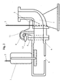
- FIGS. 1 and 2 have the following features together:
- a submersible pump 1 is by means of a chain 2 attached to its top into and out of a pump sump (not shown here) draggable.
- the submersible pump 1 is guided with the aid of two wire cables 3, which are enclosed by a part serving as a holder 4.
- the holder 4 slides on the wire ropes 3 that it encloses.
- the bracket 4 has one or two claws 5, the last part the lowering process, the back of a flange 6 on a pipe bend 7 capture in order to then come to the fixed system on this back.
- This System also has the result that a surface located on the bracket 4 comes to the sealing system at the front of the flange 6.
- the ventilation line 9 is conical running hole formed.
- the vent line 9 is one Floating ball 10 is arranged, which drops as the liquid runs off and thus opens a path through which when the Liquid level the air in the housing of the submersible pump 1 can flow out. If the liquid level continues to rise, it presses the ball 10 on their seat formed in the ventilation line 9. The ventilation line 9 is now closed; leakage of liquid from inside the pump Pump sump is prevented.
- Vent line 9 available. But this turns into an elbow 11, which has a downward opening. In front of this opening there is one by one Hinge or a suspension made of a flexible material pivotable flap 12 arranged. With one falling below their level Liquid level, the flap 12 is moved downward by its own weight, whereby the previously closed opening is released by the flap 12. Thus, here too the vent line 9 is below the level of Closure body falling liquid level opened. The flap 12 is floating up so that they rise above their level Liquid level is closed again.
- the non-return element arranged in the vent line does not have to inevitably be equipped with a floating closure body.
- valves can also be used if there is relief open from the pressure of the liquid in the pump sump and thus a vent line release.
Landscapes
- Engineering & Computer Science (AREA)
- Mechanical Engineering (AREA)
- General Engineering & Computer Science (AREA)
- Structures Of Non-Positive Displacement Pumps (AREA)
Abstract
Description
- Fig. 1
- eine Tauchmotorpumpe mit einer erfindungsgemäß ausgestatteten Halterung, bei der eine Zwangsentlüftung über eine integrierte Bohrung erfolgt;
- Fig. 2
- eine Variante der erfindungsgemäßen Einrichtung, bei der eine Entlüftung über ein auf der Halterung angeordnetes Rohr erfolgt.
Claims (5)
- Einrichtung zur Erhaltung der Saugfähigkeit einer in einem Pumpensumpf angeordneten, mittels einer Halterung (4) schraubenlos an einem Fußkrümmer (7) befestigten Tauchmotorpumpe (1), dadurch gekennzeichnet, daß die Halterung (4) mit einer nach oben führenden Entlüftungsleitung (9) versehen ist, welche mit einem den Zutritt von Flüssigkeit aus dem Pumpensumpf in die Tauchmotorpumpe (1) verhindernden Rückschlagorgan (10, 12) ausgestattet ist.
- Einrichtung nach Anspruch 1, dadurch gekennzeichnet, daß in der Halterung (4) eine nach oben gerichtete Bohrung angeordnet ist, in welcher ein aufschwimmender Verschlußkörper (10) mit einem durch eine Verjüngung der Bohrung gebildeten Sitz dichtend zusammenwirkt.
- Einrichtung nach Anspruch 2, gekennzeichnet durch eine sich nach oben konisch verjüngende Bohrung, in welcher ein kugel- oder kegelförmiger Verschlußkörper (10) angeordnet ist.
- Einrichtung nach Anspruch 1, dadurch gekennzeichnet, daß die Halterung (4) ausgestattet ist mit einer nach oben gerichteten Bohrung und einer daran anschließenden Rohrleitung, die in einen Krümmer (11) mit einer nach unten gerichteten Öffnung übergeht, wobei die Öffnung durch einen aufschwimmenden Verschlußkörper (12) zu verschließen ist.
- Einrichtung nach Anspruch 4, dadurch gekennzeichnet, daß der aufschwimmende Verschlußkörper gebildet wird durch eine beweglich an dem Krümmer (11) befestigte Klappe (12), welche durch die im Pumpensumpf ansteigende Flüssigkeit gegen die Öffnung des Krümmers (11) gedrückt wird.
Applications Claiming Priority (2)
| Application Number | Priority Date | Filing Date | Title |
|---|---|---|---|
| DE10233281 | 2002-07-23 | ||
| DE10233281A DE10233281A1 (de) | 2002-07-23 | 2002-07-23 | Einrichtung zur Erhaltung der Saugfähigkeit einer Tauchmotorpumpe |
Publications (3)
| Publication Number | Publication Date |
|---|---|
| EP1384895A2 true EP1384895A2 (de) | 2004-01-28 |
| EP1384895A3 EP1384895A3 (de) | 2005-11-30 |
| EP1384895B1 EP1384895B1 (de) | 2011-05-04 |
Family
ID=29796507
Family Applications (1)
| Application Number | Title | Priority Date | Filing Date |
|---|---|---|---|
| EP03014788A Expired - Lifetime EP1384895B1 (de) | 2002-07-23 | 2003-06-28 | Entlüftungsvorrichtung einer Tauchmotorpumpe |
Country Status (2)
| Country | Link |
|---|---|
| EP (1) | EP1384895B1 (de) |
| DE (2) | DE10233281A1 (de) |
Cited By (1)
| Publication number | Priority date | Publication date | Assignee | Title |
|---|---|---|---|---|
| WO2013135681A1 (de) * | 2012-03-13 | 2013-09-19 | Prominent Dosiertechnik Gmbh | Verdrängerpumpe mit zwangsentlüftung |
Family Cites Families (9)
| Publication number | Priority date | Publication date | Assignee | Title |
|---|---|---|---|---|
| DE1930676U (de) * | 1963-12-20 | 1966-01-05 | Klein Schanzlin & Bekker Ag | Vorrichtung zur selbsttaetigen entleerung der druckleitung einer kreiselpumpe. |
| FR2361558A1 (fr) * | 1976-08-13 | 1978-03-10 | Saint Gobain Techn Nouvelles | Perfectionnements aux pompes centrifuges auto-amorcantes |
| DE8124528U1 (de) * | 1981-08-21 | 1982-03-18 | Franz Eisele & Söhne GmbH & Co KG, 7481 Sigmaringen | Kreiseltauchpumpe |
| SE442324B (sv) * | 1984-05-08 | 1985-12-16 | Flygt Ab | Anordning for att hindra aterstromning av vetska fran en tryckledning genom en pump |
| DE4434461A1 (de) * | 1994-09-27 | 1996-03-28 | Klein Schanzlin & Becker Ag | Tauchmotorpumpe für grob verunreinigte Flüssigkeiten |
| DE19610697A1 (de) * | 1996-03-19 | 1997-09-25 | Abs Pumps Ltd | Fußstück |
| DE19618452B4 (de) * | 1996-05-08 | 2005-05-12 | Robert Bosch Gmbh | Aggregat zum Fördern von Kraftstoff aus einem Vorratstank zu einer Brennkraftmaschine |
| DE29710766U1 (de) * | 1997-06-20 | 1997-08-21 | KVM-Wasser- und Abwassersysteme GmbH, 32602 Vlotho | Auf dem Boden eines Pumpenschachtes festsetzbarer Fuß |
| DE19901032A1 (de) * | 1999-01-14 | 2000-07-20 | Pierburg Ag | Elektrische Brennstoffpumpe |
-
2002
- 2002-07-23 DE DE10233281A patent/DE10233281A1/de not_active Ceased
-
2003
- 2003-06-28 EP EP03014788A patent/EP1384895B1/de not_active Expired - Lifetime
- 2003-06-28 DE DE50313660T patent/DE50313660D1/de not_active Expired - Lifetime
Cited By (2)
| Publication number | Priority date | Publication date | Assignee | Title |
|---|---|---|---|---|
| WO2013135681A1 (de) * | 2012-03-13 | 2013-09-19 | Prominent Dosiertechnik Gmbh | Verdrängerpumpe mit zwangsentlüftung |
| US10677243B2 (en) | 2012-03-13 | 2020-06-09 | Prominent Gmbh | Displacement pump with forced venting |
Also Published As
| Publication number | Publication date |
|---|---|
| EP1384895B1 (de) | 2011-05-04 |
| DE50313660D1 (de) | 2011-06-16 |
| DE10233281A1 (de) | 2004-02-05 |
| EP1384895A3 (de) | 2005-11-30 |
Similar Documents
| Publication | Publication Date | Title |
|---|---|---|
| DE112007002409T5 (de) | Sperrventil für Vakuumabwasserrohr und Vakuumabwassersystem | |
| EP3722525A1 (de) | Heizbarer spülkasten für intelligente toilette | |
| DE102014113638B4 (de) | Vorrichtung zur Entlüftung und Integritätstestung | |
| EP0968370B1 (de) | Dosierpumpe zum dosierten fördern von flüssigkeiten | |
| DE1703187B2 (de) | Ventileinrichtung zur Wiederherstellung der Saugfähigkeit einer Pumpenanlage | |
| EP1384895B1 (de) | Entlüftungsvorrichtung einer Tauchmotorpumpe | |
| EP2871294A1 (de) | Einlaufgarnitur für einen Spülkasten | |
| EP2738032A1 (de) | Tanksystem für ein Kraftfahrzeug | |
| EP3839260A1 (de) | Kreiselpumpe mit einem selbsttätigen ventil | |
| EP3020878B1 (de) | Hydrant mit kontrollrohr | |
| DE2103643C3 (de) | Waschanlage für Scheiben von Kraftfahrzeugen, insbesondere Lichtaustrittsscheiben von Fahrzeugleuchten | |
| EP1716876B1 (de) | Be- und entlüftetes Darmspülgerät | |
| DE673809C (de) | Brennstoff-Foerderanlage fuer Einspritzbrennkraftmaschinen | |
| DE3228443A1 (de) | Nachruestgeraet zur erreichung einer 2 stufenspuelung an wc-spuelkaesten mit aufschwimmerventil am spuelkastenauslauf | |
| DE2337853C2 (de) | Rückstau- und Geruchsverschluß für Flüssigkelten, Insbesondere Abwässer | |
| DE102010026513A1 (de) | Vorrichtung und Verfahren zur Reinigung und/oder Belüftung eines Flüssigkeitsbehälters | |
| DE102005041813B4 (de) | Vorrichtung zum Verringern der Fließgeschwindigkeit einer Hydraulikflüssigkeit für ein hydraulisches System | |
| DE102009009986A1 (de) | Grauwassernutzungsanlagen mit Druckluftheber | |
| DE318086C (de) | ||
| DE2302343A1 (de) | Brennstoff-abflussystem | |
| DE2706542C2 (de) | Entlüftungseinrichtung für eine Anlage zum Speisen einer Düse mit Öl | |
| WO2013087692A1 (de) | Kraftstoff-fördereinheit | |
| EP2120021A1 (de) | Dosiergerät zur Dosierung einer Lösung in eine Flüssigkeit | |
| DE19811473B4 (de) | Entlüftungsanordnung für eine Zentrifugalpumpe | |
| WO2006133929A1 (de) | Handbetriebene kolbensaugpumpe |
Legal Events
| Date | Code | Title | Description |
|---|---|---|---|
| PUAI | Public reference made under article 153(3) epc to a published international application that has entered the european phase |
Free format text: ORIGINAL CODE: 0009012 |
|
| AK | Designated contracting states |
Kind code of ref document: A2 Designated state(s): AT BE BG CH CY CZ DE DK EE ES FI FR GB GR HU IE IT LI LU MC NL PT RO SE SI SK TR |
|
| AX | Request for extension of the european patent |
Extension state: AL LT LV MK |
|
| PUAL | Search report despatched |
Free format text: ORIGINAL CODE: 0009013 |
|
| AK | Designated contracting states |
Kind code of ref document: A3 Designated state(s): AT BE BG CH CY CZ DE DK EE ES FI FR GB GR HU IE IT LI LU MC NL PT RO SE SI SK TR |
|
| AX | Request for extension of the european patent |
Extension state: AL LT LV MK |
|
| 17P | Request for examination filed |
Effective date: 20060107 |
|
| AKX | Designation fees paid |
Designated state(s): DE FR IE SE |
|
| GRAP | Despatch of communication of intention to grant a patent |
Free format text: ORIGINAL CODE: EPIDOSNIGR1 |
|
| GRAS | Grant fee paid |
Free format text: ORIGINAL CODE: EPIDOSNIGR3 |
|
| GRAA | (expected) grant |
Free format text: ORIGINAL CODE: 0009210 |
|
| AK | Designated contracting states |
Kind code of ref document: B1 Designated state(s): DE FR IE SE |
|
| REG | Reference to a national code |
Ref country code: IE Ref legal event code: FG4D Free format text: LANGUAGE OF EP DOCUMENT: GERMAN |
|
| REF | Corresponds to: |
Ref document number: 50313660 Country of ref document: DE Date of ref document: 20110616 Kind code of ref document: P |
|
| REG | Reference to a national code |
Ref country code: DE Ref legal event code: R096 Ref document number: 50313660 Country of ref document: DE Effective date: 20110616 |
|
| REG | Reference to a national code |
Ref country code: SE Ref legal event code: TRGR |
|
| PLBE | No opposition filed within time limit |
Free format text: ORIGINAL CODE: 0009261 |
|
| STAA | Information on the status of an ep patent application or granted ep patent |
Free format text: STATUS: NO OPPOSITION FILED WITHIN TIME LIMIT |
|
| 26N | No opposition filed |
Effective date: 20120207 |
|
| REG | Reference to a national code |
Ref country code: DE Ref legal event code: R097 Ref document number: 50313660 Country of ref document: DE Effective date: 20120207 |
|
| PGFP | Annual fee paid to national office [announced via postgrant information from national office to epo] |
Ref country code: DE Payment date: 20120606 Year of fee payment: 10 Ref country code: IE Payment date: 20120623 Year of fee payment: 10 |
|
| PGFP | Annual fee paid to national office [announced via postgrant information from national office to epo] |
Ref country code: FR Payment date: 20120704 Year of fee payment: 10 Ref country code: SE Payment date: 20120627 Year of fee payment: 10 |
|
| PG25 | Lapsed in a contracting state [announced via postgrant information from national office to epo] |
Ref country code: SE Free format text: LAPSE BECAUSE OF NON-PAYMENT OF DUE FEES Effective date: 20130629 |
|
| REG | Reference to a national code |
Ref country code: SE Ref legal event code: EUG |
|
| REG | Reference to a national code |
Ref country code: IE Ref legal event code: MM4A |
|
| REG | Reference to a national code |
Ref country code: FR Ref legal event code: ST Effective date: 20140228 |
|
| REG | Reference to a national code |
Ref country code: DE Ref legal event code: R119 Ref document number: 50313660 Country of ref document: DE Effective date: 20140101 |
|
| PG25 | Lapsed in a contracting state [announced via postgrant information from national office to epo] |
Ref country code: IE Free format text: LAPSE BECAUSE OF NON-PAYMENT OF DUE FEES Effective date: 20130628 Ref country code: DE Free format text: LAPSE BECAUSE OF NON-PAYMENT OF DUE FEES Effective date: 20140101 |
|
| PG25 | Lapsed in a contracting state [announced via postgrant information from national office to epo] |
Ref country code: FR Free format text: LAPSE BECAUSE OF NON-PAYMENT OF DUE FEES Effective date: 20130701 |