EP1383343B1 - Autostereoskopische Bildanzeigevorrichtung - Google Patents
Autostereoskopische Bildanzeigevorrichtung Download PDFInfo
- Publication number
- EP1383343B1 EP1383343B1 EP03102051.4A EP03102051A EP1383343B1 EP 1383343 B1 EP1383343 B1 EP 1383343B1 EP 03102051 A EP03102051 A EP 03102051A EP 1383343 B1 EP1383343 B1 EP 1383343B1
- Authority
- EP
- European Patent Office
- Prior art keywords
- display
- region
- pixels
- modulator
- backlight
- Prior art date
- Legal status (The legal status is an assumption and is not a legal conclusion. Google has not performed a legal analysis and makes no representation as to the accuracy of the status listed.)
- Expired - Lifetime
Links
- 230000004888 barrier function Effects 0.000 claims description 18
- 230000000007 visual effect Effects 0.000 claims description 17
- 238000012937 correction Methods 0.000 claims description 14
- 239000004973 liquid crystal related substance Substances 0.000 claims description 11
- 230000005540 biological transmission Effects 0.000 claims description 6
- 230000001419 dependent effect Effects 0.000 claims description 3
- 238000010586 diagram Methods 0.000 description 6
- 238000005286 illumination Methods 0.000 description 6
- 230000000694 effects Effects 0.000 description 4
- 238000000034 method Methods 0.000 description 4
- 239000003086 colorant Substances 0.000 description 3
- 230000003993 interaction Effects 0.000 description 3
- 238000003491 array Methods 0.000 description 1
- 238000013461 design Methods 0.000 description 1
- 238000011161 development Methods 0.000 description 1
- 238000001914 filtration Methods 0.000 description 1
- 210000003918 fraction a Anatomy 0.000 description 1
- 239000000203 mixture Substances 0.000 description 1
- 238000012545 processing Methods 0.000 description 1
Images



Classifications
-
- G—PHYSICS
- G02—OPTICS
- G02F—OPTICAL DEVICES OR ARRANGEMENTS FOR THE CONTROL OF LIGHT BY MODIFICATION OF THE OPTICAL PROPERTIES OF THE MEDIA OF THE ELEMENTS INVOLVED THEREIN; NON-LINEAR OPTICS; FREQUENCY-CHANGING OF LIGHT; OPTICAL LOGIC ELEMENTS; OPTICAL ANALOGUE/DIGITAL CONVERTERS
- G02F1/00—Devices or arrangements for the control of the intensity, colour, phase, polarisation or direction of light arriving from an independent light source, e.g. switching, gating or modulating; Non-linear optics
- G02F1/01—Devices or arrangements for the control of the intensity, colour, phase, polarisation or direction of light arriving from an independent light source, e.g. switching, gating or modulating; Non-linear optics for the control of the intensity, phase, polarisation or colour
- G02F1/13—Devices or arrangements for the control of the intensity, colour, phase, polarisation or direction of light arriving from an independent light source, e.g. switching, gating or modulating; Non-linear optics for the control of the intensity, phase, polarisation or colour based on liquid crystals, e.g. single liquid crystal display cells
- G02F1/133—Constructional arrangements; Operation of liquid crystal cells; Circuit arrangements
- G02F1/1333—Constructional arrangements; Manufacturing methods
- G02F1/1335—Structural association of cells with optical devices, e.g. polarisers or reflectors
-
- H—ELECTRICITY
- H04—ELECTRIC COMMUNICATION TECHNIQUE
- H04N—PICTORIAL COMMUNICATION, e.g. TELEVISION
- H04N13/00—Stereoscopic video systems; Multi-view video systems; Details thereof
- H04N13/30—Image reproducers
- H04N13/356—Image reproducers having separate monoscopic and stereoscopic modes
- H04N13/359—Switching between monoscopic and stereoscopic modes
-
- H—ELECTRICITY
- H04—ELECTRIC COMMUNICATION TECHNIQUE
- H04N—PICTORIAL COMMUNICATION, e.g. TELEVISION
- H04N13/00—Stereoscopic video systems; Multi-view video systems; Details thereof
- H04N13/30—Image reproducers
- H04N13/302—Image reproducers for viewing without the aid of special glasses, i.e. using autostereoscopic displays
- H04N13/31—Image reproducers for viewing without the aid of special glasses, i.e. using autostereoscopic displays using parallax barriers
-
- H—ELECTRICITY
- H04—ELECTRIC COMMUNICATION TECHNIQUE
- H04N—PICTORIAL COMMUNICATION, e.g. TELEVISION
- H04N13/00—Stereoscopic video systems; Multi-view video systems; Details thereof
- H04N13/30—Image reproducers
- H04N13/302—Image reproducers for viewing without the aid of special glasses, i.e. using autostereoscopic displays
- H04N13/31—Image reproducers for viewing without the aid of special glasses, i.e. using autostereoscopic displays using parallax barriers
- H04N13/312—Image reproducers for viewing without the aid of special glasses, i.e. using autostereoscopic displays using parallax barriers the parallax barriers being placed behind the display panel, e.g. between backlight and spatial light modulator [SLM]
-
- H—ELECTRICITY
- H04—ELECTRIC COMMUNICATION TECHNIQUE
- H04N—PICTORIAL COMMUNICATION, e.g. TELEVISION
- H04N13/00—Stereoscopic video systems; Multi-view video systems; Details thereof
- H04N13/30—Image reproducers
- H04N13/324—Colour aspects
-
- G—PHYSICS
- G09—EDUCATION; CRYPTOGRAPHY; DISPLAY; ADVERTISING; SEALS
- G09G—ARRANGEMENTS OR CIRCUITS FOR CONTROL OF INDICATING DEVICES USING STATIC MEANS TO PRESENT VARIABLE INFORMATION
- G09G3/00—Control arrangements or circuits, of interest only in connection with visual indicators other than cathode-ray tubes
- G09G3/001—Control arrangements or circuits, of interest only in connection with visual indicators other than cathode-ray tubes using specific devices not provided for in groups G09G3/02 - G09G3/36, e.g. using an intermediate record carrier such as a film slide; Projection systems; Display of non-alphanumerical information, solely or in combination with alphanumerical information, e.g. digital display on projected diapositive as background
- G09G3/003—Control arrangements or circuits, of interest only in connection with visual indicators other than cathode-ray tubes using specific devices not provided for in groups G09G3/02 - G09G3/36, e.g. using an intermediate record carrier such as a film slide; Projection systems; Display of non-alphanumerical information, solely or in combination with alphanumerical information, e.g. digital display on projected diapositive as background to produce spatial visual effects
Definitions
- the present invention relates to an autostereoscopic display.
- Autostereoscopic displays are well-known and examples of such displays are disclosed in EP 0 602 934 , EP 0 656 555 , EP 0 708 351 , EP 0 726 482 , EP 0 829 743 , EP 0 833 183 (equivalent to GB 2 317 710 ) and EP 0 860 728 .
- EP 0 829 744 discloses an example of such a display which is switchable between an autostereoscopic mode and a two dimensional mode.
- An autostereoscopic display capable of providing crosstalk correction for removing or reducing the effects of crosstalk between left eye and right eye images is disclosed in EP 0 953 962 .
- Such displays may, for example, be based on liquid crystal spatial light modulators comprising arrays of picture elements (pixels) which modulate a light source in accordance with image data representing at least two homologous images.
- EP 0 833 183 and GB 2 317 710 discloses a parallax barrier embodied by a liquid crystal device for switching between a barrier mode and a clear mode.
- the barrier is associated with a spatial light modulator of transmissive type to form an autostereoscopic display which can be switched to a two dimensional full resolution mode.
- Transflective displays which are capable of operating selectively in a transmissive mode or a reflective mode are also known.
- An example of a transflective liquid crystal display is disclosed in M. Kubo et al, "Development of advanced TFT with good legibility under any intensity of ambient light", Proceedings of Information Displays Workshop 1999, Sendai, Japan, pages 183 to 186 .
- FIG. 1 of the accompanying drawings illustrates a known type of display which is of the transmissive type and which may be operated in two dimensional (2D) and three dimensional (3D) modes.
- the display comprises a liquid crystal spatial light modulator (SLM) 1 providing an array of pixels such as 2. Colour filtering (not shown) is provided so that the pixels are arranged as groups of red, green and blue (RGB) pixels for displaying a full colour image.
- the pixels are also arranged as columns for displaying interleaved vertical strips of left (L) and right (R) images.
- a backlight 3 is disposed behind the SLM 1 and directs light towards the SLM through a 2D/3D switching arrangement 4, a patterned retarder 5, and an input polariser 6 of the liquid crystal device (LCD) forming the SLM 1.
- Light transmitted through the SLM 1 passes through an output polariser 7.
- the switching arrangement 4 is configured as a polariser which supplies linearly polarised light to the patterned retarder 5.
- the retarder 5 comprises alternating region in the form of a first group of regions such as 8 which have no effect on the polarisation of the light passing therethrough and relatively narrow regions 9 which rotate the polarisation of the light passing therethrough by 90°.
- the polariser 6 is arranged to block light passing through the regions 8 and to transmit light passing through the regions 9 so that the combination of the retarder 5 and the polariser 6 forms a rear parallax barrier with slits corresponding to the regions 9.
- the parallax barrier controls the direction of light passing through the pixels such that light passing through those pixels which display the left eye image forms a left eye viewing window at a predetermined viewing distance from the display whereas light passing through those pixels displaying a right eye image forms a right eye viewing window at the viewing distance.
- the switching arrangement 4 is arranged not to polarise the light from the backlight 3.
- the structure of the patterned retarder 5 is required to be invisible and light from the backlight 3 passes through the pixels in all directions to provide a wide viewing angle.
- the SLM 1 is controlled to display a 2D image.
- FIG. 2 of the accompanying drawings illustrates a typical example of a transflective display which may be used in an autostereoscopic display of the type shown in Figure 1 .
- the display is based on a liquid crystal device having a liquid crystal layer 10 and red, green, and blue colour filters 11.
- a microreflective structure 12 is provided for the reflective mode of operation whereas a backlight 13 is provided for the transmissive mode of operation.
- Polarisers/retarders are provided as shown at 14 and 15.
- the display When a transflective display, for example of the type shown in Figure 2 , is used in a rear parallax barrier autostereoscopic display, for example of the type shown in Figure 1 , the display may be used in the autostereoscopic mode only in the transmissive mode of the SLM.
- the left and right eye viewing windows are produced only by light transmitted from the backlight through the parallax barrier structure.
- ambient light is reflected to the eyes of an observer from the display so that an observer sees a mixture of light transmitted from the backlight through the SLM and ambient light modulated by the SLM and reflected, for example, by the microreflective structure 12 shown in Figure 2 .
- transmitted light modulated by the left and right eye images is seen substantially only by the left and right eyes, respectively, of the observer
- reflected light is seen by both eyes of the observer and this may contribute greatly to image crosstalk which degrades the 3D effect.
- the reflected brightness is 10% of the transmitted brightness, this adds approximately 10% of crosstalk.
- the brightness of the reflected ambient light should be small compared with the transmitted light.
- the resulting image crosstalk greatly degrades the 3D effect to the point where 3D operation is ineffective. This may result in visual stress to the observer.
- an autostereoscopic display comprising a pixellated transflective spatial light modulator, a backlight and a parallax element disposed between the modulator and the backlight, characterised by comprising: an arrangement for substantially preventing transmission of light from the backlight through at least one first region of the modulator to an autostereoscopic viewing region of the display while permitting reflection of ambient light by the modulator; and a controller for setting at least some of the pixels of the at least one first region to a first predetermined transmissivity and for simultaneously setting at least some of the pixels of at least one second region of the modulator to a second predetermined transmissivity less than the first transmissivity so as to display an image providing to a user an indication of the level of ambient reflected light, the indication being based on a visual comparison between the brightness of the at least one first region and the brightness of the at least one second region.
- the arrangement may comprise a screen for substantially preventing the transmission of light from the backlight through the at least one first region.
- the arrangement may comprise a first portion of the backlight disposed behind the at least one first region and switchable off independently of a second portion of the backlight disposed behind the at least one second region.
- an autostereoscopic display comprising a pixellated transflective spatial light modulator, a backlight, and a parallax element disposed between the modulator and the backlight; characterised by comprising a controller for alternately selecting first and second phases of operation, to provide with a visual indication of the level of ambient reflected light, wherein, during the first phase, the controller sets at least some of the pixels of at least one first region of the modulator to a first transmissivity and sets the backlight to supply light of a first intensity through at least some of the at least some pixels of the at least one first region, and wherein, during the second phase, the controller sets at least some of the pixels of at least one second region of the modulator to a second transmissivity less than the first transmissivity and sets the backlight to supply light of a second intensity greater than the first intensity through at least some of the at least some pixels of the at least one second region, the indication being based on a visual comparison between the brightness of the at least one
- the at least one first region may at least partially overlap the at least one second region.
- Each of the at least one first region and the at least one second region may comprise the whole display area of the modulator.
- the controller may be arranged to switch automatically between the first and second phases.
- the display may comprise a first manually operable control for switching between the first and second phases.
- the parallax element may comprise a parallax barrier.
- the screen may comprise part of the parallax element.
- the first transmissivity may be equal to the maximum transmissivity of the pixels.
- the at least one second region may comprise a plurality of second regions.
- the controller may be arranged to set the pixels of the different second regions to different second transmissivities.
- the controller may be arranged to set the pixels of the at least one second region to any one of a plurality of second transmissivities.
- each second transmissivity may form a pattern providing a visual representation of a crosstalk value corresponding to the second transmissivity.
- the display may comprise a second manually operable control for selecting any one of the second transmissivities.
- the controller may be arranged to provide a or the crosstalk value corresponding to the selected second transmissivity.
- the controller may be arranged to perform crosstalk correction of autostereoscopic image data for the modulator in accordance with the crosstalk value.
- the display may have a two dimensional operational mode.
- the controller may be arranged to switch to the two dimensional mode when the crosstalk value exceeds a predetermined threshold.
- the at least some pixels of the first and second regions may be of the same colour.
- the modulator may comprise a liquid crystal device.
- the display may be switched out of the autostereoscopic mode, for example to a 2D mode where crosstalk is irrelevant. It is unnecessary to assess ambient reflected light and crosstalk in such a 2D mode so the display need not give any indication during the 2D mode.
- FIG. 3 shows an autostereoscopic display 20 connected to a computer 21 for supplying 2D and 3D image data to be displayed by the display 20.
- the display 20 comprises a liquid crystal device 22 of the transflective rear parallax barrier type.
- the LCD 22 is connected to a controller 23 which has a manually operable control in the form of a pointing device such as a computer mouse 24.
- the controller 23 receives the image data from a graphics interface or card 25 of the computer, which also has a pointing device in the form of a mouse 26.
- Figure 3 illustrates the display 20 as being separate from the computer 21, the display may be incorporated within a computer with the computer acting as the controller 23 so that the mouse 24 is not then required. Alternatively, the display may not be connected to a computer but may operate independently or be connected to equipment other than a computer.
- the computer 21 supplies the image data to the display and may generate the image data. Alternatively or additionally, image data from a digital 3D camera or the like may be supplied to the computer 21, which then processes the data as necessary and supplies it to the display 20.
- the computer 21 also provides image and control data so as to cooperate with the LCD 22 to provide a graphical user interface for cooperating with the mouse 24 and/or the mouse 26.
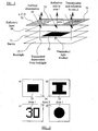
- LCD 22 An example of the LCD 22 is illustrated diagrammatically in Figure 4 and may be of the type illustrated in Figure 2 having a microreflective structure in the form of a reflective layer 30.
- the rear parallax barrier is shown at 31 and the backlight is shown at 13.
- the parallax barrier 31 comprises transparent elongate slits which are arranged parallel to each other and evenly spaced. However, the barrier 31 has a region 32 forming an opaque screen which blocks the transmission of light from the backlight 13 through a first region 33 ("area one") of the LCD 22. The first region 33 is surrounded by a second region 34 ("area two") which is not screened from light from the backlight 13. Thus, ambient illumination 35 from the front of the LCD 22 is reflected by the reflective layer 30 through both the first region 33 and the second region 34 whereas transmitted illumination from the backlight 13 passes through the second region 34 but is blocked by the screen 32 and does not pass through the first region 33.
- the backlight has a first portion behind the first region 33 which can be switched off independently of a second portion of the backlight behind the second region 34.
- the opaque screen 32 is thus not necessary and may be omitted.
- the pixels of the LCD 22 in the first region 33 are set by the controller 23 to maximum transmissivity.
- the pixels of one colour such as red are set to maximum intensity whereas the green and blue pixels are set to minimum intensity or transmissivity.
- the green and blue pixels in the second region 34 are set by the controller 23 to minimum transmissivity whereas the red pixels in the second region 34 are set by the controller 23 to a fraction A of maximum transmissivity.
- the intensity of ambient light reflected through the first region 33 is represented by R whereas the total reflected and transmitted intensity from the second region 34 is given by (T+R)A, where T represents the transmitted intensity through the region 34.
- R A ⁇ T + R
- A represents the fractional intensity or transmissivity for the second region 34 such that the first and second regions appear to have the same intensity when the reflected light is equal to a certain proportion of the transmitted light (R/T).
- the level of crosstalk added by the reflected light is also given by A.
- Figure 5 illustrates four examples of appearances of the first and second regions. An observer has to assess whether the amount of reflected ambient light is problematic so that these regions are arranged to provide a clear indication.
- the shapes illustrated at (a), (b) and (d) are in the form of "icons” and do not in themselves have any particular meaning. However, they do permit a clear assessment of the prevailing conditions to be made by the observer.
- the shape illustrated at (c) is in the form of text characters "3D" and indicates that the display is in the 3D operating mode.
- the shape may be in the form of a number, which may, for example, represent the value of the fractional intensity A and hence the value of crosstalk which would be present in the transmissive autostereoscopic 3D mode of operation.
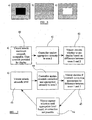
- Figure 6 illustrates diagrammatically how the regions would appear depending on the amount of ambient light being reflected from the display.
- the icon shown at Figure 5 (a) is illustrated for three different conditions of ambient lighting.
- area one appears darker than area two to the observer. If the fractional intensity A has been set to represent the maximum amount of crosstalk which can be accepted during autostereoscopic viewing, then this appearance would signify to the observer that the display can continue to be used in the autostereoscopic 3D mode.
- Figure 6 (b) illustrates the condition in which first and second regions have the same appearance i.e. have the same lighting intensity. When the first and second regions appear like this to the observer, the amount of reflected ambient light is at the limit for autostereoscopic viewing of the display.
- Figure 6 (c) illustrates the condition in which the first region appears brighter than the second region and this corresponds to a relatively large amount of reflected ambient light. This appearance indicates that the amount of crosstalk caused by the reflected ambient illumination is unacceptably high and the display should not therefore be used in the autostereoscopic mode.
- the display may merely provide indications to an observer as to the present viewing conditions with regard to the level of reflected ambient light and the level of crosstalk which would occur during autostereoscopic use. It may then be left to the observer to decide whether to stop using the display or switch the display to a non-autostereoscopic mode, such as a transmissive or reflective 2D mode of operation. For example, as a result of observing the appearance of the first and second regions, the observer may use the mouse 24 or 26 to interact with the graphical user interface so as to change the mode of operation.
- a manually operable button may be provided for changing between display modes and this may carry or be adjacent a label having the same appearance as the first region so as to guide a user towards operating the button when the operating mode should be changed.
- the label may have the same pattern as the first and second regions.
- the indicator region may have the pattern shown in Figure 5(c) and the label would then have the same pattern.
- the label would also have the same colours as the indicator area either when the indicator shows a good state or when the indicator shows a bad state.
- the observer may have further interaction with the display as described hereinafter.
- Figure 7 illustrates two ways in which the display may be operated according to the ambient lighting conditions.
- a "passive" interaction is illustrated whereby, at 40, the observer or viewer selects the maximum crosstalk which is acceptable for autostereoscopic viewing.
- the observer uses controls provided by the graphical user interface of the display, perhaps also using a keyboard (not shown), to set the maximum value of crosstalk as a percentage.
- the controller 23 then applies the appropriate intensity value A to the pixels of the second region 34 as shown at 41 and, as shown at 42, the observer decides whether to use the display in the autostereoscopic mode in accordance with the appearances of the first and second regions, as described hereinbefore.
- the step 40 may be varied, for example such that the controller 23 determines the value of T/R on the basis of a choice made by the manufacturer. Alternatively, the step 40 may be performed such that the observer cycles through different selections and indicates a choice to the controller 23, for example using the mouse 24.
- a further possibility is that there is a plurality of first and second regions arranged to appear at different positions on the display, for example configured as different icons or as different numbers representing possible selections of maximum crosstalk values.
- the observer judges which "indicator” is such that the first and second regions have the same or closest brightnesses and may use the mouse 24 or 26 to point to and select the appropriate icon or crosstalk value if further interaction with the display is then possible.
- the second region 34 may be arranged in the form of a scale representing a range of crosstalk values which appears as discrete values or substantially continuous values. The observer can judge which part of the scale is closest in brightness to an adjacent part of the first region and either make a decision shown at 42 or use the mouse to indicate the current value of crosstalk to the display.
- Figure 7 (b) illustrates an alternative technique in which crosstalk correction is applied provided the level of crosstalk indicated to the display is less than a maximum threshold value.
- the observer indicates to the display by means of the mouse 24 or 26 or by any other manually operable control the current level of crosstalk caused by the prevailing ambient illumination.
- the controller 23 applies crosstalk correction by processing the image data supplied from the computer 21, for example in accordance with the crosstalk correction technique disclosed in EP 0 953 962 .
- the controller applies the appropriate intensity A to the second region 34 corresponding to the selected crosstalk level.
- the observer decides from the appearance of the first and second regions whether the crosstalk correction provided by the controller 23 is appropriate for the prevailing conditions. If the correction is not appropriate, the selection of the crosstalk level is repeated at 46 and a reassessment made until the appropriate crosstalk correction is achieved or it is found that correction cannot be achieved, for example because the crosstalk is excessive.
- the upper limit on the amount of correction which may be applied may be dependent on the image or may be set in the design of the display, for example depending on the crosstalk correction technique actually used.
- the parameter A may be set to a value smaller than the maximum ambient brightness level and, instead of setting the pixels in the first region 33 to full brightness, they may be set to a brightness or transmissivity in accordance with an attenuating factor or parameter B.
- the parameter B may then be adjusted until the first and second regions appear to match in brightness to the observer.
- the crosstalk value is then given by the value of A/B.
- the "brightness" indicator formed by the first and second regions may be located within the area of a display providing a visual position indicator of the type disclosed in EP 0 860 728 .
- a visual position indicator is used by an observer to indicate whether he or she is at a correct position with respect to the display in order to have autostereoscopic viewing of the images displayed by the display.
- the visual position indicator occupies a region which is visible to the observer and provides an indication which, when the observer is correctly positioned, is effectively invisible to the observer. The indication only becomes visible when the observer is in an incorrect viewing position, for example giving rise to pseudoscopic viewing.
- Such an indicator does not therefore direct light to the normal viewing position for autostereoscopic viewing but may be used to provide brightness indication.
- the area two pixels may be those located at the edges of the screen whereas the area one pixels may be those located everywhere accept at the edge of the screen.
- some of the slits of the barrier 31 forming the visual position indicator may be "removed" so as to be opaque and prevent transmission of light from the backlight 13 in order to provide a larger number of pixels to form the area one.
- the first and second regions 33 and 34 are provided as spatially separate regions on the LCD 22. In an alternative set of embodiments, these regions may be defined temporally. In such embodiments, the screen 32 is unnecessary and is not therefore present. Instead, the controller 23 is arranged to switch the LCD 22, at least during a crosstalk-assessing mode, between two phases of operation. In the first phase, all of the pixels are lit at full brightness and the backlight 13 is switched off. In the second phase, all of the pixels are set to a brightness specified by the parameter A and the backlight 13 is switched on. Switching between states may be performed manually or automatically by the controller 23.
- more limited regions may be used to provide the crosstalk indication, for example to allow the observer to assess the actual amount of crosstalk and to signal this to the display so that, for example, automatic crosstalk correction may be provided as described hereinbefore or the display may automatically switch from the autostereoscopic mode to, for example, the 2D mode.
Landscapes
- Engineering & Computer Science (AREA)
- Multimedia (AREA)
- Signal Processing (AREA)
- Physics & Mathematics (AREA)
- Nonlinear Science (AREA)
- Crystallography & Structural Chemistry (AREA)
- Chemical & Material Sciences (AREA)
- Mathematical Physics (AREA)
- General Physics & Mathematics (AREA)
- Optics & Photonics (AREA)
- Control Of Indicators Other Than Cathode Ray Tubes (AREA)
- Testing, Inspecting, Measuring Of Stereoscopic Televisions And Televisions (AREA)
- Liquid Crystal (AREA)
Claims (22)
- Autostereoskopische Anzeige,
mit einem pixelartigen transflektiven räumlichen Lichtmodulator (22), einer Hintergrundbeleuchtung (13) und einem Parallaxenelement (31), das zwischen dem Modulator (22) und der Hintergrundbeleuchtung (13) angeordnet ist,
gekennzeichnet durch aufweisend:eine Anordnung (32) zum im Wesentlichen Verhindern einer Transmission von Licht von der Hintergrundbeleuchtung durch mindestens ein erstes Gebiet (33) des Modulators (22) zu einem autostereoskopischen Sichtbereich der Anzeige, während eine Reflexion von Umgebungslicht durch den Modulator erlaubt wird, undeine Steuerung (23) zum Einstellen mindestens einiger der Pixel des mindestens einen ersten Gebiets (33) auf eine erste Durchlässigkeit und zum simultanen Einstellen mindestens einiger der Pixel mindestens eines zweiten Gebiets (34) des Modulators auf eine zweite vorbestimmte Durchlässigkeit, die geringer ist als die erste Durchlässigkeit, um ein Bild anzuzeigen, um einem Benutzer eine Angabe für das Niveau reflektierten Umgebungslichts zu liefern, wobei die Angabe auf einem visuellen Vergleich zwischen der Helligkeit des mindestens einen ersten Gebiets (33) und der Helligkeit des mindestens einen zweiten Gebiets (34) basiert. - Anzeige nach Anspruch 1,
dadurch gekennzeichnet,
dass die Anordnung einen Schirm (32) aufweist zum im Wesentlichen Verhindern der Transmission von Licht der Hintergrundbeleuchtung (13) durch das mindestens eine erste Gebiet (33). - Anzeige nach Anspruch 1,
dadurch gekennzeichnet,
dass die Anordnung einen ersten Bereich der Hintergrundbeleuchtung (13) aufweist, der hinter dem mindestens einen ersten Gebiet (33) angeordnet ist, und welcher unabhängig von einem zweiten Bereich der Hintergrundbeleuchtung (13) ausschaltbar ist, welcher hinter dem mindestens einen zweiten Gebiet (34) angeordnet ist. - Autostereoskopische Anzeige mit einem pixelartigen transflektiven räumlichen Lichtmodulator (22), einer Hintergrundbeleuchtung (13) und einem Parallaxenelement (31), welches zwischen dem Modulator (22) und der Hintergrundbeleuchtung (13) angeordnet ist,
gekennzeichnet durch AU AUF
aufweisend eine Steuerung (23) zum alternierenden Auswählen erster und zweiter Phasen eines Betriebs, um einem Benutzer einer visuelle Angabe des Niveaus reflektierten Umgebungslichts zu liefern,
wobei während der ersten Phase die Steuerung (23) mindestens einige der Pixel mindestens eines ersten Gebiets des Modulators (22) auf eine erste Durchlässigkeit einstellt und die Hintergrundbeleuchtung (13) einstellt, um Licht einer ersten Intensität durch mindestens einige der mindestens einigen Pixel des mindestens einen ersten Gebiets bereitzustellen, und
wobei während der zweiten Phase die Steuerung (23) mindestens einige der Pixel mindestens eines zweiten Gebiets des Modulators (22) auf eine zweite Durchlässigkeit, die geringer ist als die erste Durchlässigkeit, einstellt und die Hintergrundbeleuchtung (13) einstellt, um Licht einer zweiten Intensität, die größer ist als die erste Intensität, durch mindestens einige der mindestens einigen Pixel des mindestens einen zweiten Gebiets bereitzustellen, und
wobei die Angabe auf einem visuellen Vergleich zwischen der Helligkeit des mindestens einen ersten Gebiets (33) und der Helligkeit des mindestens einen zweiten Gebiets (34) basiert. - Anzeige nach Anspruch 4,
dadurch gekennzeichnet,
dass das mindestens eine erste Gebiet mindestens teilweise das mindestens eine zweite Gebiet überlappt. - Anzeige nach Anspruch 5,
dadurch gekennzeichnet,
dass das mindestens eine erste Gebiet und das mindestens eine zweite Gebiet jeweils die gesamte Anzeigefläche des Modulators (22) umfassen. - Anzeige nach einem der Ansprüche 4 bis 6,
dadurch gekennzeichnet,
dass die Steuerung (23) ausgebildet ist, automatisch zwischen den ersten und zweiten Phasen zu schalten. - Anzeige nach einem der Ansprüche 4 bis 6,
gekennzeichnet durch aufweisend eine erste manuell betätigbare Steuerung (24) zum Schalten zwischen den ersten und zweiten Phasen. - Anzeige nach einem der vorangehenden Ansprüche
dadurch gekennzeichnet,
dass das Parallaxenelement eine Parallaxenbarriere (31) aufweist. - Anzeige nach Anspruch 2 oder nach Anspruch 9, soweit dieser von Anspruch 2 abhängig ist,
dadurch gekennzeichnet,
dass der Schirm (32) einen Teil des Parallaxenelements (31) aufweist. - Anzeige nach einem der vorangehenden Ansprüche,
dadurch gekennzeichnet,
dass die erste Durchlässigkeit zum Maximum der Durchlässigkeit der Pixel gleich ist. - Anzeige nach einem der vorangehenden Ansprüche,
dadurch gekennzeichnet,
dass das mindestens eine zweite Gebiet (34) eine Mehrzahl zweiter Gebiete aufweist. - Anzeige nach Anspruch 12,
dadurch gekennzeichnet,
dass die Steuerung (23) ausgebildet ist, die Pixel der unterschiedlichen zweiten Gebiete auf unterschiedliche zweite Durchlässigkeiten einzustellen. - Anzeige nach einem der Ansprüche 1 bis 11,
dadurch gekennzeichnet,
dass die Steuerung (23) ausgebildet ist, die Pixel des mindestens einen zweiten Gebiets (34) auf irgendeine einer Mehrzahl zweiter Durchlässigkeiten einzustellen. - Anzeige nach Anspruch 13 oder 14,
dadurch gekennzeichnet,
dass die Pixel für jede zweite Durchlässigkeit eine Anordnung bilden, die eine visuelle Darstellung eines Übersprech- oder Einstreuwerts korrespondierend zur zweiten Durchlässigkeit schafft. - Anzeige nach einem der Ansprüche 13 bis 15,
gekennzeichnet durch aufweisend eine zweite manuell betätigbare Steuerung (24) zum Auswählen irgendeiner der zweiten Durchlässigkeiten. - Anzeige nach Anspruch 16,
dadurch gekennzeichnet,
dass die Steuerung (23) ausgebildet ist, einen oder den Übersprech- oder Einstreuwert korrespondierend zur zweiten ausgewählten Durchlässigkeit zu schaffen. - Anzeige nach Anspruch 17,
dadurch gekennzeichnet,
dass die Steuerung (23) ausgebildet ist, eine Übersprech- oder Einstreukorrektur autostereoskopischer Bilddaten für den Modulator (22) gemäß dem Übersprech- oder Einstreuwert auszuführen. - Anzeige nach einem der vorangehenden Ansprüche,
gekennzeichnet durch aufweisend einen zweidimensionalen Betriebsmodus. - Anzeige nach Anspruch 19, soweit dieser abhängig ist von Anspruch 17 oder 18,
dadurch gekennzeichnet,
dass die Steuerung (23) ausgebildet ist, zum zweidimensionalen Modus zu schalten, wenn der Übersprech- oder Einstreuwert einen vorgegebenen Schwellenwert überschreitet. - Anzeige nach einem der vorangehenden Ansprüche,
dadurch gekennzeichnet,
dass die mindestens einigen Pixel der ersten und zweiten Gebiete (33, 34) von derselben Farbe sind. - Anzeige nach einem der vorangehenden Ansprüche,
dadurch gekennzeichnet,
dass der Modulator (22) eine Flüssigkristalleinrichtung aufweist.
Applications Claiming Priority (2)
| Application Number | Priority Date | Filing Date | Title |
|---|---|---|---|
| GB0216608A GB2390948A (en) | 2002-07-17 | 2002-07-17 | Autostereoscopic display |
| GB0216608 | 2002-07-17 |
Publications (3)
| Publication Number | Publication Date |
|---|---|
| EP1383343A2 EP1383343A2 (de) | 2004-01-21 |
| EP1383343A3 EP1383343A3 (de) | 2005-01-26 |
| EP1383343B1 true EP1383343B1 (de) | 2013-06-12 |
Family
ID=9940645
Family Applications (1)
| Application Number | Title | Priority Date | Filing Date |
|---|---|---|---|
| EP03102051.4A Expired - Lifetime EP1383343B1 (de) | 2002-07-17 | 2003-07-08 | Autostereoskopische Bildanzeigevorrichtung |
Country Status (6)
| Country | Link |
|---|---|
| US (1) | US7505061B2 (de) |
| EP (1) | EP1383343B1 (de) |
| JP (1) | JP2004054273A (de) |
| KR (1) | KR100678551B1 (de) |
| CN (1) | CN1306315C (de) |
| GB (1) | GB2390948A (de) |
Families Citing this family (25)
| Publication number | Priority date | Publication date | Assignee | Title |
|---|---|---|---|---|
| US7371163B1 (en) | 2001-05-10 | 2008-05-13 | Best Robert M | 3D portable game system |
| US7445549B1 (en) | 2001-05-10 | 2008-11-04 | Best Robert M | Networked portable and console game systems |
| US20050210400A1 (en) * | 2004-03-19 | 2005-09-22 | Peter Hoe-Richardson | Controlling display screen legibility |
| US7644369B2 (en) * | 2004-03-19 | 2010-01-05 | Rocket Software, Inc. | Controlling display screen legibility |
| DK2202609T3 (en) * | 2004-06-18 | 2016-04-25 | Tobii Ab | Eye control of computer equipment |
| US7522236B2 (en) * | 2005-09-23 | 2009-04-21 | Apple Inc. | Cosmetically uniform reflective border area in a transflective display |
| KR100704634B1 (ko) | 2005-12-19 | 2007-04-09 | 삼성전자주식회사 | 사용자의 위치에 따른 입체 영상을 디스플레이하는 장치 및방법 |
| CN100374907C (zh) * | 2006-01-27 | 2008-03-12 | 张凯明 | 裸眼可视液晶快门光筛立体图像显示装置及其显示方法 |
| US7986375B2 (en) * | 2006-08-17 | 2011-07-26 | Koninklijke Philips Electronics N.V. | Multi-view autostereoscopic display device having particular driving means and driving method |
| CN101170709B (zh) * | 2006-10-23 | 2010-12-01 | 奇美电子股份有限公司 | 控制显示面板的多数个显示区域的方法及显示器 |
| EP2122409B1 (de) * | 2007-02-25 | 2016-12-07 | Humaneyes Technologies Ltd. | Verfahren und system zum kalibrieren und/oder visualisieren einer mehrbildanzeige und zum verringern von ghosting-artefakten |
| WO2009013744A2 (en) | 2007-07-23 | 2009-01-29 | Humaneyes Technologies Ltd. | Multi view displays and methods for producing the same |
| EP2250820A2 (de) * | 2008-02-08 | 2010-11-17 | Koninklijke Philips Electronics N.V. | Autostereoskopische Anzeigevorrichtung |
| CN101895775B (zh) * | 2009-05-21 | 2012-08-22 | 华映视讯(吴江)有限公司 | 影像处理方法 |
| US7978407B1 (en) | 2009-06-27 | 2011-07-12 | Holovisions LLC | Holovision (TM) 3D imaging with rotating light-emitting members |
| JP5296225B2 (ja) * | 2010-01-13 | 2013-09-25 | 株式会社東芝 | 立体映像表示装置 |
| JP5607430B2 (ja) * | 2010-06-10 | 2014-10-15 | 株式会社ジャパンディスプレイ | 立体映像表示装置及び電子機器 |
| KR101670927B1 (ko) * | 2010-11-05 | 2016-11-01 | 삼성전자주식회사 | 디스플레이 장치 및 방법 |
| US9148645B2 (en) | 2011-05-14 | 2015-09-29 | Dolby Laboratories Licensing Corporation | Crosstalk cancellation in 3D displays |
| KR101887058B1 (ko) * | 2011-11-11 | 2018-08-09 | 엘지전자 주식회사 | 입체영상 처리 장치 및 입체영상 처리 장치의 전력 제어 방법 |
| KR101929561B1 (ko) | 2012-03-20 | 2018-12-18 | 삼성전자주식회사 | 시야각 조절이 가능한 디스플레이 장치 |
| JP6202856B2 (ja) * | 2012-06-21 | 2017-09-27 | キヤノン株式会社 | 画像処理装置、画像処理方法およびプログラム |
| CN104077995B (zh) | 2014-06-30 | 2017-01-04 | 上海天马微电子有限公司 | Tft阵列基板、显示面板及显示装置 |
| KR102409393B1 (ko) | 2017-08-14 | 2022-06-15 | 삼성전자주식회사 | 도광판, 백라이트 유닛 및 이를 포함한 홀로그래픽 디스플레이 장치 |
| CN108540791B (zh) * | 2018-04-25 | 2020-01-24 | 京东方科技集团股份有限公司 | 一种双视显示方法和装置 |
Family Cites Families (10)
| Publication number | Priority date | Publication date | Assignee | Title |
|---|---|---|---|---|
| JPH06110374A (ja) * | 1992-09-30 | 1994-04-22 | Fujitsu Ltd | 立体表示装置 |
| WO1994012913A1 (en) * | 1992-11-27 | 1994-06-09 | Voxel | Methods and apparatus for making holograms |
| US5917562A (en) * | 1994-12-16 | 1999-06-29 | Sharp Kabushiki Kaisha | Autostereoscopic display and spatial light modulator |
| JP3459721B2 (ja) * | 1995-05-22 | 2003-10-27 | キヤノン株式会社 | 立体画像表示方法及びそれを用いた立体画像表示装置 |
| GB2314167B (en) * | 1996-06-13 | 2000-12-20 | Sharp Kk | Liquid crystal device and display arrangement incorporating same |
| JP3244630B2 (ja) * | 1996-08-28 | 2002-01-07 | アルプス電気株式会社 | 液晶表示装置の駆動回路 |
| EP0829744B1 (de) * | 1996-09-12 | 2005-03-23 | Sharp Kabushiki Kaisha | Parallaxeschranke und Anzeigevorrichtung |
| GB2317710A (en) * | 1996-09-27 | 1998-04-01 | Sharp Kk | Spatial light modulator and directional display |
| GB9623682D0 (en) * | 1996-11-14 | 1997-01-08 | Philips Electronics Nv | Autostereoscopic display apparatus |
| JP4196505B2 (ja) | 1999-12-13 | 2008-12-17 | ソニー株式会社 | 表示装置及びその製造方法とカラーフィルタ |
-
2002
- 2002-07-17 GB GB0216608A patent/GB2390948A/en not_active Withdrawn
-
2003
- 2003-07-04 JP JP2003192487A patent/JP2004054273A/ja not_active Withdrawn
- 2003-07-08 EP EP03102051.4A patent/EP1383343B1/de not_active Expired - Lifetime
- 2003-07-09 US US10/615,816 patent/US7505061B2/en not_active Expired - Fee Related
- 2003-07-16 KR KR1020030048778A patent/KR100678551B1/ko not_active Expired - Fee Related
- 2003-07-17 CN CNB031787355A patent/CN1306315C/zh not_active Expired - Fee Related
Also Published As
| Publication number | Publication date |
|---|---|
| CN1306315C (zh) | 2007-03-21 |
| EP1383343A3 (de) | 2005-01-26 |
| GB2390948A (en) | 2004-01-21 |
| KR100678551B1 (ko) | 2007-02-05 |
| EP1383343A2 (de) | 2004-01-21 |
| CN1479132A (zh) | 2004-03-03 |
| JP2004054273A (ja) | 2004-02-19 |
| KR20040008097A (ko) | 2004-01-28 |
| GB0216608D0 (en) | 2002-08-28 |
| US7505061B2 (en) | 2009-03-17 |
| US20040012671A1 (en) | 2004-01-22 |
Similar Documents
| Publication | Publication Date | Title |
|---|---|---|
| US7505061B2 (en) | Autostereoscopic display | |
| JP5615136B2 (ja) | 立体画像補正方法、立体表示装置、および立体画像生成装置 | |
| US6970290B1 (en) | Stereoscopic image display device without glasses | |
| JP5576762B2 (ja) | ディスプレイ制御装置 | |
| JP3660610B2 (ja) | 画像表示方法 | |
| KR101073044B1 (ko) | 2차원 서브픽셀 레이아웃을 갖는 디스플레이 패널을 위한 영상 색 균형 처리 방법 | |
| EP1401216A2 (de) | Autostereoskopische Bildanzeigevorrichtung | |
| EP0347790A2 (de) | Flüssigkristallanzeigeeinheit und Methode zur Anzeige eines Bildes mit einer derartigen Einheit | |
| EP0860728A1 (de) | Autostereoskopische Anzeigevorrichtung | |
| JP2001166259A (ja) | 眼鏡無し立体映像表示装置 | |
| GB2428345A (en) | A display having multiple view and single view modes | |
| EP0786911A2 (de) | Räumlicher Lichtmodulator und gerichtete Anzeigevorrichtung | |
| EP2122605A1 (de) | Verfahren und vorrichtung zur verarbeitung von bilddaten zur anzeige auf einem mehransichts-anzeigegerät | |
| RU2005129545A (ru) | Способ и система для создания пространственных изображений | |
| WO2007040413A1 (en) | Method of manipulating visibility of images on a volumetric display | |
| CN101589421A (zh) | 图像处理设备、方法、程序和显示器 | |
| DE102013112621B4 (de) | Stereobild-Anzeigevorrichtung mit Verfahren zum Ansteuern | |
| GB2404106A (en) | Generating a test image for use in assessing display crosstalk. | |
| KR20170002614A (ko) | 디스플레이에 대한 구동 값들의 생성 | |
| EP1683367B1 (de) | Mehrebenen-display zum anzeigen sich überlappender bilder | |
| JP2008299040A (ja) | 画像表示装置 | |
| JP2843087B2 (ja) | 立体画像表示装置 | |
| EP1460857A1 (de) | Verfahren und Vorrichtung zur Geisterbilderkompensation in zeitsequentiellen stereoskopischen Bildern | |
| CN207440472U (zh) | 显示装置及影像显示系统 | |
| JP2005091448A (ja) | 立体画像表示装置 |
Legal Events
| Date | Code | Title | Description |
|---|---|---|---|
| PUAI | Public reference made under article 153(3) epc to a published international application that has entered the european phase |
Free format text: ORIGINAL CODE: 0009012 |
|
| AK | Designated contracting states |
Kind code of ref document: A2 Designated state(s): AT BE BG CH CY CZ DE DK EE ES FI FR GB GR HU IE IT LI LU MC NL PT RO SE SI SK TR |
|
| AX | Request for extension of the european patent |
Extension state: AL LT LV MK |
|
| 17P | Request for examination filed |
Effective date: 20040601 |
|
| PUAL | Search report despatched |
Free format text: ORIGINAL CODE: 0009013 |
|
| AK | Designated contracting states |
Kind code of ref document: A3 Designated state(s): AT BE BG CH CY CZ DE DK EE ES FI FR GB GR HU IE IT LI LU MC NL PT RO SE SI SK TR |
|
| AX | Request for extension of the european patent |
Extension state: AL LT LV MK |
|
| AKX | Designation fees paid |
Designated state(s): DE FR GB |
|
| 17Q | First examination report despatched |
Effective date: 20100219 |
|
| GRAP | Despatch of communication of intention to grant a patent |
Free format text: ORIGINAL CODE: EPIDOSNIGR1 |
|
| RIN1 | Information on inventor provided before grant (corrected) |
Inventor name: MONTGOMERY, DAVID, JAMES Inventor name: MUSGRAVE, BRONJE, MARY Inventor name: BOURHILL, GRANT Inventor name: JACOBS, ADRIAN, MARK, SIMON Inventor name: JONES, GRAHAM |
|
| GRAS | Grant fee paid |
Free format text: ORIGINAL CODE: EPIDOSNIGR3 |
|
| GRAA | (expected) grant |
Free format text: ORIGINAL CODE: 0009210 |
|
| AK | Designated contracting states |
Kind code of ref document: B1 Designated state(s): DE FR GB |
|
| REG | Reference to a national code |
Ref country code: GB Ref legal event code: FG4D |
|
| REG | Reference to a national code |
Ref country code: DE Ref legal event code: R096 Ref document number: 60344259 Country of ref document: DE Effective date: 20130801 |
|
| PLBE | No opposition filed within time limit |
Free format text: ORIGINAL CODE: 0009261 |
|
| STAA | Information on the status of an ep patent application or granted ep patent |
Free format text: STATUS: NO OPPOSITION FILED WITHIN TIME LIMIT |
|
| 26N | No opposition filed |
Effective date: 20140313 |
|
| REG | Reference to a national code |
Ref country code: DE Ref legal event code: R097 Ref document number: 60344259 Country of ref document: DE Effective date: 20140313 |
|
| REG | Reference to a national code |
Ref country code: FR Ref legal event code: PLFP Year of fee payment: 13 |
|
| PGFP | Annual fee paid to national office [announced via postgrant information from national office to epo] |
Ref country code: FR Payment date: 20150626 Year of fee payment: 13 |
|
| PGFP | Annual fee paid to national office [announced via postgrant information from national office to epo] |
Ref country code: DE Payment date: 20150721 Year of fee payment: 13 Ref country code: GB Payment date: 20150721 Year of fee payment: 13 |
|
| REG | Reference to a national code |
Ref country code: DE Ref legal event code: R119 Ref document number: 60344259 Country of ref document: DE |
|
| GBPC | Gb: european patent ceased through non-payment of renewal fee |
Effective date: 20160708 |
|
| PG25 | Lapsed in a contracting state [announced via postgrant information from national office to epo] |
Ref country code: FR Free format text: LAPSE BECAUSE OF NON-PAYMENT OF DUE FEES Effective date: 20160801 Ref country code: DE Free format text: LAPSE BECAUSE OF NON-PAYMENT OF DUE FEES Effective date: 20170201 |
|
| REG | Reference to a national code |
Ref country code: FR Ref legal event code: ST Effective date: 20170331 |
|
| PG25 | Lapsed in a contracting state [announced via postgrant information from national office to epo] |
Ref country code: GB Free format text: LAPSE BECAUSE OF NON-PAYMENT OF DUE FEES Effective date: 20160708 |